Moxa Technologies AWK-4121 Quick Installation Manual
Hide thumbs
Also See for AWK-4121:
- User manual (89 pages) ,
- Quick installation manual (15 pages) ,
- Installation manual (14 pages)
Table of Contents
Advertisement
Quick Links
Quick Installation Guide
Moxa Americas:
Toll-free: 1-888-669-2872
Tel:
1-714-528-6777
Fax:
1-714-528-6778
Moxa Europe:
Tel:
+49-89-3 70 03 99-0
Fax:
+49-89-3 70 03 99-99
Moxa India:
Tel:
+91-80-4172-9088
Fax:
+91-80-4132-1045
AWK-4121
Moxa AirWorks
Edition 6.0, June 2016
Technical Support Contact Information
www.moxa.com/support
2016 Moxa Inc. All rights reserved.
Moxa China (Shanghai office):
Toll-free: 800-820-5036
Tel:
+86-21-5258-9955
Fax:
+86-21-5258-5505
Moxa Asia-Pacific:
Tel:
+886-2-8919-1230
Fax:
+886-2-8919-1231
P/N: 1802041210015
*1802041210015*
Advertisement
Table of Contents

Subscribe to Our Youtube Channel
Related Manuals for Moxa Technologies AWK-4121


Summary of Contents for Moxa Technologies AWK-4121
-
Page 1: Quick Installation Guide
AWK-4121 Quick Installation Guide Moxa AirWorks Edition 6.0, June 2016 Technical Support Contact Information www.moxa.com/support Moxa Americas: Moxa China (Shanghai office): Toll-free: 1-888-669-2872 Toll-free: 800-820-5036 Tel: 1-714-528-6777 Tel: +86-21-5258-9955 Fax: 1-714-528-6778 Fax: +86-21-5258-5505 Moxa Europe: Moxa Asia-Pacific: Tel: +49-89-3 70 03 99-0... -
Page 2: Package Checklist
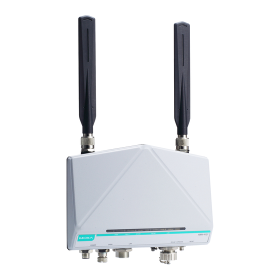
DC power inputs for increased reliability, can be powered via PoE (discontinued starting with HW Rev 2.0.0), and is easy to deploy. Package Checklist Moxa’s AWK-4121 is shipped with the following items. If any of these items is missing or damaged, please contact your customer service representative for assistance. - Page 3 Panel Layout of the AWK-4121 1. MAIN antenna port. 2. AUX antenna port. 3. LEDs for PWR, FAULT, STATE, WLAN and LAN. 4. M12 A-coding connector for PWR1 and PWR2. 5. M12 8-pin connector for DI/DO 6. 10/100BaseT(X) RJ45 Port 7.
-
Page 4: Dimensions (Unit = Mm)
Rubber plate Antenna Metal N-type Step 1: Use your fingers and hold the antenna metal N-type connector. Step 2: Screw the antenna N-type connector (male) onto the AWK-4121 device’s N-type connector (female) Caution Do not hold the rubber plate to screw the antenna on to the AWK-4121 device. -
Page 5: Wall Mounting
Wall Mounting In most applications, wall mount provides an easier installation. You will find it quite easy to mount AWK-4121 on the wall, as illustrated below. STEP 1: STEP 2: Attach the wall-mounting kit Mounting the AWK-4121 on the wall with M4 screws, as shown in requires 4 screws. -
Page 6: Din-Rail Mounting (Optional)
AWK-4121. A pair of DK-DC50131s is needed for DIN-rail mounting. To install the DIN-rail mounting kits, tightly attach the two DIN-rail mounting kits on the rear panel of AWK-4121 with 12 screws. (6 screws for each kit) To Install STEP 1:... -
Page 7: Wiring Requirements
WARNING Safety First! Be sure to disconnect the power cord before installing and/or wiring your Moxa AWK-4121. Calculate the maximum possible current in each power wire and common wire. Observe all electrical codes dictating the maximum current allowable for each wire size. If the current goes above the maximum ratings, the wiring could overheat, causing serious damage to your equipment. - Page 8 stable power input for the AWK. Installations with Cable Extended Antennas for Outdoor Applications If the antenna or the AWK device is installed outdoors or in an open-air setting, proper lightning protection is required to prevent direct lightning strikes on the AWK device. In order to prevent coupling currents from nearby lightning strikes, a lightning arrester should be installed as part of your antenna system.
-
Page 9: Wiring The Redundant Power Inputs
Wiring the Digital Inputs and Relay Contact (Digital Output) The AWK-4121 has two sets of digital input—DI1 and DI2. Each DI comprises two contacts of the 8-pin M12 connector on the AWK-4121’s bottom panel. These two digital inputs can be connected to digital-output-enabled sensors for on-site status monitoring. -
Page 10: Communication Connections
Signal Signal RS-232 Connection The AWK-4121 has one RS-232 (8-pin RJ45) console port located on the bottom panel. Use either an RJ45-to-DB9 or RJ45-to-DB25 cable to connect the Moxa AWK-4121’s console port to your PC’s COM port. You may then use a console terminal program to access the AWK-4121 for console configuration. -
Page 11: Waterproof Rj45 Plug
ATTENTION To ensure the IP68-rated connectivity, you must use a waterproof housing during any communication activities. An IP68-rated field installable plug, which is attached in AWK-4121’s accessory pack, may be needed in this case. The installation guide is shown below:... -
Page 12: Led Indicators
(NOTE: for a tighter connection, you can connect the RJ-45 plug to the AWK-4121 before STEP 4.) LED Indicators The front panel of the Moxa AWK-4121 contains several LED indicators. The function of each LED is described in the table below. Color State... -
Page 13: Specifications
Blinking (slow at Device has been located by Wireless 1-second Utility intervals) System is booting up WLAN function is in Client/Slave mode. WLAN’s data communication is run in Green Blinking Client/Slave mode WLAN is not in use or not working WLAN properly WLAN function is in AP/Bridge mode. - Page 14 • 5.18 to 5.24 GHz (4 channels) • 2.412 to 2.472 GHz (13 channels) • 5.18 to 5.24 GHz (4 channels) • 2.412 to 2.484 GHz (14 channels, channel 14 only supports DSSS) • 5.18 to 5.24 GHz (4 channels for W52) Security SSID broadcast enable/disable Firewall for MAC/IP/Protocol/Port-based filtering...
- Page 15 2.4 GHz, 2 dBi at 5 GHz, N-type (male) Connector for External N-type (female) Antennas RJ45 Ports 1, 10/100BaseT(X), auto negotiation speed Console Port RS-232 (waterproof RJ45-type) Reset Present LED Indicators PWR, FAULT, STATE, WLAN, LAN Alarm Contact 1 relay output with current carrying capacity of 1 A @ 24 VDC, M12 male type Digital Inputs 2 electrically isolated inputs , M12 male type...
- Page 16 ATTENTION The AWK-4121 is NOT a portable mobile device and should be located 20cm away from the human body. The AWK-4121 is NOT designed for the general public. To deploy AWK-4121s and establish a wireless network safely, a well-trained technician is required for installation.
- Page 17 - 17 -...
Need help?
Do you have a question about the AWK-4121 and is the answer not in the manual?
Questions and answers