
Related Manuals for Rosemount SOLU COMP II


Summary of Contents for Rosemount SOLU COMP II
- Page 1 Instruction Manual ® PN 5101055pH Model SOLU COMP July 2000 Dual Input pH Analyzer Model Options 1055-22-32 and 1055-22...
- Page 2 ESSENTIAL INSTRUCTIONS WARNINGS RISK OF ELECTRICAL SHOCK READ THIS PAGE BEFORE PROCEEDING! Your purchase from Rosemount Analytical, Inc. has Equipment protected throughout by double insulation. resulted in one of the finest instruments available for your particular application. These instruments have •...
- Page 3 2. Wire pH (or ORP) sensor(s) to the analyzer. See the drawings below. Refer to the sensor instruction sheet for details. Make alarm, output, and power connections as shown below. Wiring Connections for Solu Comp II Model 1055-01-10 Wiring Connections for Solu Comp II Model 1055-02-10...
- Page 4 4. When the analyzer is powered up for the first time, Quick Start screens appear. Using Quick Start is easy. a. A blinking field shows the position of the cursor. b. Use the # or $ key to move the cursor left or right. Use the " or ' key to increase or decrease the value of a digit.
- Page 5 QUICK REFERENCE GUIDE MENU TREE FOR pH/ORP/REDOX MEASUREMENTS...
-
Page 6: Table Of Contents
D D I I S S P P L L A A Y Y A A N N D D O O P P E E R R A A T T I I O O N N ..................................Display ........................Keypad ........................Programming and Calibrating the Solu Comp II - Tutorial ........Security ........................Using Hold ....................... - Page 7 Three-Wire RTD Inputs ..................... Simulating RTD Inputs....................Checking for a Poisoned Reference Electrode ............LIST OF TABLES Number Title Page Default Settings ......................Replacement Parts for Solu Comp II (Panel Mount Version)........Replacement Parts for Solu Comp II (Pipe/Surface Mount Version) ......
-
Page 8: Features And Applications
QUICK START PROGRAMMING: Exclusive Quick the push of a button. Start screens appear the first time the Solu Comp II is powered up. Screen prompts direct the user to regis- ter the number of sensors, the measurement unit(s), TEMPERATURE CORRECTION: and language. -
Page 9: Specifications
MODEL SOLU COMP II SECTION 1.0 DESCRIPTION AND SPECIFICATIONS 1.2 SPECIFICATIONS - General Alarms: Three alarm relays for process measure- ment(s) or temperature. Alarm 3 can be Case: ABS. Pipe, surface, and panel mount versions configured as a fault alarm, instead of a are NEMA 4X/CSA 4. -
Page 10: Recommended Sensors
Model 370 and 371 EuroSenz pH Model 404 Flow-Through Model 381+ Insertion/Submersion/Flow Through pH Model 389 Disposable pH The analyzer can also be used with other Rosemount Model 396 Disposable pH Analytical conductivity sensors having titanium elec- Model 396VP Disposable pH with VP 6.0 connector trodes and a Pt 1000 RTD. -
Page 11: Ordering Information And Accessories
DESCRIPTION AND SPECIFICATIONS 1.4 ORDERING INFORMATION The Solu Comp II analyzers offer the choice of single or dual sensor input with measurement choices of pH/ORP and conductivity/resistivity. The pH measurement option offers field configurable measurement units as pH, ORP, or Redox. The conductivity measurement option has measurement unit choices of conductivity and resistivity. -
Page 12: Unpacking And Inspection
Inspect the shipping container. If it is damaged, contact the shipper immediately for instructions. Save the box. If there is no apparent damage, unpack the container. Be sure all items shown on the packing list are present. If items are missing, notify Rosemount Analytical immediately. 2.2 INSTALLATION 2.2.1 General Information... -
Page 13: Panel Mount Installation
MODEL SOLU COMP II SECTION 2.0 INSTALLATION 2.2.2 Panel Mounting. MILLIMETER INCH DWG. NO. REV. 41055C11 FIGURE 2-1. Panel Mount Installation Access to the wiring terminals is through the rear cover. Four screws hold the cover in place. -
Page 14: Pipe Mount Installation
MODEL SOLU COMP II SECTION 2.0 INSTALLATION 2.2.3 Pipe Mounting. MILLIMETER INCH DWG. NO. REV. 41055C10 FIGURE 2-2. Pipe Mount Installation The front panel is hinged at the bottom. The panel swings down for access to the wiring terminals. -
Page 15: Surface Mount Installation
MODEL SOLU COMP II SECTION 2.0 INSTALLATION 2.2.4 Surface Mounting. MILLIMETER INCH DWG. NO. REV. 41055C12 FIGURE 2-3. Surface Mount Installation The front panel is hinged at the bottom. The panel swings down for access to the wiring terminals. -
Page 16: Preparing Conduit Openings
3.2 POWER, ALARM, OUTPUT, AND SENSOR CONNECTIONS The Solu Comp II is available in two mounting configurations.The positions of the power, alarm, output, and sen- sor terminal blocks are different in each. Refer to the table to find the correct drawing. -
Page 17: (Panel Mount With 115/230 Vac Power)
MODEL SOLU COMP II SECTION 3.0 WIRING FIGURE 3-2. Wiring Connections for Solu Comp II Model 1055-01-10 (Panel Mount with 115/230 Vac Power) FIGURE 3-3. Wiring Connections for Solu Comp II Model 1055-02-10 (Panel Mount with 24 Vdc Power) -
Page 18: (Wall/Pipe Mounting With 115/230 Vac Power)
MODEL SOLU COMP II SECTION 3.0 WIRING FIGURE 3-4. Wiring Connections for Solu Comp II Model 1055-01-11 (Surface/Pipe Mounting with 115/230 Vac Power) FIGURE 3-5. Wiring Connections for Solu Comp II Model 1055-02-11 (Surface/Pipe Mounting with 24 Vdc Power) -
Page 19: Display
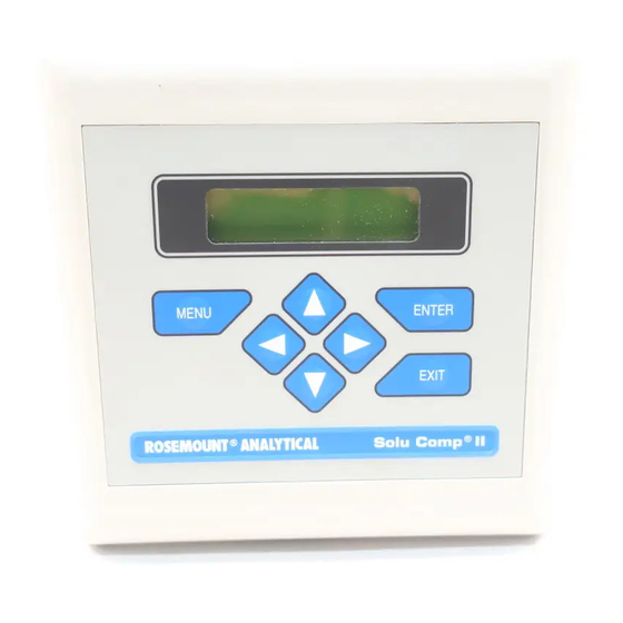
DISPLAY AND OPERATION SECTION 4.0 DISPLAY AND OPERATION 4.1 DISPLAY 4.2 KEYPAD 4.3 PROGRAMMING AND CALIBRATING THE SOLU COMP II - TUTORIAL 4.4 SECURITY 4.5 USING HOLD 4.1. DISPLAY The Solu Comp II has a two-line display. The display can be customized to meet user requirements (see Section 5.11). -
Page 20: Programming And Calibrating The Solu Comp Ii - Tutorial
Press ENTER. Output Range? 6. The screen shown at left appears. The Solu Comp II has two outputs, out- put 1 and output 2. Move the cursor to the desired output and press O O u u t t p p u u t t 1 1 Output2 ENTER. -
Page 21: Security
MODEL SOLU COMP II SECTION 4.0 DISPLAY AND OPERATION 4.4 SECURITY 4.4.1 How the Security Code Works Use the security code to prevent accidental or unwanted changes to program settings, displays, and calibration. Enter Security 1. If a security code has been programmed, pressing MENU causes the security screen to appear. -
Page 22: General
5.2 CHANGING STARTUP SETTINGS When the Solu Comp II is powered up for the first time, startup screens appear. The screens prompt the user to identify the number of sensors being used and whether pH, ORP, or redox is being measured. If incorrect settings were entered at startup, enter the correct settings now. -
Page 23: Default Settings
MODEL SOLU COMP II SECTION 5.0 PROGRAMMING THE ANALYZER TABLE 5-1. DEFAULT SETTINGS 1. SENSOR-OUTPUT ASSIGNMENTS (pH, ORP, or redox is selected during Quick Start) Sensor(s) Output 1 Output 2 Section Single sensor pH/ORP/Redox Temperature 5.3 and 5.9 Dual sensor... -
Page 24: Configuring And Ranging The Outputs
5.3 CONFIGURING AND RANGING THE OUTPUTS. 5.3.1 Purpose The Solu Comp II accepts inputs from two pH or ORP sensors and has two current outputs. This section describes how to configure and range the outputs. CONFIGURE THE OUTPUTS FIRST. 1. Configuring an output means a. - Page 25 MODEL SOLU COMP II SECTION 5.0 PROGRAMMING THE ANALYZER 5.3.3. Procedure: Configure Outputs. To choose a menu item, move the cursor to the item and press ENTER. To store a number or setting, press ENTER. Calibrate Hold 1. Press MENU. The main menu screen appears. Choose Program.
-
Page 26: Configuring Alarms And Assigning Setpoints
2. FAULT ALARM. A fault condition exists when the Solu Comp II detects a problem with a sensor or with the ana- lyzer that is likely to cause seriously erroneous readings. If Alarm 3 was programmed as a fault alarm, the alarm 3 relay will activate. - Page 27 MODEL SOLU COMP II SECTION 5.0 PROGRAMMING THE ANALYZER 5.4.3 Procedure: Configuring Alarms To choose a menu item, move the cursor to the item and press ENTER. To store a number or setting, press ENTER. Calibrate Hold 1. Press MENU. The main menu screen appears. Choose Program.
- Page 28 MODEL SOLU COMP II SECTION 5.0 PROGRAMMING THE ANALYZER 5.4.4 Procedure: Programming Alarm Setpoints To choose a menu item, move the cursor to the item and press ENTER. To store a number or setting, press ENTER. Calibrate Hold 1. Press MENU. The main menu screen appears. Choose Program.
-
Page 29: Selecting Type Of Measurement And Activating Solution Temperature Correction
Most pH cells have isopoten- tial pH reasonably close to 7.00, so the Solu Comp II assumes the cell isopotential pH is 7.00. However, cer- tain specialized electrodes have isopotential pH different from 7.00. - Page 30 MODEL SOLU COMP II SECTION 5.0 PROGRAMMING THE ANALYZER 5.5.3 Procedure. To choose a menu item, move the cursor to the item and press ENTER. To store a number or setting, press ENTER. Calibrate Hold 1. Press MENU. The main menu screen appears. Choose Program.
-
Page 31: Choosing Temperature Units And Manual/Automatic Temperature Compensation
MODEL SOLU COMP II SECTION 5.0 PROGRAMMING THE ANALYZER 5.6 CHOOSING TEMPERATURE UNITS AND MANUAL OR AUTOMATIC TEMPERATURE COMPENSATION 5.6.1 Purpose This section describes how to do the following: 1. Choose temperature display units (°C or °F). 2. Choose automatic or manual temperature compensation. -
Page 32: Setting A Security Code
MODEL SOLU COMP II SECTION 5.0 PROGRAMMING THE ANALYZER 5.7 SETTING A SECURITY CODE 5.7.1 Purpose. This section describes how to set a security code. The security code prevents program and calibration settings from accidentally being changed. Refer to Section 4.4 for additional information. -
Page 33: Single Sensor Or Dual Sensor Input
5.9 SINGLE SENSOR OR DUAL SENSOR INPUT 5.9.1 Purpose The Solu Comp II accepts input from a single sensor or from two sensors. This section describes how to program the analyzer for single or dual sensors. COMPLETE THIS SECTION BEFORE DOING OTHER PROGRAMMING. -
Page 34: Selecting A Default Screen, Language, And Screen Contrast
1. set a default display screen The default display screen is the screen shown during normal operation. The Solu Comp II allows the user to choose from a large number of screens. Which screens are available depends on how the analyzer was con- figured. - Page 35 MODEL SOLU COMP II SECTION 5.0 PROGRAMMING THE ANALYZER 5.11.2 Procedure: Changing Screen Contrast Calibrate Hold 1. Press MENU. The main menu screen appears. Choose Display. D D i i s s p p l l a a y y...
-
Page 36: Introduction
Even then, the error is small. For example, at pH 12 and 25°C, a 1°C error produces a pH error less than ±0.02. 2. During auto calibration, the Solu Comp II recognizes the buffer being used and calculates the actual pH of the buffer at the measured temperature. - Page 37 Let the sample continuously overflow an insulated container hold- ing a calibrated thermometer. 4. Change the Solu Comp II display to match the calibrated thermometer using the procedure below. C C a a l l i i b b r r a a t t e e Hold a.
-
Page 38: Two-Point Buffer Calibration (Auto Calibration)
United States. The Solu Comp II also measures noise and drift and does not accept calibration data until readings are sta- ble. Calibration data will be accepted as soon as the pH reading is constant to within 0.02 units for 10 seconds. - Page 39 MODEL SOLU COMP II SECTION 6.0 CALIBRATION C C a a l l i i b b r r a a t t e e Hold a. Press MENU. The main menu screen appears. Choose Calibrate. Program Display Calibrate? b. Choose Sensor 1 or Sensor 2. For a single input configuration, the Sensor1 Sensor2 screen does not appear.
-
Page 40: Two-Point Buffer Calibration (Manaual Calibration)
2. SLOPE AND OFFSET. Once the Solu Comp II successfully completes the calibration, it calculates and dis- plays the calibration slope and offset. The slope is reported as the slope at 25ºC. Figure 6-1 defines the terms. - Page 41 MODEL SOLU COMP II SECTION 6.0 CALIBRATION C C a a l l i i b b r r a a t t e e Hold a. Press MENU. The main menu screen appears. Choose Calibrate. Program Display Calibrate? b. Choose Sensor 1 or Sensor 2. For a single input configuration, the Sensor1 Sensor2 screen does not appear.
-
Page 42: Making The Analyzer Reading Match A Second Instrument (Standardization)
(STANDARDIZATION) 6.5.1 Purpose 1. The pH measured by the Solu Comp II analyzer can be changed to match the reading from a second or ref- eree instrument. The process of making the two readings agree is called standardization. 2. During standardization, the difference between the two pH values is converted to the equivalent voltage. The voltage, called the reference offset, is added to all subsequent measured cell voltages before they are con- verted to pH. -
Page 43: Entering A Known Slope
6.6.1 Purpose If the electrode slope is known from other measurements, it can be entered directly in the Solu Comp II analyzer. The slope must be entered as the slope at 25°C. To calculate the slope at 25°C from the slope at temperature t°C, use the equation: slope at 25°C = (slope at t°C) -
Page 44: Orp Calibration
In contrast, quinhydrone standards contain toxic quinhydrone and have only an eight-hour shelf life. Iron (II) - iron (III) standard is available from Rosemount Analytical as PN R508-16OZ. The ORP of the standard solution measured against a silver-silver chloride reference electrode is 476±20mA at 25°C. The redox potential is -476±20mA at 25°C. -
Page 45: Overview
7.2 REPLACEMENT PARTS 7.1 OVERVIEW The Solu Comp II analyzer needs little routine maintenance. The calibration of the analyzer and sensor should be checked periodically. To recalibrate the analyzer and sensor, see Section 6.0. Clean the analyzer case and front panel by wiping with a clean soft cloth dampened with water ONLY. Do not use solvent, like alcohol, that might cause a buildup of static charge. -
Page 46: Exploded View Of Solu Comp Ii (Panel Mount Version)
Self-tapping screws, #6 x 1.25 in. Note: Size of screws and washers is for information only. Screws and washers cannot be purchased from Rosemount Analytical. Shipping weights are rounded up to the nearest whole lb or 0.5 kg. FIGURE 7-1. Exploded View of Solu Comp II (Panel Mount Version) -
Page 47: Exploded View Of Solu Comp Ii (Pipe/Surface Mount Version)
#6 x 1.75 in. and four O-rings Note: Size of screws and washers is for information only. Screws and washers cannot be purchased from Rosemount Analytical. Shipping weights are rounded up to the nearest whole lb or 0.5 kg. -
Page 48: Overview
8.1 OVERVIEW The Solu Comp II continuously monitors itself and the sensor for faults. When the analyzer detects a fault, the word fault appears in the display alternately with the measurement. If alarm 3 was configured as a fault alarm, the alarm relay will energize. -
Page 49: Troubleshooting When No Error Message Is Showing
8.2.4 RTD Sense Line for Sensor 1 or Sensor 2 is Open. The Solu Comp II measures temperature using a three-wire RTD inside the sensor. See Figure 8-3. The in and return leads connect the RTD to the measuring circuit in the analyzer. A third wire, called the sense line, is con- nected to the return line. - Page 50 During standardization, the millivolt signal from the pH cell is increased or decreased to force it to agree with the pH reading from a referee instrument. A unit change in pH requires an offset of about 59 mV. The Solu Comp II limits the offset to ±1400 mV.
- Page 51 8.3.4 Invalid Input While Manually Entering Slope. If the sensor slope is known from other sources, it can be entered directly into the analyzer. The Solu Comp II will not accept a slope (at 25°C) outside the range 45 to 60 mV/pH. See section 8.3.2 for troubleshooting sensor slope problems.
-
Page 52: Simulating Inputs
MODEL SOLU COMP II SECTION 8.0 TROUBLESHOOTING 3. Connect a jumper wire between the RTD RETURN and RTD SENSE terminals (see wiring diagrams in Section 3.2). Connect a second jumper wire between the REFERENCE IN and SOLUTION GROUND ter- minals. -
Page 53: Simulating Temperature
Preamplifier is in the Sensor. 8.5 SIMULATING TEMPERATURE 8.5.1 General. The Solu Comp II accepts either a Pt100 or a Pt1000 RTD in a three-wire configuration. See Figure 8-3. FIGURE 8-3. Three-Wire RTD Configuration. Although only two wires are required to connect... -
Page 54: Measuring Reference Voltage
The offset is also applied to the simulated resistance. The Solu Comp II is measuring temperature correctly if the difference between measured temperatures equals the difference between the values in the table to with- in ±0.1°C. - Page 55 MODEL SOLU COMP II SECTION 9.0 RETURN OF MATERIAL SECTION 9.0 RETURN OF MATERIAL GENERAL WARRANTY REPAIR NON-WARRANTY REPAIR 9.1 GENERAL. To expedite the repair and return of instruments, proper communication between the customer and the factory is important. Before returning a product for repair, call 1-949-863-1181 for a Return Materials Authorization (RMA) number.
- Page 56 MODEL SOLU COMP II INDEX INDEX ALARMS Alarm setpoints ........................... 19, 21 Configuring alarms........................19-20 Deadband ........................... 19-20 Fault alarms ..........................19-20 BUFFERS Ordering information ........................Table of buffer values ........................CALIBRATION Entering a known slope ......................ORP calibration........................... Standardization ...........................
- Page 57 MODEL SOLU COMP II INDEX INDEX (cont’d) OUTPUTS Assigning sensors and measurements to outputs..............17-18 Assigning values to the low and high current outputs ..............Choosing 0-20 mA or 4-20 mA ....................Choosing normal or logarithmic outputs ..................Dampening..........................17-18 REDOX (DEFINITION) ........................
- Page 58 FOLD ALONG DOTTED LINES...
- Page 59 For Customer Support Mike Stoessl 24 hours a day/365 days a year, President, Rosemount Analytical-Uniloc Division Call 1-800-854-8257 Complete this registration, fold it in thirds so the return address shows, and drop it in any mailbox, or visit our web- site at www.RAuniloc.com and register on-line to double your standard warranty from 1 year to 2 years.
- Page 60 AND IMPLIED WARRANTIES OF MERCHANTABILITY AND FITNESS FOR A PARTICULAR PURPOSE. RETURN OF MATERIAL Material returned for repair, whether in or out of warranty, should be shipped prepaid to: Rosemount Analytical Inc. Uniloc Division 2400 Barranca Parkway Irvine, CA 92606...
- Page 61 CUSTOMER SUPPORT CENTER 1-800-854-8257 ON-LINE ORDERING NOW AVAILABLE ON OUR WEB SITE http://www.RAuniloc.com Credit Cards for U.S. Purchases Only. Rosemount Analytical Inc. Uniloc Division 2400 Barranca Parkway Irvine, CA 92606 USA Tel: (949) 863-1181 http://www.RAuniloc.com © Rosemount Analytical Inc. 2000...
Need help?
Do you have a question about the SOLU COMP II and is the answer not in the manual?
Questions and answers