Eurotherm Invensys Mini8 Engineering Manual
Multi-loop controllers
Hide thumbs
Also See for Invensys Mini8:
- User manual (343 pages) ,
- Installation and wiring instructions (2 pages)
Table of Contents
Advertisement
Quick Links
Download this manual
See also:
User Manual
Advertisement
Table of Contents

Related Manuals for Eurotherm Invensys Mini8


Summary of Contents for Eurotherm Invensys Mini8
- Page 1 Mini8™ Multi-loop Controllers Engineering Manual...
- Page 2 The information in this document is given in good faith, but is intended for guidance only. Eurotherm Limited will accept no responsibility for any losses arising from errors in this document.
-
Page 3: Table Of Contents
Mini8 Controller Engineering Handbook Mini8 controller – Multi-Loop Process Controller CHAPTER 1 INSTALLATION AND OPERATION............8 What Instrument Do I Have? ....................8 Mini8 Controller Ordering Code ................... 9 How to Install the Controller....................10 1.3.1 Dimensions......................................10 1.3.2 To Install the Controller................................10 1.3.3 Environmental Requirements .............................. - Page 4 Engineering Handbook Mini8 Controller Graphical Wiring Editor....................... 48 3.6.1 Graphical Wiring Toolbar ................................49 3.6.2 Function Block....................................49 3.6.3 Wire ........................................49 3.6.4 Block Execution Order ...................................49 3.6.5 Using Function Blocks ..................................49 3.6.6 Tooltips .......................................50 3.6.7 Function Block State..................................51 3.6.8 Using Wires......................................52 3.6.9 Using Comments....................................53 3.6.10 Using Monitors ...................................54...
- Page 5 Mini8 Controller Engineering Handbook CHAPTER 8 ALARMS ..................88 Further Alarm Definitions....................88 Analogue Alarms........................89 8.2.1 Analogue Alarm Types................................... 89 Digital Alarms ........................90 8.3.1 Digital Alarm Types..................................90 Alarm Outputs ........................90 8.4.1 How Alarms are Indicated ................................90 8.4.2 To Acknowledge an Alarm ................................90 Alarm Parameters ........................91 8.5.1 Example: To Configure Alarm 1..............................
- Page 6 Engineering Handbook Mini8 Controller CHAPTER 11 COUNTERS, TIMERS, TOTALISERS, RT CLOCK ......126 11.1 Counters..........................126 11.1.1 Counter Parameters................................127 11.2 Timers ..........................128 11.2.1 Timer Types ....................................128 11.2.2 On Pulse Timer Mode ................................128 11.2.3 On Delay Timer Mode................................129 11.2.4 One Shot Timer Mode ................................
- Page 7 Mini8 Controller Engineering Handbook CHAPTER 17 CONTROL LOOP SET UP............... 162 17.1 What is a Control Loop? ....................162 17.2 Loop Parameters - Main.....................163 17.3 Loop Set up........................163 17.3.1 Types of Control Loop................................164 17.4 PID Control ........................164 17.4.1 Proportional Term .................................. 165 17.4.2 Integral Term....................................
- Page 8 Engineering Handbook Mini8 Controller 18.4 Output Events ........................197 18.4.1 Digital Events.................................... 197 18.4.2 PV Event & User Value................................198 18.4.3 Time Event ....................................198 18.5 Holdback ........................... 201 18.5.1 Guaranteed Soak..................................201 18.6 PID Select.......................... 202 18.7 Program Cycles ......................... 202 18.7.1 Servo......................................
- Page 9 Mini8 Controller Engineering Handbook 23.5 Step 3 – Activate OEM Security ..................231 23.6 Step 4 – Deactivate OEM Security ..................232 23.7 Erasing Memory .........................232 APPENDIX A MODBUS SCADA TABLE............... 233 24.1 Comms Table ........................233 24.2 SCADA Table........................233 24.2.1 Version 2.xx Programmer Addresses - Decimal......................257 24.2.2 Version 2.xx Programmer Addresses - Hexadecimal....................
-
Page 10: Chapter 1 Installation And Operation
The Mini8 controller is pre-assembled in the factory to give the I/O required for the application as specified in the order code. With standard applications the Mini8 controller is also supplied configured. Alternatively, the Mini8 controller is configured using Eurotherm’s iTools configuration suite running on a personal computer. All Safety & EMC information is in Appendix E. -
Page 11: Mini8 Controller Ordering Code
Mini8 Controller Engineering Handbook Mini8 Controller Ordering Code Mini8 Loops Programs Comms Units controller Slot1 Slot2 Slot3 Slot4 12 . Application Recipe Wires Manual Config 7-10 IO Slots 1-4 MINI8 CONTROLLER Mini 8 controller No module fitted Control Loops 4 Channel TC Input IO Acquisition only 8 Channel TC Input 4 Control loops... -
Page 12: How To Install The Controller
Engineering Handbook Mini8 Controller How to Install the Controller This instrument is intended for permanent installation, for indoor use only, and to be enclosed in an electrical panel. Select a location where minimum vibrations are present and the ambient temperature is within 0 and 50 C (32 and 122 Please read the safety information, Appendix E at the end of this manual, before proceeding and refer to the... -
Page 13: Electrical Connections
Mini8 Controller Engineering Handbook Electrical Connections The Mini8 controller is intended for operation at safe low voltage levels, except the RL8 relay module. Voltages in excess of 42 volts must not be applied to any terminals other than the RL8 relay module. A protective earth connection is required. -
Page 14: Fixed Io Connections
The configuration port (Modbus) is on an RJ11 socket, just to the right of the power supply connections. It is a point to point RS232 connection. Eurotherm supply a standard cable to connect a serial COM port on a computer to the RJ11 socket, part no. SubMin8/cable/config. - Page 15 1200m. 31 instruments and one master may be connected. To use RS485, buffer the RS232 port of the PC with a suitable RS232/RS485 converter. The Eurotherm Controls KD485 Communications Adapter unit is recommended for this purpose. The use of a RS485 board built into the computer is not recommended since this board may not be isolated, which may cause noise problems or damage to the computer, and the RX terminals may not be biased correctly for this application.
-
Page 16: Devicenet / Canopen
Engineering Handbook Mini8 Controller 1.4.6 DeviceNet / CANopen This instrument supports DeviceNet CAN interface, CANopen V4.02 CAN interface and Enhanced DeviceNet DeviceNet and CANopen both use a 5 way, 5.08mm pitch, connector/screw terminal. The DeviceNet bus is powered (24V) from the system network, not from the instrument. The Mini8 controller requirement is a load of around 100mA. -
Page 17: Enhanced Devicenet Interface
This version of DeviceNet has been added for use in the Semiconductor industry. Configuration for both versions is the same and is described in the DeviceNet Handbook HA027506 which can be downloaded from www.eurotherm.com. The Enhanced DeviceNet interface uses a different connector, as described below, but cabling, cable specification and termination are the same as described in sections 1.4.6 and 1.4.8. -
Page 18: Typical Devicenet / Canopen Wiring Diagram
Engineering Handbook Mini8 Controller 1.4.8 Typical DeviceNet / CANopen Wiring Diagram Mini8 V+ 5 CAN-H 4 CAN-H Drain 3 Drain CAN-L CAN-L 2 V- 1 (SLAVE) Address 11 MASTER Mini8 CAN-H Drain CAN-L (SLAVE) Supply Address 12 24Vdc (+/- 1%) 250mV p-p Ripple Mini8 CAN-H... -
Page 19: Profibus Dp
Mini8 Controller Engineering Handbook 1.4.9 Profibus DP Two Profibus communications board options are available for the Mini8 controller. Standard Profibus 3 wire RS485 9 pin D connector intended for installation using standard Profibus cabling. Note that in this arrangement line terminations must be catered for in the cabling. Profibus 3 wire RS485 via 2 paralleled RJ45 sockets. -
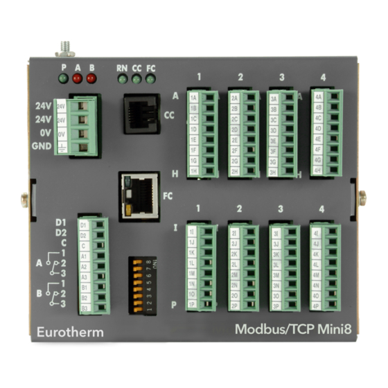
Page 20: Ethernet (Modbus Tcp)
Engineering Handbook Mini8 Controller 1.4.10 Ethernet (Modbus TCP) The Ethernet connection uses standard Cat5E patch cables (RJ45). These would be used with a 10BaseT hub to create a network. A crossover patch cable may be used ‘point-to-point’ i.e. to connect a single instrument directly to a PC. Connector: RJ45: Function Network traffic activity is displayed on indicators built into the connector, yellow indicates network activity and... -
Page 21: Thermocouple Input Tc4 And Tc8
Mini8 Controller Engineering Handbook 1.4.11 Thermocouple Input TC4 and TC8 The TC8 thermocouple module takes 8 thermocouples; the TC4 module takes 4 thermocouples. They may be placed in any slot in the Mini8 controller. Up to 4 may be fitted in a Mini8 controller. Each input can be configured to any thermocouple type or a linear mV input. -
Page 22: Rtd / Pt100 Input Rt4
Engineering Handbook Mini8 Controller 1.4.12 RTD / PT100 Input RT4 The RT4 module provides 4 RTD inputs for 2, 3 or 4 wire connections. Up to 4 modules may be fitted in a Mini8 controller and they may be placed in any slot. Each input can be configured for any resistive sensor up to 600 ohms. -
Page 23: Logic Input Di8
Mini8 Controller Engineering Handbook 1.4.13 Logic Input DI8 The DI8 module provides 8 logic inputs. They may be placed in any slot in the Mini8 controller. Up to 4 may be fitted in a Mini8 controller. Ø D1 + +24V Ø... -
Page 24: Logic Output Do8
Engineering Handbook Mini8 Controller 1.4.14 Logic Output DO8 The DO8 module provides 8 logic outputs. They may be placed in any slot in the Mini8 controller. Up to 4 may be fitted in a Mini8 controller. Each output can be configured to Time Proportioning or On/Off. Ø... -
Page 25: Relay Output Rl8
Mini8 Controller Engineering Handbook 1.4.15 Relay Output RL8 The RL8 module provides 8 relay outputs. Up to 2 modules may be fitted and in slots 2 and/or 3 only RLY1 A Ø RLY1 B Ø RLY2 A Ø RLY2 B Ø... -
Page 26: Analogue Output Ao4 And Ao8
Engineering Handbook Mini8 Controller 1.4.16 Analogue Output AO4 and AO8 The AO8 modules provides 8 analogue outputs and the AO4 provides 4 analogue outputs. Each output is configurable within 0 to 20 mA , max load 360 ohm. The AO4 offers OP1 to OP4 on terminals A to H. Only one module may be fitted and in slot 4 only. -
Page 27: Current Transformer Input Module Ct3
Mini8 Controller Engineering Handbook 1.4.17 Current Transformer input Module CT3 This provides inputs for 3 current transformers. The heater load cables are threaded through the transformers. Each input is 50mA max into 5 ohms. Ø Reserved Ø Reserved Ø Reserved Ø... -
Page 28: Adding Or Replacing An Io Module
Engineering Handbook Mini8 Controller Adding or replacing an IO module. Modules contain static sensitive electronic devices. Take full antistatic protection when replacing modules by working on an earthed mat with an earthed wrist strap. Avoiding touching components, keep fingers on the green connectors or the edge of the printed circuit boards. Remove screw →... -
Page 29: Mini 8 Led Indicators
Mini8 Controller Engineering Handbook Mini 8 LED Indicators Two sets of 3 LEDs on the front panel indicate the power, the state of the output relays, the status of the Mini8 controller and communications activity. Legend Green Function Indicates 24V Relay A state Relay B state No power... -
Page 30: Status Indication For Enhanced Devicenet
Engineering Handbook Mini8 Controller 1.6.1 Status Indication for Enhanced DeviceNet If an Enhanced DeviceNet module is fitted (section 1.4.7), two bi-colour LEDs are NET MOD used to indicate Module and Network status. These two LEDs replace the single LED shown as FC on other modules. See previous section. -
Page 31: Chapter 2 Using The Mini8 Controller
OPCLink. In this situation the user would not have to know any of the parameter addresses, and would just select a parameter by browsing through the namespace. e.g. Eurotherm.ModbusServer.1.COM1.ID001-Mini8.Loop.1.Main.PV Modbus, single register, SCADA addressing The key parameters of the Mini8 controller are available at a fixed single 16 bit register address, independent of its configuration. -
Page 32: Modbus (Floating Point)
Engineering Handbook Mini8 Controller Modbus (Floating Point) If the application requires the extra resolution, the Commstab folder also offers an alternative solution where a parameter can be indirectly addressed and communicated either as a floating point or as a double integer value –... -
Page 33: The Itools Operator Interface
The iTools handbook, part no. HA026179, provides further step by step instructions on the general operation of iTools. This and the iTools software may be downloaded from www.eurotherm.co.uk. When an instrument is found on the network it will be shown as, for example ‘COM1.ID001-Min8’... - Page 34 Engineering Handbook Mini8 Controller To view or change a parameter: Highlight the folder Press to get the parameter window or open up the parameter list by clicking on the required folder. Right click in the parameter list to reveal or hide columns. To change the value of a parameter, click the parameter value, write in the new value.
-
Page 35: Recipe Editor
Mini8 Controller Engineering Handbook Recipe Editor Press for this feature. Up to 8 recipes can be stored. They can also be named by the user. Recipes allow the operator to change the operating values of up to 24 parameters in an instrument for different batch items/processes by simply selecting a particular recipe to load. -
Page 36: Opcscope
Excel. With iTools open OPC Scope can be started using the icon But it can also be started on its own using the Windows Start/Programs/Eurotherm iTools/OPC Scope Select Server/Connect or click the icon and the OPC server will start up (if it is not running) and will display the active ports on the computer. -
Page 37: Opc Scope List Window Context Menu
If you have iTools Open (not iTools Standard) then OPC Scope can run on a remote networked computer. Enter the name of the server computer (attached to the instruments) the ‘Computer’ window and browse for the ‘Eurotherm.ModbusServer1’. 2.9.2 OPC Scope Chart Window Click the Chart tab at the bottom of the display window and select Chart Control Panel. - Page 38 Engineering Handbook Mini8 Controller iTools Trend Graph showing Loop1 SP and PV icon allows the chart to occupy all the window space. Part No HA028581 Issue 7.0 Dec-09...
-
Page 39: Opc Server
OPC Server ITools and OPC Scope all use the Eurotherm OPC Server to provide the connection between the instruments and the computer displays. When you ‘scan’ for instruments on iTools it is in fact the OPC Server that is actually doing the work in background (the window is not usually displayed). -
Page 40: Chapter 3 Configuration Using Itools
RJ11 port connecting to a serial port on the PC. Alternatively a Configuration Clip is available from Eurotherm that can be fitted into the rear of the controller. The benefit of using this arrangement is that it is not necessary to power the controller, since the clip provides the power to the internal memory of the controller. -
Page 41: Cloning
Mini8 Controller Engineering Handbook Cloning Saving a Clone File On the iTools menu ‘File – Save to File’ allows the clone file of the attached Mini8 controller to be saved to disc as <user name>.UIC file. This can be loaded into another Mini8 controller. Note that after synchronization iTools using uses a ‘quick’... -
Page 42: Configuring The Mini8 Controller
Engineering Handbook Mini8 Controller Configuring the Mini8 Controller Once iTools is successfully connected to a Mini8 controller, it can be configured for the application in hand. Configuration involves selection of the required elements of functionality called ‘function blocks’ and setting their parameters to the correct values. -
Page 43: Soft Wiring
Mini8 Controller Engineering Handbook 3.4.2 Soft Wiring Soft Wiring (sometimes known as User Wiring) refers to the connections that are made in software between function blocks. Soft wiring, which will generally be referred to as ‘Wiring’ from now on is created during the instrument configuration using the iTools configuration package. -
Page 44: Simple Worked Example
Engineering Handbook Mini8 Controller Simple Worked Example Using function blocks and wiring the following sections will show a blank Mini8 controller being configured to have one PID loop. 3.5.1 The I/O With the Mini8 controller successfully connected to iTools configuration can begin. ☺... - Page 45 Mini8 Controller Engineering Handbook Figure 3-4: Thermocouple Input Select the I/O type, linearisation, units, resolution etc. required. Parameter details are in Section 7.5. The other thermocouple channels can be found by using the 2, 3, 4…7, 8 tabs on the top of the parameter window.
- Page 46 Engineering Handbook Mini8 Controller Example 2: RTD Input Configuration In the IO list ModIDs select the type of module. RTD modules are 4 input modules [RT4Mod (173)]. Figure 3-6: Mini8 Controller IO Module1 Defined as RTD RTDs can be defined as 2-wire [RTD2 (32)], 3-wire [RTD3 (33)] or 4-wire [RTD4 (34)] in the module definition list. It is important that the ‘IO Type’...
- Page 47 Mini8 Controller Engineering Handbook 3.5.2 Wiring The IO that has been configured now needs to be wired to PID loops and other function blocks. Select (GWE) to create and edit instrument wiring. The Graphical Wiring Editor window To add a function block drag it from the list and drop it on this editor.
- Page 48 Engineering Handbook Mini8 Controller Use drag and drop to select the first thermocouple from IOMod 1, the Cool output from IOMod 17 and the Heat output from IOMod 25 and drop them on the wiring window. Finally take the first PID block from Loop/Loop 1 and drop it on the wiring window. Note that as each block is used it greys out on the list.
- Page 49 Mini8 Controller Engineering Handbook Figure 3-10: PID Function Block This enables the PID function block to be set up to suit the required application. See Chapter 17 for details. Click on the instrument button to download the application: Once downloaded the dotted lines around the function blocks and the wires will become solid to show that the application is now in the Mini8 controller.
-
Page 50: Graphical Wiring Editor
Engineering Handbook Mini8 Controller Graphical Wiring Editor Select (GWE) to view and edit instrument wiring. You can also add comments and monitor parameter values. Drag and drop required function blocks into the graphical wiring from the list in the left pane Click on parameter to be wired from and drag the wire to the parameter to be wired to (do not hold mouse button down) Right click to edit parameter values... -
Page 51: Graphical Wiring Toolbar
Mini8 Controller Engineering Handbook 3.6.1 Graphical Wiring Toolbar Download Grab & Pan Pan Drawing Delete, Undo & Redo Copy a Diagram Fragment to a File Copy Paste a Diagram Fragment to a File Create a Compound IO Setup Select Zoom Drawing Grid on/off Paste 3.6.2... -
Page 52: Tooltips
Engineering Handbook Mini8 Controller 3.6.5.1 Function Block Context Menu Right clicking displays the context menu with the following entries. Function Block Brings up an iTools parameter list which shows all the parameters in the function block. If the block has View…... -
Page 53: Function Block State
Mini8 Controller Engineering Handbook 3.6.7 Function Block State The blocks are enabled by dragging the block onto the diagram, wiring it up, and downloading it to the instrument When the block is initially dropped onto the diagram it is drawn with dashed lines. When in this state the parameter list for the block is enabled but the block itself is not executed by the instrument. -
Page 54: Using Wires
Engineering Handbook Mini8 Controller 3.6.8 Using Wires 3.6.8.1 Making A Wire Between Two Blocks • Drag two blocks onto the diagram from the function block tree. • Start a wire by either clicking on a recommended output or clicking on the icon at the bottom right corner of the block to bring up the connection dialog. -
Page 55: Using Comments
Mini8 Controller Engineering Handbook 3.6.8.3 Wire Colours Wires can be the following colours: Black Normal functioning wire. The wire is connected to an input which is not alterable when the instrument is in operator mode and so values which travel along that wire will be rejected by the receiving block Blue The mouse is hovering over the wire, or the block to which it is connected it selected. -
Page 56: Using Monitors
Engineering Handbook Mini8 Controller 3.6.10 Using Monitors Drag a monitor onto the diagram and connect it to a block input or output or a wire as described in ‘Using Comments’. The current value (updated at the iTools parameter list update rate) will be shown in the monitor. By default the name of the parameter is shown, double click or use the context menu to not show the parameter name. -
Page 57: Colours
Mini8 Controller Engineering Handbook 3.6.13 Colours Items on the diagram are coloured as follows: Function blocks, comments and monitors which partially obscure or are partially obscured by other items are drawn red. If a large function block like the loop is covering a small one like a math2 the loop will be drawn red to show that it is covering another function block. -
Page 58: Wiring Floats With Status Information
Engineering Handbook Mini8 Controller 3.6.15 Wiring Floats with Status Information There is a subset of float values which may be derived from an input which may become faulty for some reason, e.g. sensor break, over-range, etc. These values have been provided with an associated status which is automatically inherited through the wiring. -
Page 59: Edge Wires
Mini8 Controller Engineering Handbook 4: Up Scale The measurement will be forced to adopt its high limit. This is like having a resistive pull up on an input circuit. In addition the status of the measured value will be set to ‘BAD’, such that any function block using this measurement can operate its own fallback strategy. -
Page 60: Chapter 4 Mini8 Controller Overview
Engineering Handbook Mini8 Controller Chapter 4 Mini8 controller Overview Input and output parameters of function blocks are wired together using software wiring to form a particular control strategy within the Mini8 controller. An overview of all the available functions and where to get more detail is shown below. -
Page 61: Complete List Of Function Blocks
If a particular block or blocks do not appear in your instrument then the option has not been ordered. Check the order code of your instrument and contact Eurotherm. Examples of features that may not have been enabled are: Loops... -
Page 62: Chapter 5 Access Folder
Engineering Handbook Mini8 Controller Chapter 5 Access Folder Folder: Access Sub-folder: none Name Parameter Value Default Access Description Level Disabled ClearMemory Cold start the Conf Mini8 controller memory reset but comms and instrument linearisation tables retained LinTables Custom Linearisation tables are deleted InitComms Comms ports reset to default configurations Wires... -
Page 63: Chapter 6 Instrument Folder
Mini8 Controller Engineering Handbook Chapter 6 Instrument Folder Instrument / Enables The following table lists the options that can be enabled in the instrument. Enable flags are one bit for each item – i.e.Bit (0=1) enables item 1, Bit 1 (=2) item 2, Bit(3=4) item 3 and so on to Bit7(=128) enables Item 8. -
Page 64: Instrument Options
Engineering Handbook Mini8 Controller Folder: Instrument Sub-folder: Enables Name Parameter Description Value Default Access Level Poly En Polynomial linearisation Poly Linearisation 1 and 2 0 (none) to 3 (both) Conf block Enable Flags Prog En Programmer Enable Flags 0 = off, 1 to 8 0 (none) to 255 (all 8) Conf RTClock En... -
Page 65: Instrument / Diagnostics
Mini8 Controller Engineering Handbook Instrument / Diagnostics This list provides fault finding diagnostic information as follows:- Folder: Sub-folder: Diagnostics Instrument Name Parameter Description CPUFree This is the amount of free CPU Time left. It shows the percentage of the tasks ticks that are idle. MinCPUFree A benchmark of the lowest reached value of the CPU free percentage. - Page 66 Engineering Handbook Mini8 Controller Folder: Sub-folder: Diagnostics Instrument Name Parameter Description CommsStack Comms Stack Free Space (words) The number of words of un-used stack for the comms task IdleStack Idle Stack Free Space (words) The number of words of un-used stack for the idle (background) task. Max segments Max number of setpoint programmer segments available MaxSegsPerProg...
-
Page 67: Chapter 7 I/O Folder
Mini8 Controller Engineering Handbook Chapter 7 I/O Folder This lists the modules fitted into the instruments, all the IO channels, the fixed IO and the current monitoring. The IO folder lists all the channels of each of the IO boards in the 4 available slots. Each board has up to 8 inputs or outputs making a maximum of 32 channels. -
Page 68: Logic Input
Engineering Handbook Mini8 Controller Logic Input Each DI8 card provides 8 logic input channels (voltage controlled) to the system. These can be wired to provide digital inputs to any function block within the system. 7.2.1 Logic Input Parameters Folder – IO Sub-folder Mod.1 to .32 Name Parameter Description... -
Page 69: Logic Output
Mini8 Controller Engineering Handbook Logic Output If a slot is fitted with a DO8 board then 8 channels will be available to be configured and connected to Loop outputs, alarms or other logic signals. 7.3.1 Logic Out Parameters Folder – IO Sub-folder Mod.1 to .32 Name Parameter Description... -
Page 70: Logic Output Scaling
Engineering Handbook Mini8 Controller 7.3.2 Logic Output Scaling If the output is configured for time proportioning control, it can be scaled such that a lower and upper level of PID demand signal can limit the operation of the output value. By default, the output will be fully off for 0% power demand, fully on for 100% power demand and equal on/off times at 50% power demand. -
Page 71: Relay Output
Mini8 Controller Engineering Handbook Relay Output If slot 2 and/or 3 is fitted with a RL8 board then 8 channels will be available to be configured and connected to Loop outputs, alarms or other logic signals. 7.4.1 Relay Parameters Folder – IO Sub-folder Mod.9 to .24 Name Parameter Description... -
Page 72: Thermocouple Input
Engineering Handbook Mini8 Controller Thermocouple Input A TC4 offers 4 channels and the TC8 board offers 8 channels which may be configured as thermocouple inputs or mV inputs. 7.5.1 Thermocouple Input Parameters Folder – IO Sub-headers: Mod .1 to .32 Name Parameter Description Value... - Page 73 Mini8 Controller Engineering Handbook Folder – IO Sub-headers: Mod .1 to .32 Name Parameter Description Value Default Access Level Fallback PV Fallback value Instrument range Conf See also section 7.5.5. Filter Time Input filter time. Off to 500:00 (hhh:mm) 1s600ms Oper Constant An input filter provides damping of the...
-
Page 74: Linearisation Types And Ranges
Engineering Handbook Mini8 Controller 7.5.2 Linearisation Types and Ranges Input Type Min Range Max Range Units Min Range Max Range Units Thermocouple type J -210 1200 -238 2192 Thermocouple type K -200 1372 -238 2498 Thermocouple type L -200 -238 1652 Thermocouple type R 1700... -
Page 75: Sensor Break Value
Mini8 Controller Engineering Handbook 7.5.3.4 Isothermal Systems The thermocouple junctions being referenced are contained in a block which is heavily thermally insulated. The junctions are allowed to follow the mean ambient temperature, which varies slowly. This variation is accurately sensed by electronic means, and a signal is produced for the associated instrumentation. The high reliability factor of this method has favoured its use for long term monitoring. -
Page 76: User Calibration (Two Point)
Engineering Handbook Mini8 Controller 7.5.6 User Calibration (Two Point) All ranges of the controller have been calibrated against traceable reference standards. However in a particular application it may be necessary to adjust the displayed reading to overcome other effects within the process. A two point calibration is offered allowing offset and slope adjustment. -
Page 77: Using Tc4 Or Tc8 Channel As A Mv Input
Mini8 Controller Engineering Handbook 7.5.8 Using TC4 or TC8 channel as a mV input Example – a pressure sensor provides 0 to 33mV for 0 to 200 bar. Set IO type as mV Set the Linearisation Type as Linear Set DisplayHigh to 200 (bar) Set DisplayLow to 0 (bar) Set RangeHigh to 33 mV Set RangeLow to 0 mV... -
Page 78: Resistance Thermometer Input
Engineering Handbook Mini8 Controller Resistance Thermometer Input The RT4 module offers 4 resistance inputs which can be linear or PT100. 7.6.1 RT Input Parameters Folder – IO Sub-headers: Mod .1 to .32 Name Parameter Description Value Default Access Level Ident Channel Ident RTinput Read Only... -
Page 79: Linearisation Types And Ranges
Mini8 Controller Engineering Handbook Folder – IO Sub-headers: Mod .1 to .32 Name Parameter Description Value Default Access Level Offset Used to add a constant offset to the PV Instrument range Oper see section 7.5.7 SBrk Value Sensor break Value Used for diagnostics only, and displays the sensor break trip value Cal State... -
Page 80: Analogue Output
Engineering Handbook Mini8 Controller Analogue Output The AO4 offers 4 channels and the AO8 module 8 channels which maybe configured as mA outputs. An AO4 or AO8 may only be fitted in Slot 4. Folder – IO Sub-folder: Mod.25 to Mod.32 Name Parameter Description Value... -
Page 81: Fixed Io
Mini8 Controller Engineering Handbook Fixed IO There are two digital inputs, designated D1 and D2. Folder: IO Sub-folder: Fixed IO.D1 and .D2 Name Parameter Value Default Access Description Level Ident Channel Ident LogicIn LogicIn Read Only IO Type IO Type Input Input Read... -
Page 82: Current Monitor
Engineering Handbook Mini8 Controller Current Monitor The Mini8 controller, with a CT3 card, has the capability of detecting failures of up to 16 heater loads by measuring the current flowing through them via 3 current transformer inputs. The failures that can be detected are: SSR Fault If current is detected flowing through the heater when the controller is requesting it to be off then this indicates... -
Page 83: Single Phase Configurations
Mini8 Controller Engineering Handbook 7.9.2 Single Phase Configurations 7.9.2.1 Single SSR triggering With this configuration, failures of individual heater loads can be detected. For example, if the current detected flowing through Heater 3 is less than its PLF threshold then this will be indicated as Load3PLF Example1 –... - Page 84 Engineering Handbook Mini8 Controller 7.9.2.2 Multiple SSR triggering With this configuration, failure of a set of heater loads can be detected. For example, if the current detected flowing through Heater Set 1 is less than Load1’s PLF threshold then this will be indicated as Load1PLF. Further investigation will then be required to determine which heater within Set 1 has failed.
-
Page 85: Three Phase Configuration
Mini8 Controller Engineering Handbook 7.9.3 Three Phase Configuration Configuration for Three Phase supply applications is similar to that for Single phase using three CT inputs All currents passed through an individual CT must come from the same MINI8 phase controller Star with neutral or delta N/Ph2 connection is possible... -
Page 86: Parameter Configuration
Engineering Handbook Mini8 Controller 7.9.4 Parameter Configuration If Current Monitor is enabled in the folder Instrument/Options/Current Monitor then the current monitor configuration folder appears as a subfolder in IO. Folder: IO Sub-folder: CurrentMonitor/Config Name Parameter Value Default Access Description Level See section 7.9.5 Commission Commission CT... -
Page 87: Commissioning
Mini8 Controller Engineering Handbook 7.9.5 Commissioning 7.9.5.1 Auto Commission Auto commissioning of the Current Monitor is a feature that automatically detects which time proportioning outputs drive individual heaters (or heater sets), detects which CT input individual heaters are associated with and determines the Partial Load and Over Current thresholds using a 1:8 ratio. - Page 88 Engineering Handbook Mini8 Controller 7.9.5.2 Manual Commission Manual Commissioning is also available and is intended for those users who want to commission the Current Monitor off-line or do not want to accept auto commissioned settings. How to Manual Commission Set Commission to Manual. CommissionStatus will display Commissioning and Load1 configuration parameters will become available Set Load1DrivenBy to the IO Module that is connected to the heater load.
-
Page 89: Calibration
Mini8 Controller Engineering Handbook 7.9.6 Calibration A Mini8 controller supplied from factory with the CT3 card already installed the CT inputs will have been factory calibrated. If the CT3 card is installed at a later date then default calibration values are automatically loaded into the instrument. -
Page 90: Chapter 8 Alarms
Engineering Handbook Mini8 Controller Chapter 8 Alarms Alarms are used to alert the system when a pre-set level has been exceeded or a particular condition has changed state. As the Mini8 controller has no display to show alarms the alarm flags are all available over communications in status words See Alarm Summary (Section 8.7). -
Page 91: Analogue Alarms
Mini8 Controller Engineering Handbook Analogue Alarms Analogue alarms operate on variables such as PV, output levels, etc. They can be soft wired to these variables to suit the process. 8.2.1 Analogue Alarm Types Absolute High - an alarm occurs when the PV exceeds a set high threshold. Absolute Low - an alarm occurs when the PV exceeds a set low threshold. -
Page 92: Digital Alarms
Engineering Handbook Mini8 Controller Digital Alarms Digital alarms operate on Boolean variables. They can be soft wired to any suitable Boolean parameter such as digital inputs or outputs. 8.3.1 Digital Alarm Types Pos Edge The alarm will trigger when the input changes from a low to high condition Neg Edge The alarm will trigger when the input changes from a high to low condition Edge... -
Page 93: Alarm Parameters
Mini8 Controller Engineering Handbook Alarm Parameters Four groups of eight analogue alarms are available. The following table shows the parameters to set up and configure alarms. Folder: Alarm Sub-folders: 1 to 32 Name Parameter Description Value Default Access Level Type Selects the type of alarm None Alarm not configured... -
Page 94: Example: To Configure Alarm 1
Engineering Handbook Mini8 Controller 8.5.1 Example: To Configure Alarm 1 Change Access level to configuration. In this example the high alarm will be detected when the measured value exceeds 100.00. The current measured value is 27.79 as measured by the ‘Input’ parameter. This parameter will normally be wired to an internal source such as a thermocouple input. -
Page 95: Digital Alarm Parameters
Mini8 Controller Engineering Handbook Digital Alarm Parameters Four groups of eight digital alarms are available. The following table shows the parameters to set up and configure alarms. Folder: DigAlarm Sub-folders: 1 to 32 Name Parameter Description Value Default Access Level Type Selects the type of alarm None... -
Page 96: Alarm Summary
Engineering Handbook Mini8 Controller Alarm Summary This is a summary of all the alarms in the Mini8 controller. It provides global alarm and acknowledge flags as well as 16 bit status words which can be read over communications by the supervisory system. Folder: AlmSummary Sub-folders: General Name... - Page 97 Mini8 Controller Engineering Handbook Folder: AlmSummary Sub-folders: General Name Parameter Description Value Default Access Level DigAlarmStatus1 16 bit word for digital alarms 1 to 8 Bit 0 Alarm 1 active Bit 1 Alarm 1 not ack’d Bit 2 Alarm 2 active Bit 3 Alarm 2 not ack’d Bit 4...
-
Page 98: Alarm Log
Engineering Handbook Mini8 Controller Folder: AlmSummary Sub-folders: General Name Parameter Description Value Default Access Level CTAlarmStatus2 16 bit word for CT alarms 6 to 10 Bit 0 Load6 SSR fail Bit 1 Load6 PLF Bit 2 Load6 OCF Bit 3 Load7 SSR fail Bit 4 Load7 PLF... -
Page 99: Chapter 9 Bcd Input
Mini8 Controller Engineering Handbook Chapter 9 BCD Input The Binary Coded Decimal (BCD) input function block uses a number of digital inputs and combines them to make a numeric value. A very common use for this feature is to select a setpoint program number from panel mounted BCD decade switches. -
Page 100: Example: To Wire A Bcd Input
Engineering Handbook Mini8 Controller In 1 In 2 In 3 In 4 In 5 In 6 In 7 In 8 Units Tens 9.1.1 Example: To wire a BCD Input The BCD digital input parameters may be wired to digital input terminals of the controller. A DI8 module may be used and there are also two standard digital input terminals in FixedIO, D1 and D2. -
Page 101: Chapter 10 Digital Communications
The configuration port is on an RJ11 socket, just to the right of the power supply connections. This will normally be connected to a personal computer running iTools. Eurotherm supply a standard cable to connect a serial COM port on a computer to the RJ11 socket, part no. SubMini8/cable/config. -
Page 102: Field Communications Port
Engineering Handbook Mini8 Controller When connecting to iTools the instrument on this port will be found at address 255. iTools will also optimise the baud rate to suit the conditions. This port can be used as a ‘permanent’ connection but it is limited to one instrument, it is a RS232 point to point connection. -
Page 103: Communications Parameters
Mini8 Controller Engineering Handbook 10.3.2 Communications Parameters The following table shows the parameters available. Folder – Comms Sub-folder: FC (Field Communications Name Parameter Description Value Default Access Level Ident Comms Module Identity Modbus / DeviceNet/CANopen/Profibus/ Modbus Ethernet Protocol Digital communications protocol MODBUS / DeviceNet/CANopen/Profibus/ MODBUS Conf... -
Page 104: Modbus Address Switch
Engineering Handbook Mini8 Controller 10.3.4 Modbus Address Switch On a network of instruments an address is used to specify a particular instrument. Each instrument on a network MUST have a unique address. Address 255 is reserved for configuration using the configuration port or the configuration clip The switch is situated at the bottom of the Comms module. -
Page 105: Modbus Broadcast Master Communications
Before using this facility, check that the instrument to which you wish to send values can accept continuous writes. Note that in common with many third party lower cost units, the Eurotherm 2200 series and the 3200 series prior to version V1.10 do not accept continuous writes to the temperature setpoint. Damage to the internal non-volatile memory could result from the use of this function. -
Page 106: Wiring Connections
Engineering Handbook Mini8 Controller 10.4.2 Wiring Connections The Digital Communications module for the master must be the Field Comms and is only RS485/RS422. RS232 is not available. The Digital Communications module for the slave can be the Config port (RS232 only) or the Field Comms port (Not RS232). -
Page 107: Devicenet
Mini8 Controller Engineering Handbook 10.5 DeviceNet Only 2 parameters have to be set on the Mini8 controller for use with DeviceNet, baud rate and address. Both can be set on the hardware address switch situated under the DeviceNet connector. Each Mini8 controller must have a unique address on the DeviceNet network and all units must be set to the same Baud rate. -
Page 108: Canopen
Engineering Handbook Mini8 Controller 10.8 CANopen Note: from July 09 CANopen option has been discontinued. 10.8.1 Instrument setup Up to 127 Nodes can be connected to a standard CANopen Network, for nodes 1 – 31 the address can be set via the comms DIP switches. -
Page 109: Communication Interface
Mini8 Controller Engineering Handbook 10.8.3 Communication Interface CANopen is based on communication profiles, which specifies the basic communication mechanisms (PDOs, SDOs and NMT messages) and an object directory that specifies device parameters and functions. 10.8.3.1 Object Dictionary The object dictionary is divided into a section containing general device information (device identification, manufacturer name etc), communication parameters, and a section that describes the specific device data/functionality whether by a device profile (part of CANopen specifications) or manufacturer specified. -
Page 110: Network Management (Nmt)
Engineering Handbook Mini8 Controller 10.8.4 Network Management (NMT) CANopen slave nodes include the following state machine, which allows the slaves to be in different operating states. Initialisation Boot Up FC LED: Off Pre-operational SDO communications Emergency Heartbeat/Node Guard Sync FC LED: blinking Stopped Heartbeat/Node Guard FC LED: Off... -
Page 111: Device Profile Ds-404
IO etc to be associated with different channels. The Mini8 controller is classed as a Generic Device as its CANopen application objects have been specified by Eurotherm using the range from 2000h. 10.8.6 Default PDOs Transmit PDOs are typically used to transmit critical instrument data to other nodes on the network, for example, alarm status’. - Page 112 Engineering Handbook Mini8 Controller 10.8.6.2 Transmit PDO1 This contains the Analogue Alarm Status words. As default it is Enabled and configured to transmit when any of the status word values change. Object Sub Index Parameter Data Type Index 1A00h Number of Supported Entries [4] Unsigned8 AlmSummary.AnAlarmStatus1 Integer16...
- Page 113 Mini8 Controller Engineering Handbook 10.8.6.6 Receive PDO1 This contains control loop Operational parameters, the loop number must be specified in order for the Mini8 controller to set the correct loop instance parameters. Object Sub Index Parameter Data Type Index 1600h Number of Supported Entries [4] Unsigned8 Loop Number [0.…15 corresponding to n=1….16]...
-
Page 114: Enabling And Disabling Pdo Communications
Engineering Handbook Mini8 Controller 10.8.7 Enabling and Disabling PDO Communications The Mini8 controller is supplied with all 8 PDOs enabled. Every PDO has a mapping object and a communication object as shown. The PDO is enabled by resetting the appropriate bit and disabled by setting the appropriate bit. This is done using SDO communications. Mapping Object Communication PDO Enable... - Page 115 Mini8 Controller Engineering Handbook 10.8.8.1 Commstab Example 1 Remap Receive PDO 1 with UsrVal.1-4.Vals: Receive PDO1 from the Object pick list in Appendix C is shown below Object Parameter Data Type SCADA Index Index Address 2000h Receive PDO1 Note: Sub indices 02h – 04h are letter boxed via sub index 01h. Loop Number (Comms.InstNum1) Integer16 15816...
- Page 116 Engineering Handbook Mini8 Controller Enter 15843 as the Modbus Destination, and pick Loop.1.Main.AutoMan for the Source and set LetterBox to Yes. CommsTab Source Modbus Address Pick List Tx PDO 3 Loop.1.Main.AutoMan 15843 2000h 1Ch 1A02h 04h 10.8.8.3 Commstab Example 3 Remap Transmit PDO 3 sub index 04h with UsrVal.3.Val, not using letter boxing so that no matter what the loop instance UsrVal.3.Val will be transmitted: CommsTab Source...
-
Page 117: Remapping Over The Network
Mini8 Controller Engineering Handbook 10.8.9 Remapping over the network 10.8.9.1 Using SDO communications It is possible to remap any of the PDOs with entries from the Pick List using SDO communications. The following procedure must be followed: Disable PDO by setting bit 31 sub index 1 of the PDOs communication object. Deactivate PDO mapping object by writing ‘0’... - Page 118 Engineering Handbook Mini8 Controller 10.8.9.2 Using Device Configuration Software. This shows one step of the example above using configuration software. From the CANopen parameter tables in Appendix C UserVal 1 to 4 have sub-ibex C3h to C6h, or 195 to 198 so delete the existing elements in the Mapped Objects and add elements 195 to 198.
-
Page 119: Enabling & Disabling Pdo Change Of State Transmission
Mini8 Controller Engineering Handbook 10.8.10 Enabling & Disabling PDO Change of State transmission. It is possible to change the way a transmit PDO works – either cyclically or on change of state (COS), or both. Object Index 2002h allows COS transmission of PDOs to be enabled or disabled. Object Index Sub Index Parameter... -
Page 120: Error Register
Engineering Handbook Mini8 Controller 10.8.13 Error Register Index Sub Index Description Value (U32) Bit set = error 1001h Generic Error: Mandatory Bit set = ANY error Current: not supported Voltage: not supported Temperature: not supported Communication Error: Bit set = error Device Profile Defined not supported Error:... - Page 121 Mini8 Controller Engineering Handbook 10.8.14.2 Manufacturer Software Version This will indicate the software version of the instrument firmware. Index Sub Index Description Value (String) 100Ah Formal Release (n: Phase m: Minor Revision) Vn.mm Engineering Release (n: Phase m: Minor Revision) En.mm 10.8.14.3 Store &...
- Page 122 Engineering Handbook Mini8 Controller In order to avoid saving parameters by mistake, saving is only executed when a specific signature is written to sub-index 01h. The signature is “save”: ASCII: Hex: Or Using the IXXAT Node Manager, select ASCII Data and write ‘save’ It should be noted that whilst in the process of saving the parameter data to non-volatile memory it is not possible to write to the parameters that are currently being saved.
- Page 123 Product Code = E800 Revision Number = Bits Description 0 – 15 Minor Revision Number (Initially: 0001h) 16 – 31 Major Revision Number (Initially: 0001h) Serial Number (32-bit interface board number entered by Eurotherm) Part No HA028581 Issue 7.0 Dec-09...
-
Page 124: Profibus
Engineering Handbook Mini8 Controller 10.9 Profibus Up to 127 Nodes can be connected to a Profibus Network and the address is set via the comms DIP switches. The Baud Rate is auto-detected and set by the master. Not Used Address 64 Example shows an address 68 Address 32 Address 16... -
Page 125: Ethernet
Mini8 Controller Engineering Handbook 10.10 Ethernet 10.10.1 Instrument setup It is recommended that you setup the communications settings for each instrument before connecting it to any Ethernet network. This is not essential but network conflicts may occur if the default settings interfere with equipment already on the network. -
Page 126: Itools Setup
Engineering Handbook Mini8 Controller 10.10.3.3 Default Gateway The "Comms" tab also includes configuration settings for "Default Gateway", these parameters will be set automatically when Dynamic IP Addressing is used. When fixed IP addressing is used these settings are only required if the instrument needs to communicate wider than the local area network i.e. over the internet. 10.10.3.4 Preferred Master The "Comms"... -
Page 127: Ethernet Parameters
Mini8 Controller Engineering Handbook 10.10.5 Ethernet Parameters Folder - Comms Sub-folder: FC Name Parameter Description Value Default Access Level Ident Identifies that the comms None No module fitted module is fitted. Comms Communications module fitted Protocol Digital communications protocol MODBUS; Profibus; DeviceNet; Conf Ethernet,CANopen Address... -
Page 128: Counters
Engineering Handbook Mini8 Controller Chapter 11 Counters, Timers, Totalisers, RT Clock A series of function blocks are available which are based on time/date information. These may be used as part of the control process. 11.1 Counters Up to two counters are available. They provide a synchronous edge triggered event counter. Direction Enable Count... -
Page 129: Counter Parameters
Mini8 Controller Engineering Handbook Count = Count = Count = 0 Target -1 Target Clock RippleCarry Overflow Figure 11-3: Timing Diagram for an Up Counter 11.1.1 Counter Parameters Folder - Counter Sub-folders: 1 to 2 Name Parameter Description Value Default Access Level Enable... -
Page 130: Timers
Engineering Handbook Mini8 Controller 11.2 Timers Up to eight timers can be configured. Each one can be configured to a different type and can operate independently of one another. 11.2.1 Timer Types Each timer block can be configured to operate in four different modes. These modes are explained below 11.2.2 On Pulse Timer Mode This timer is used to generate a fixed length pulse from an edge trigger. -
Page 131: On Delay Timer Mode
Mini8 Controller Engineering Handbook 11.2.3 On Delay Timer Mode This timer provides a delay between the trigger event and the Timer output. If the input pulse is less than the set delay time there is no output pulse. The Output is set to Off when the Input changes from Off to On. •... -
Page 132: One Shot Timer Mode
Engineering Handbook Mini8 Controller 11.2.4 One Shot Timer Mode This timer behaves like a simple oven timer. When the Time is edited to a non-zero value the Output is set to On • The Time value is decremented until it reaches zero. The Output is then cleared to Off •... -
Page 133: Minimum On Timer Or Compressor Mode
Mini8 Controller Engineering Handbook 11.2.5 Minimum On Timer or Compressor Mode This timer has been targeted at guaranteeing that the output remains On for a duration after the input signal has been removed. It may be used, for example, to ensure that a compressor is not cycled excessively. The output will be set to On when the Input changes from Off to On. -
Page 134: Timer Parameters
Engineering Handbook Mini8 Controller 11.2.6 Timer Parameters Folder – Timer Sub-folders: 1 to 4 Name Parameter Description Value Default Access Level Type Timer type Conf Timer not configured On Pulse Generates a fixed length pulse from an edge trigger Off Delay Provides a delay between input trigger event and timer putput One Shot... -
Page 135: Totalisers
Mini8 Controller Engineering Handbook 11.3 Totalisers There are two totaliser function blocks which are used to measure the total quantity of a measurement integrated over time. A totaliser can, by soft wiring, be connected to any measured value. The outputs from the totaliser are its integrated value and an alarm state. -
Page 136: Totaliser Parameters
Engineering Handbook Mini8 Controller 11.3.1 Totaliser Parameters Folder – Total Sub-Folders: 1 to 2 Name Parameter Description Value Default Access Level TotalOut The totalised value ±9,999,999,999 The value to be totalised Oper -9999.9 to 9999.9. Note:- the totaliser stops accumulating if the input is ‘Bad’. -
Page 137: Real Time Clock
Mini8 Controller Engineering Handbook 11.4 Real Time Clock A real time clock (day of week and time only) is used to provide a daily and weekly scheduling facility and provides two corresponding outputs. The configuration for an output is an On-Day and an On-Time and an Off- Day and an Off-Time. -
Page 138: Chapter 12 Applications
Engineering Handbook Mini8 Controller Chapter 12 Applications 12.1 Humidity 12.1.1 Overview Humidity (and altitude) control is a standard feature of the Mini8 controller. In these applications the controller may be configured to generate a setpoint profile (see Section 18 ‘Setpoint Programmer’). Also the controller may be configured to measure humidity using either the traditional Wet/Dry bulb method or it may be interfaced to a solid state sensor. -
Page 139: Humidity Parameters
Mini8 Controller Engineering Handbook 12.1.4 Humidity Parameters List Folder – Humidity Sub-folder: None Name Parameter Description Value Default Access Level Resolution Resolution of the relative XXXXX Conf humidity XXXX.X XXX.XX XX.XXX X.XXXX Psychro Const The psychrometric constant at a 0.0 to 10.0 6.66 Oper given pressure (6.66E-4 at... -
Page 140: Zirconia (Carbon Potential) Control
Engineering Handbook Mini8 Controller 12.2 Zirconia (Carbon Potential) Control A Mini8 Controller has a Zirconia function block which may be used to control Carbon potential. The controller is often a programmer which generates carbon potential profiles. In this section it is assumed that a programmer is used. -
Page 141: Zirconia Parameters
Mini8 Controller Engineering Handbook 12.2.8 Zirconia Parameters Folder - Zirconia Sub-folders: None Name Parameter Description Value Default Access Level Probe Type Configures the type of probe to be used Drayton Drayton Accucarb Accucarb MacDhui MacDhui Oxygen LogO2 Log Oxygen BoschO2 Bosch Oxygen ZircoDew Dewpoint. - Page 142 Engineering Handbook Mini8 Controller Folder - Zirconia Sub-folders: None Name Parameter Description Value Default Access Level PvFrozen This is a Boolean which freezes the PV during a purging cycle. It may have been wired, for example, to disable control output during purging CleanValve Enable the clean valve.
-
Page 143: Chapter 13 Input Monitor
Mini8 Controller Engineering Handbook Chapter 13 Input Monitor 13.1 Description There are two Input monitors. Each input monitor may be wired to any variable in the controller. It then provides three functions:- Maximum detect Minimum detect Time above threshold 13.1.1 Maximum Detect This function continuously monitors the input value. -
Page 144: Input Monitor Parameters
Engineering Handbook Mini8 Controller 13.2 Input Monitor Parameters Folder - IPMonitor Sub-Folders: 1 or 2 Name Parameter Description Value Default Access Level The input value to be monitored May be wired to an input source. The range will Oper depend on the source R/O if wired M a x... -
Page 145: Chapter 14 Logic And Maths Operators
Mini8 Controller Engineering Handbook Chapter 14 Logic and Maths Operators. 14.1 Logic Operators Logic Operators allow the controller to perform logical calculations on two input values. These values can be sourced from any available parameter including Analogue Values, User Values and Digital Values. The parameters to use, the type of calculation to be performed, input value inversion and ‘fallback’... -
Page 146: Input Logic Operations
Engineering Handbook Mini8 Controller 14.1.2 2 input Logic Operations The following calculations can be performed: Oper Operator description Input 1 Input 2 Output Invert = 0: OFF The selected logic operator is turned off None 1: AND The output result is ON when both Input 1 and Input 2 are ON 2: OR The output result is ON when either Input... -
Page 147: Logic Operator Parameters
Mini8 Controller Engineering Handbook 14.1.3 Logic Operator Parameters Folder – Lgc2 (2 Input Operators) Sub-Folders: 1 to 24 Name Parameter Description Value Default Access Level Oper To select the type of operator See previous table None Conf Input 1 Normally wired to a logic, analogue or user value. OPER May be set to a constant value if not wired. -
Page 148: Eight Input Logic Operators
Engineering Handbook Mini8 Controller 14.2 Eight Input Logic Operators The eight input logic operator may be used to perform the following operations on eight inputs. Oper Operator description 0: OFF The selected logic operator is turned off 1: AND The output result is ON when ALL eight inputs are ON 2: OR The output result is ON when one or more of the 8 inputs are ON 3: XOR... -
Page 149: Maths Operators
Mini8 Controller Engineering Handbook 14.3 Maths Operators Maths Operators (sometimes known as Analogue Operators) allow the controller to perform mathematical operations on two input values. These values can be sourced from any available parameter including Analogue Values, User Values and Digital Values. Each input value can be scaled using a multiplying factor or scalar. The parameters to use, the type of calculation to be performed and the acceptable limits of the calculation are determined in Configuration level. -
Page 150: Math Operations
Engineering Handbook Mini8 Controller 14.3.1 Math Operations The following operations can be performed: 0: Off The selected analogue operator is turned off 1: Add The output result is the addition of Input 1 and Input 2 2: Subtract (Sub) The output result is the difference between Input 1 and Input 2 where Input 1 >... -
Page 151: Math Operator Parameters
Mini8 Controller Engineering Handbook 14.3.2 Math Operator Parameters Folder – Math2 (2 Input Operators) Sub-Folders: 1 to 24 Name Parameter Description Value Default Access Level Oper To select the type of operator See previous table None Conf In1Mul Scaling factor on input 1 Limited to max float * Oper In2 Mul... -
Page 152: Sample And Hold Operation
Engineering Handbook Mini8 Controller 14.3.3 Sample and Hold Operation The diagram below shows the operation of the sample and hold feature. True False Result Figure 14-4: Sample and Hold Part No HA028581 Issue 7.0 Dec-09... -
Page 153: Multiple Input Operator Block
Mini8 Controller Engineering Handbook 14.4 Multiple Input Operator Block The Multiple Input Operator Block simultaneously outputs the Sum, Average, Minimum and Maximum values of up to 8 valid inputs. The outputs will be clipped to user-defined limits or be replaced by a fallback value based on the selected fallback strategy. -
Page 154: Cascaded Operation
Engineering Handbook Mini8 Controller 14.4.1 Cascaded operation Multiple input operator blocks may be cascaded to allow operations on more than eight inputs (33 max for four instances of the block). shows how two blocks should be configured to find the average of more than eight inputs. -
Page 155: Multiple Input Operator Block Parameters
Mini8 Controller Engineering Handbook 14.4.3 Multiple Input Operator Block Parameters Folder – MultiOper (Multi Operator) Sub-folders: 1 to 4 Name Parameter Description Value Default Access Level NumIn Number of inputs selected to 2 to 8 Config use. CascNumIn Number of cascaded inputs from 0 to 255 the previous block CascIn... -
Page 156: Eight Input Analog Multiplexers
Engineering Handbook Mini8 Controller 14.5 Eight Input Analog Multiplexers The eight Input analogue multiplexers may be used to switch one of eight inputs to an output. It is usual to wire inputs to a source within the controller that selects that input at the appropriate time or event. 14.5.1 Multiple Input Operator Parameters Folder –... -
Page 157: Chapter 15 Input Characterisation
Mini8 Controller Engineering Handbook Chapter 15 Input Characterisation 15.1 Input Linearisation The Lin16 function block converts an input signal into an output PV using a series of up to 15 straight lines to characterise the conversion. The function block provides the following behaviour. The Input values must be monotonic and constantly rising. -
Page 158: Compensation For Sensor Non-Linearities
Engineering Handbook Mini8 Controller Out Low If the input value is outside the translated range then the output status will indicate Bad, Note: and the value will be limited to Out Low > Out the nearest output limit. High The units and resolution parameters will be used for the output values. -
Page 159: Input Linearisation Parameters
Mini8 Controller Engineering Handbook 15.1.2 Input Linearisation Parameters List Folder – Lin16 Sub-folders: 1 to 2 Name Parameter Description Value Default Access Level Units Units of the linearised output None Conf AbsTemp V, mV, A, mA, PH, mmHg, psi, Bar, mBar, %RH, %, mmWG, inWG, inWW, Ohms, PSIG, %O2, PPM, %CO2, %CP, %/sec, RelTemp... -
Page 160: Polynomial
Engineering Handbook Mini8 Controller 15.2 Polynomial Folder – Poly Sub-Folders: 1 to 2 Name Parameter Description Value Default Access Level LinType To select the input type. J , K, L, R, B, N, T, S, PL2, C, PT100, Conf The linearisation type selects which of the Linear, SqRoot instruments linearisation curves is applied to the input signal. - Page 161 Mini8 Controller Engineering Handbook Folder – Poly Sub-Folders: 1 to 2 Name Parameter Description Value Default Access Level Status Indicates the status of the linearised output: Good Good indicates the value is within range and the input is not in sensor break. Indicates the Value is out of range or the input is in...
-
Page 162: Chapter 16 Load
Engineering Handbook Mini8 Controller Chapter 16 Load The load simulation block provides styles of load which can be used to allow an instrument configuration to be tested before connection to the process plant. In the current issue of firmware the simulated loads available are Oven and Furnace. - Page 163 Mini8 Controller Engineering Handbook Folder – Load Sub-Folders: None Name Parameter Description Value Default Access Level LoopOutCh2 Loop output channel 2 input. Oper The output of the loop as wired to the load simulation, this is the power requested of the load.
-
Page 164: Chapter 17 Control Loop Set Up
Engineering Handbook Mini8 Controller Chapter 17 Control Loop Set Up The Mini8 controller has up to 16 loops of control. Each Loop has two outputs, Channel 1 and Channel 2, each of which can be configured for PID or On/Off. The control function block is divided into a number of sections the parameters of which are all listed under the Folder ‘Loop’. -
Page 165: Loop Parameters - Main
Mini8 Controller Engineering Handbook 17.2 Loop Parameters - Main Folder – Loop.1 to Loop.16 Sub-Folder: Main Name Parameter Description Value Default Access Level AutoMan To select Auto or Manual operation. Auto Automatic (closed loop) Auto Oper operation Manual (output power adjusted by the user) operation The process variable input value. -
Page 166: Types Of Control Loop
Engineering Handbook Mini8 Controller 17.3.1 Types of Control Loop 17.3.1.1 On/Off Control On/Off control simply turns heating power on when the PV is below setpoint and off when it is above setpoint. If cooling is used, cooling power is turned on when the PV is above setpoint and off when it is below. The outputs of such a controller will normally be connected to relays –... -
Page 167: Proportional Term
Mini8 Controller Engineering Handbook 17.4.1 Proportional Term The proportional term, or gain, delivers an output which is proportional to the size of the error signal. It is the range over which the output power is continuously adjustable in a linear fashion from 0% to 100% (for a heat only controller). -
Page 168: Derivative Term
Engineering Handbook Mini8 Controller 17.4.3 Derivative Term Derivative action, or rate, provides a sudden shift in output as a result of a rapid change in error, whether or not this is caused by PV alone (derivative on PV) or on SP changes as well (derivative on error selection). If the measured value falls quickly derivative provides a large change in output in an attempt to correct the perturbation before it goes too far. -
Page 169: High And Low Cutback
Mini8 Controller Engineering Handbook 17.4.4 High and Low Cutback Cutback high ‘CBH’ and Cutback low ‘CBL’ are values that modify the amount of overshoot, or undershoot, that occurs during large step changes in PV (for example, under start-up conditions). They are independent of the PID terms which means that the PID terms can be set for optimal steady state response and the cutback parameters used to modify any overshoot which may be present. -
Page 170: Loop Break
Engineering Handbook Mini8 Controller 17.4.7 Loop Break The loop is considered to be broken if the PV does not respond to a change in the output in a given time. Since the time of response will vary from process to process the Loop Break Time (LBT – PID list) parameter allows a time to be set before a Loop Break Alarm (Lp Break - Diag list) is initiated. -
Page 171: Gain Scheduling
Mini8 Controller Engineering Handbook 17.4.9 Gain Scheduling Gain scheduling is the automatic transfer of control between one set of PID values and another. It may be used in very non-linear systems where the control process exhibits large changes in response time or sensitivity, see diagram below. -
Page 172: Pid Parameters
Engineering Handbook Mini8 Controller 17.4.10 PID Parameters Control loops must be specifically ordered – Order Code MINI8 – 4LP, 8LP or 16LP. To enable a loop place one of the Loop function blocks on the graphical wiring page. Folder – Loop Sub-folders: Loop1.PID to Loop16.PID Name Parameter Description... -
Page 173: Tuning Function Block
Mini8 Controller Engineering Handbook 17.5 Tuning Function Block Tuning involves setting the following parameters. Proportional Band ‘PB’, Integral Time ‘Ti’, Derivative Time ‘Td’, Cutback High ‘CBH’, Cutback Low ‘CBL’, and Relative Cool Gain ‘R2G’ (applicable to heat/cool systems only). The controller is shipped with these parameters set to default values. In many cases the default values will give adequate stable straight line control, however, the response of the loop may not be ideal. -
Page 174: Multi-Zone Applications
Engineering Handbook Mini8 Controller Heat/Cool Deadband. In controllers fitted with a second (cool) channel a parameter ‘Ch2 DeadBand’ is also available in the Loop OP folder, section 17.7, which sets the distance between the heat and cool proportional bands. The default value is 0% which means that heating will turn off at the same time as cooling turns on. The deadband may be set to ensure that there is no possibility of the heat and cool channels being on together, particularly when cycling output stages are installed. -
Page 175: Automatic Tuning
Mini8 Controller Engineering Handbook 17.5.4 Automatic Tuning Auto Tune automatically sets the following parameters:- Proportional Band ‘PB’ If ‘Ti’ and/or ‘Td’ is set to OFF, because you wish to use PI, PD or P only control, Integral Time ‘Ti’ these terms will remain off after an autotune. Derivative Time ‘Td’... -
Page 176: Tune Parameters
Engineering Handbook Mini8 Controller 17.5.5 Tune Parameters Folder – Loop.Loop.1 to Loop.16 Sub-folder: Tune Name Parameter Description Value Default Access Level AutoTune To start self tuning Stop Stop Oper Enable Start OutputHigh Set this to limit the maximum Between Low Output and 100.0 !00.0 Oper Limit... -
Page 177: Autotune And Sensor Break
Mini8 Controller Engineering Handbook a. Select the loop to be tuned, b. Set AutoTune Enable to On A One-shot Tune can be performed at any time, but normally it is performed only once during the initial commissioning of the process. However, if the process under control subsequently becomes unstable (because its characteristics have changed), it may be necessary to tune again for the new conditions. -
Page 178: Autotune From Below Sp – Heat/Cool
Engineering Handbook Mini8 Controller 17.5.11 Autotune from Below SP – Heat/Cool The point at which Automatic tuning is performed (Tune Control Point) is designed to operate just below the setpoint at which the process is normally expected to operate (Target Setpoint). This is to ensure that the process is not significantly overheated or overcooled. -
Page 179: Autotune From Below Sp – Heat Only
Mini8 Controller Engineering Handbook 17.5.12 Autotune From Below SP – Heat Only The sequence of operation for a heat only loop is the same as that previously described for a heat/cool loop except that the sequence ends at ‘F’ since there is no need to calculate ‘R2G’. At ‘F’... -
Page 180: Autotune At Setpoint – Heat/Cool
Engineering Handbook Mini8 Controller 17.5.13 Autotune at Setpoint – Heat/Cool It is sometimes necessary to tune at the actual setpoint being used. This is allowable in Mini8 Controller and the sequence of operation is described below. Pk to Pk Hysteresis Target Setpoint High Output Zero Output... -
Page 181: Failure Modes
Mini8 Controller Engineering Handbook 17.5.14 Failure Modes The conditions for performing an autotune are monitored by the parameter ‘State’ (Tune folder). If autotune is not successful error conditions are read by this parameter as follows:- Timeout This will occur if any one stage is not completed within one hour. It could be due to the loop being open or not responding to the demands from the controller. -
Page 182: Manual Tuning
Engineering Handbook Mini8 Controller 17.5.15 Manual Tuning If for any reason automatic tuning gives unsatisfactory results, you can tune the controller manually. There are a number of standard methods for manual tuning. The one described here is the Ziegler-Nichols method. Adjust the setpoint to its normal running conditions (it is assumed this will be above the PV so that heat only is applied) Set the Integral Time ‘Ti’... -
Page 183: Manually Setting The Cutback Values
Mini8 Controller Engineering Handbook 17.5.17 Manually Setting the Cutback Values Enter the PID terms calculated from the table in section 17.5.15 before setting cutback values. The above procedure sets up the parameters for optimum steady state control. If unacceptable levels of overshoot or undershoot occur during start-up, or for large step changes in PV, then manually set the cutback parameters. -
Page 184: Setpoint Function Block
Engineering Handbook Mini8 Controller 17.6 Setpoint Function Block For each of the 16 loops, the controller setpoint is the Working Setpoint that may come from a number of alternative sources. This is the value ultimately used to control the process variable in each loop. The working setpoint may be derived from:- SP1 or SP2, both of which are individually set, can be selected by an external signal or via the SPSelect parameter over communications. -
Page 185: Sp Tracking
Mini8 Controller Engineering Handbook 17.6.2 SP Tracking When setpoint tracking is enabled and the local setpoint is selected, the local setpoint is copied to ‘TrackSP’. Tracking now ensures that the alternate SP follows or tracks this value. When the alternate setpoint is selected it initially takes on the tracked value thus ensuring that no bump takes place. - Page 186 Engineering Handbook Mini8 Controller Folder – Loop.1 to Loop.16 Sub-folder: SP Name Parameter Description Value Default Access Level RateDone Flag which indicates when the setpoint is Setpoint changing changing or completed Complete Rate Disable Setpoint rate disable Enabled Oper Disabled SP Trim Trim is an offset added to the setpoint.
-
Page 187: Setpoint Limits
Mini8 Controller Engineering Handbook 17.6.6 Setpoint Limits The setpoint generator provides limits for each of the setpoint sources as well as an overall set of limits for the loop. These are summarised in the diagram below. Range High SPTrim SP HighLimit HighLimit LoopAlm TgtSP... -
Page 188: Setpoint Tracking
Engineering Handbook Mini8 Controller 17.6.8 Setpoint Tracking The setpoint used by the controller may be derived from a number of sources. For example:- Local setpoints SP1 and SP2. These may be selected using the parameter ‘SP Select’ in the SP folder, through digital communications or by configuring a digital input which selects either SP1 or SP2. -
Page 189: Output Function Block
Mini8 Controller Engineering Handbook 17.7 Output Function Block The output function block allows you to set up output conditions from the control block, such as output limits, hysteresis, output feedforward, behaviour in sensor break, etc. Folder – Loop.1 to Loop.16 Sub-folder: OP Name Parameter Description... - Page 190 Engineering Handbook Mini8 Controller Folder – Loop.1 to Loop.16 Sub-folder: OP Name Parameter Description Value Default Access Level Step On transition to manual the output will be the manual op value as last set by the operator ManualOutVal The output when the loop is in manual. Between output Hi and Output Lo Note: In manual mode the controller will still limit the maximum power to the power...
-
Page 191: Output Limits
Mini8 Controller Engineering Handbook 17.7.1 Output Limits The diagram shows where output limits are applied. PID List Including Gain Scheduling output limits OPHi +100 Diag List OPLo -100 OPHi2 +100 Output SchedOPHi Level 3 SchedOPLo Diagnostics Writable NOT Wireable Read only OPLo2 -100 OPHi3 +100 Writable NOT... -
Page 192: Output Rate Limit
Engineering Handbook Mini8 Controller 17.7.2 Output Rate Limit The output rate limiter is a simple rate of change limiter which will prevent the control algorithm demanding step changes in output power. It may be set in percent per second. The rate limit is performed by determining the direction in which the output is changing, and then incrementing or decrementing the Working Output (‘ActiveOut’... -
Page 193: Feedforward
Mini8 Controller Engineering Handbook 17.7.5 Feedforward Feedforward is a value, which is scaled and added to the PID output, before any limiting. It can be used for the implementation of cascade loops or constant head control. Feedforward is implemented such that the PID output is limited to trim limits and acts as a trim on a FeedForward Value. -
Page 194: Effect Of Control Action, Hysteresis And Deadband
Engineering Handbook Mini8 Controller 17.7.6 Effect of Control Action, Hysteresis and Deadband For temperature control ‘Loop.1.Control Action’ will be set to ‘ ’. For a PID controller this means that Reverse the heater power decreases as the PV increases. For an on/off controller output 1 (usually heat) will be on (100%) when PV is below the setpoint and output 2 (usually cool) will be on when PV is above the setpoint Hysteresis applies to on/off control only. -
Page 195: Time To Target Programmer
Mini8 Controller Engineering Handbook Chapter 18 Setpoint Programmer In a setpoint programmer you can set up a profile in the controller in which the setpoint varies in a pre- determined way over a period of time. Temperature is a very common application where it is required to ‘ramp’ the process value from one level to another over a set period of time. -
Page 196: Ramp Rate Programmer
Engineering Handbook Mini8 Controller 18.1.2 Ramp Rate Programmer A ramp rate programmer specifies it's ramp segments as maximum setpoint changes per time unit. Each segment can be specified by the operator as Ramp Rate, Dwell or Step. 1. Ramp Rate – the setpoint changes at a rate in units/time 2. -
Page 197: Segment Types
Mini8 Controller Engineering Handbook 18.3 Segment Types Depending on the type of program configured, a segment may be set as:- 18.3.1 Rate A Ramp segment provides a controlled change of setpoint from an original to a target setpoint. The duration of the ramp is determined by the rate of change specified. Two styles of ramp are possible in the range, Ramp-Rate or Time-To-Target. -
Page 198: Wait
Engineering Handbook Mini8 Controller 18.3.6 Wait Wait specifies the criterion for which a segment cannot proceed to the next segment. Any segment can be defined as ‘Wait’ in the ‘Program Edit’ page. The next parameter is then ‘Wait For’ and here you define the criterion. -
Page 199: Output Events
Mini8 Controller Engineering Handbook 18.4 Output Events Program segments have configurable events. ‘Wait’ ‘GoBack’ and ‘End’ segments do not have events. There are up to 8 digital events, PV Events and Time Events. 18.4.1 Digital Events These are digital flags which can be set on or off for each of the segments. These are enabled by setting Programmer.n.Setup.MaxEvents to the required maximum number of events (>0 and <=8). -
Page 200: Pv Event & User Value
Engineering Handbook Mini8 Controller 18.4.2 PV Event & User Value PV Events are essentially a simplified analogue alarm per segment based on the programmer PV input. For this feature the Programmer.n.Setup.EnablePVEvent must be set to ‘Yes’. The PV Event Output (PVEventOP) may be used to trigger the required response. - Page 201 Mini8 Controller Engineering Handbook The following example of a timed event in segment 3 shows that Programmer.n.Setup.EventOut1 will be on for 10 minutes during segment 3 starting 10 minutes after segment 3 begins. Editing of the Time Events follows a number of simple rules to make programming easier for the operator - these are shown in the 3 diagrams below: Segment TimeEvent = Event1...
- Page 202 Engineering Handbook Mini8 Controller Segment TimeEvent = Event1 TimeEvent = On OffTime >0 OffTime OffTime * = 0 Event Output OnTime=0 OnTime Time Event = Event1 Time Event = Off OffTime Event Output OnTime = 0 Time Event = Event1 TimeEvent = Off OffTime Error : OffTime >...
-
Page 203: Holdback
Mini8 Controller Engineering Handbook 18.5 Holdback Holdback freezes the program if the process value (PV) does not track the setpoint (SP) by more than a user defined amount. The programmer will remain in HOLDBACK until the PV returns to within the requested deviation from setpoint. -
Page 204: Pid Select
Engineering Handbook Mini8 Controller 18.6 PID Select It is possible to set up three sets of PID values, see section 17.4.9. Any one of these sets may be activated in any segment of the program, except if the segment is configures as Wait, Goback or End. For this feature Programmer.n.Setup.EnablePIDSched must be set to ‘Yes’. -
Page 205: Power Fail Recovery
Mini8 Controller Engineering Handbook 18.8 Power Fail Recovery In the event of power fail to the Mini8 controller, a strategy may be set in configuration level, which defines how the controller behaves on restoration of the power. The action on power failure is selecte3d using Programmer.n.Setup.PowerFailAct and offers: Ramp This will servo the program setpoint to the measured value (the PV Input parameter value), then return to the target setpoint at the current (or previous) ramp rate. -
Page 206: To Run, Hold Or Reset A Program
Engineering Handbook Mini8 Controller 18.9 To Run, Hold or Reset a Program The program is operated via parameters found in the Program Setup lists, Programmer.n.Setup.ProgRun, .ProgReset, .ProgHold, .ProgRunReset and .ProgRunHold. These parameters can be wired to digital inputs or written to over comms. The status of the program is in Program.n.Run.ProgStatus 18.9.1 Run A program will always run –... -
Page 207: Advance Segment
Mini8 Controller Engineering Handbook 18.9.5 Advance segment Advance sets the program setpoint equal to the target setpoint and moves to the next segment. Parameter is Programmer.n.Setup.AdvSeg and will advance to next segment when input goes from false to true. 18.9.6 Fast Executes the program at 10x the normal speed. -
Page 208: Configuring The Programmer
Engineering Handbook Mini8 Controller 18.11 Configuring the Programmer Programmer.n.Setup contains the general configuration settings for the Programmer Block and the parameters used to operate the programmer. Programs are created and stored in the Program Folder. The Programmer status can be viewed using the parameters in the Programmer.n.Run folder. The program can also be operated by setting the Programmer.n.Run.ProgStatus parameter to the required state. - Page 209 Mini8 Controller Engineering Handbook Folder – Programmer.1 to .8 Sub-folder: Setup Name Parameter Description Value Default Access Level EnableTime Enables the first Event Output to be configured Conf Event as a Time Event - each segment may then Time Event specify an on and an off time, with respect to parameters are listed the start of the segment, for the event.
-
Page 210: Programmer Run Status
Engineering Handbook Mini8 Controller 18.12 Programmer Run Status The ‘Run’ folder shows the current program status. The program can also be operated by setting the ProgStatus parameter to the required state. Folder – Programmer.1 to .8 Sub-folder: Run Name Parameter Description Value Default Access... -
Page 211: Creating A Program
Mini8 Controller Engineering Handbook 18.13 Creating a Program A folder exists for each Program containing a few key parameters listed below. This folder would normally be viewed via the iTools Program Editor under the Program Parameters tab. The Program Editor is used to create the segments of Program itself using the Segment Editor tab. -
Page 212: Analog View
Engineering Handbook Mini8 Controller 18.14.1 Analog View This view is used for editing the analogue setpoints. Select a program number using - 1 in this example. Double click and enter a name for the program - “Example” Double click and enter a name for the TargetSP - “Temperature” Right click in the blank area and choose ‘Add Segment’... - Page 213 Mini8 Controller Engineering Handbook Note PSP1 tab shown in Config mode. This tab displays all the parameters in Programmer.1.Setup folder. With 8 Programmers enabled 8 PSP tabs would be shown. Figure 18-6: PSP tabs Click on ‘EventOuts’ to set up the event outputs for each segment. Note only 4 events have been enabled. Figure 18-7: EventOuts with Out 4 set In the Example program, the dots in EventOuts show which are on in each segment –...
-
Page 214: Digital View
Engineering Handbook Mini8 Controller 18.14.2 Digital View Alternatively click the icon and the Digital Editor is shown (or hit Cntrl D) Figure 18-8: Digital Editor showing event outputs Once the program is complete it may be saved to file, or loaded to another programmer in this Mini8 controller or in any other Min8 also connected. -
Page 215: Printing A Program
Mini8 Controller Engineering Handbook to load a set of programs from disk to ALL the programmer blocks. to copy a program from one programmer to another. For this to succeed the source and destination programmer blocks must have the same features enabled – i.e. EventsOut, UserVal etc. Firstly select the instrument on the network, COM1.ID001-Mini8 (or any other Mini8 controller on the network). -
Page 216: Wiring The Programmer Function Block
Engineering Handbook Mini8 Controller 18.15 Wiring the Programmer Function Block. The Programmer block is invariably used with the Loop blocks. When a programmer block is placed on the graphical wiring editor it will automatically make the essential connections between itself and its associated Loop block i.e. - Page 217 Mini8 Controller Engineering Handbook If a single programmer block is used, wired to several loops then a plan has to be made about the SP & PV feedback to the programmer block. In the design below the AVERAGE PV of the 3 loops has been used for the PV but for the Setpoint Loop1 has been selected as the ‘master’...
-
Page 218: Chapter 19 Switch Over
Engineering Handbook Mini8 Controller Chapter 19 Switch Over This facility is commonly used in temperature applications which operate over a wide temperature range. A thermocouple may be used to control at lower temperatures and a pyrometer then controls at very high temperatures. -
Page 219: Switch Over Parameters
Mini8 Controller Engineering Handbook 19.1.2 Switch Over Parameters Folder – SwitchOver Sub-folders: .1 Name Parameter Description Value Default Access Level InHigh Sets the high limit for the switch Input range Oper over block. It is the highest reading from input 2 since it is the high range input sensor. -
Page 220: Chapter 20 Transducer Scaling
Engineering Handbook Mini8 Controller Chapter 20 Transducer Scaling The Mini8 controller includes two transducer calibration function blocks. These are a software function blocks that provide a method of offsetting the calibration of the input when compared to a known input source. Transducer scaling is often performed as a routine operation on a machine to take out system errors. -
Page 221: Load Cell
Mini8 Controller Engineering Handbook 20.2 Load Cell A load cell provides a mV analogue output which may be connected to a linear TC8 input. When no load is placed on the cell the output is normally zero. However, in practice there may be a residual output and this can be calibrated out in the controller. - Page 222 Engineering Handbook Mini8 Controller Folder – Txdr Sub-folders: .1 or .2 Name Parameter Description Value Default Access Level Scale Low Sets the scaling output low point. Oper Usually 80% of ‘Input Hi’ Cal Band The calibration algorithms use Conf the threshold to determine if the value has settled.
-
Page 223: Parameter Notes
Mini8 Controller Engineering Handbook 20.4.1 Parameter Notes Enable Cal This may be wired to a digital input for an external switch. If not wired, then the value may be changed. When enabled the transducer parameters may be altered as described in the previous sections. When the parameter has been turned On it will remain on until turned off manually even if the controller is powered cycled. -
Page 224: Load Cell
Engineering Handbook Mini8 Controller 20.4.3 Load Cell A load cell output must be within the range 0 to 77 mV to go into a TC8 input. Use a shunt for mA inputs, mV can possibly go direct, Volt inputs must use a potential divider. To calibrate a load cell. -
Page 225: Chapter 21 User Values
Mini8 Controller Engineering Handbook Chapter 21 User Values User values are registers provided for use in calculations. They may be used as constants in equations or temporary storage in extended calculations. Up to 32 User Values are available. They are arranged in 4 groups of 8. -
Page 226: Chapter 22 Calibration
Engineering Handbook Mini8 Controller Chapter 22 Calibration In this chapter calibration refers to calibration of the inputs of the TC4 / TC8 modules and the RT4 module. Calibration is accessed using the ‘Cal State’ parameter that is only available in configuration level. Since the controller is calibrated during manufacture to traceable standards for every input range, it is not necessary to calibrate the controller when changing ranges. -
Page 227: To Return To Tc4/Tc8 Factory Calibration
Mini8 Controller Engineering Handbook 22.2 To Return to TC4/TC8 Factory Calibration To clear the User calibration and restore the calibration from the factory. Put Mini8 controller into Configuration Mode Set the ‘Mod.1.Calibration State’ to LoadFact (24). Return Instrument to Operating Mode. 22.3 RT4 User calibration 22.3.1 Set Up... -
Page 228: Calibration Parameters
Engineering Handbook Mini8 Controller 22.5 Calibration Parameters List Header - IO Sub-headers: Mod.1 to Mod.32 Name Parameter Value Default Access Description Level Idle Normal operation Cal State Calibration Idle Conf Hi-50mV High input calibration for mV ranges state of the Load Fact Restore factory calibration values input... -
Page 229: Chapter 23 Oem Security
Mini8 Controller Engineering Handbook Chapter 23 OEM Security 23.1 Introduction OEM security allows users, typically OEMs or distributors, to be able to protect their intellectual property by preventing unauthorised cloning of controller configurations. OEM security is only available as a special order and is identified by special number EU0725 which appears on the label showing the order code. -
Page 230: Step 1 – View Itools Opc Server
Engineering Handbook Mini8 Controller 23.3 Step 1 – View iTools OPC Server With iTools open and connected to the target instrument open the iTools OPC server using Options>Advanced>Show Server. Mini8 v. 2.30 Click on the OPC Server application on your windows Taskbar to view the server. ID001-Mini8 Part No HA028581 Issue 7.0 Dec-09... -
Page 231: Step 2 – Create Custom Tags
Mini8 Controller Engineering Handbook 23.4 Step 2 – Create Custom Tags Expand the connected instrument to show all folders. Close to the bottom of the tree you will find a folder called CustTags. Mini8 Tag Icon CustTags Folder Click on CustTags then click on the Tag icon on the Toolbar. Enter the name of the Tag as ‘Locked’ and its address as 16116 then press OK. - Page 232 Engineering Handbook Mini8 Controller When all three Tags are created you will see the following:- Mini8 Minimise (do not close) the OPC server to the taskbar and return to iTools. You can now select CustTags on the connected instrument by double clicking on the folder when in the browse tab. COM1.ID001-Mini8 Mini8 v.2.3 Part No HA028581...
-
Page 233: Step 3 – Activate Oem Security
Mini8 Controller Engineering Handbook 23.5 Step 3 – Activate OEM Security At the same time as viewing the CustTag parameters double click on another folder and position it show that you can see parameters from both. COM1.ID001-Mini8 Mini8 v.2.3 Enter a numerical code for the parameter ‘Lock Code’ and notice that the ‘Locked’ parameter now shows true(1) and the parameters in the other folder now show question marks indicating that iTools is no longer reading them. -
Page 234: Step 4 – Deactivate Oem Security
Engineering Handbook Mini8 Controller 23.6 Step 4 – Deactivate OEM Security Enter the code you used in step 3 into ‘Unlock Code’ to enable full iTools communication. If an incorrect code is entered this parameter will become unavailable for a time period, indicated by a warning message ‘Failed to write data to device’. -
Page 235: Appendix A Modbus Scada Table
Mini8 Controller Engineering Handbook Appendix A MODBUS SCADA TABLE These parameters are single register Modbus values for use with Third Party Modbus masters in SCADA packages or plcs. Scaling of the parameters has to be configured – the Modbus master scaling has to match the Mini8 controller parameter resolution to ensure the decimal point is in the correct position. - Page 236 Engineering Handbook Mini8 Controller Parameter Description / Modbus address Parameter Description / Modbus address Access.CustomerID 4739 0x1283 Alarm.8.Ack 10362 0x287a Access.InstrumentMode 0x00c7 Alarm.8.Block 10358 0x2876 Alarm.1.Ack 10250 0x280a Alarm.8.Delay 10360 0x2878 Alarm.1.Block 10246 0x2806 Alarm.8.Hysteresis 10354 0x2872 Alarm.1.Delay 10248 0x2808 Alarm.8.Inhibit 10359 0x2877...
- Page 237 Mini8 Controller Engineering Handbook Parameter Description / Modbus address Parameter Description / Modbus address Alarm.15.Delay 10472 0x28e8 Alarm.22.Inhibit 10583 0x2957 Alarm.15.Hysteresis 10466 0x28e2 Alarm.22.Latch 10580 0x2954 Alarm.15.Inhibit 10471 0x28e7 Alarm.22.Out 10585 0x2959 Alarm.15.Latch 10468 0x28e4 Alarm.22.Reference 10579 0x2953 Alarm.15.Out 10473 0x28e9 Alarm.22.Threshold 10577...
- Page 238 Engineering Handbook Mini8 Controller Parameter Description / Modbus address Parameter Description / Modbus address Alarm.29.Out 10697 0x29c9 DigAlarm.2.Type 11280 0x2c10 Alarm.29.Reference 10691 0x29c3 DigAlarm.3.Ack 11306 0x2c2a Alarm.29.Threshold 10689 0x29c1 DigAlarm.3.Block 11302 0x2c26 Alarm.29.Type 10688 0x29c0 DigAlarm.3.Delay 11304 0x2c28 Alarm.30.Ack 10714 0x29da DigAlarm.3.Inhibit 11303...
- Page 239 Mini8 Controller Engineering Handbook Parameter Description / Modbus address Parameter Description / Modbus address DigAlarm.13.Block 11462 0x2cc6 DigAlarm.23.Inhibit 11623 0x2d67 DigAlarm.13.Delay 11464 0x2cc8 DigAlarm.23.Latch 11620 0x2d64 DigAlarm.13.Inhibit 11463 0x2cc7 DigAlarm.23.Out 11625 0x2d69 DigAlarm.13.Latch 11460 0x2cc4 DigAlarm.23.Type 11616 0x2d60 DigAlarm.13.Out 11465 0x2cc9 DigAlarm.24.Ack 11642...
- Page 240 Engineering Handbook Mini8 Controller Parameter Description / Modbus address Parameter Description / Modbus address Humidity.Resolution 13320 0x3408 IO.CurrentMonitor.Config.Load10PLFthreshold 4144 0x1030 Humidity.SBrk 13314 0x3402 IO.CurrentMonitor.Config.Load10Resolution 4210 0x1072 Humidity.WetOffset 13312 0x3400 IO.CurrentMonitor.Config.Load11CTInput 4147 0x1033 Humidity.WetTemp 13319 0x3407 IO.CurrentMonitor.Config.Load11DrivenBy 4146 0x1032 Instrument.Diagnostics.CntrlOverrun 4737 0x1281 IO.CurrentMonitor.Config.Load11OCFthreshold 4149...
- Page 241 Mini8 Controller Engineering Handbook Parameter Description / Modbus address Parameter Description / Modbus address IO.Mod.3.AlarmAck 4262 0x10a6 IO.Mod.13.HiPoint 4400 0x1130 IO.Mod.3.HiOffset 4422 0x1146 IO.Mod.13.LoOffset 4368 0x1110 IO.Mod.3.HiPoint 4390 0x1126 IO.Mod.13.LoPoint 4336 0x10f0 IO.Mod.3.LoOffset 4358 0x1106 IO.Mod.13.MinOnTime 4304 0x10d0 IO.Mod.3.LoPoint 4326 0x10e6 IO.Mod.13.PV 4240...
- Page 242 Engineering Handbook Mini8 Controller Parameter Description / Modbus address Parameter Description / Modbus address IO.Mod.23.LoPoint 4346 0x10fa IPMonitor.1.Reset 4919 0x1337 IO.Mod.23.MinOnTime 4314 0x10da IPMonitor.1.Threshold 4917 0x1335 IO.Mod.23.PV 4250 0x109a IPMonitor.1.TimeAbove 4918 0x1336 IO.Mod.24.AlarmAck 4283 0x10bb IPMonitor.2.Max 4920 0x1338 IO.Mod.24.HiOffset 4443 0x115b IPMonitor.2.Min 4921...
- Page 243 Mini8 Controller Engineering Handbook Parameter Description / Modbus address Parameter Description / Modbus address Lgc2.22.In2 4886 0x1316 Lin16.Out11 4955 0x135b Lgc2.22.Out 4887 0x1317 Lin16.Out12 4956 0x135c Lgc2.23.In1 4888 0x1318 Lin16.Out13 4957 0x135d Lgc2.23.In2 4889 0x1319 Lin16.Out14 4958 0x135e Lgc2.23.Out 4890 0x131a Lin16.OutHighLimit 4959...
- Page 244 Engineering Handbook Mini8 Controller Parameter Description / Modbus address Parameter Description / Modbus address Loop.1.PID.LoopBreakTime 0x0028 Loop.2.Main.ActiveOut 0x0104 Loop.1.PID.LoopBreakTime2 0x0031 Loop.2.Main.AutoMan 0x010a Loop.1.PID.LoopBreakTime3 0x003b Loop.2.Main.Inhibit 0x0114 Loop.1.PID.ManualReset 0x0027 Loop.2.Main.PV 0x0101 Loop.1.PID.ManualReset2 0x0030 Loop.2.Main.TargetSP 0x0102 Loop.1.PID.ManualReset3 0x003a Loop.2.Main.WorkingSP 0x0105 Loop.1.PID.NumSets 0x0040 Loop.2.OP.Ch1OnOffHysteresis 0x0154 Loop.1.PID.OutputHi...
- Page 245 Mini8 Controller Engineering Handbook Parameter Description / Modbus address Parameter Description / Modbus address Loop.2.Setup.DerivativeType 0x0119 Loop.3.OP.Rate 0x0256 Loop.2.Setup.LoopType 0x0115 Loop.3.OP.RateDisable 0x0257 Loop.2.Setup.PBUnits 0x0118 Loop.3.OP.RemOPH 0x0266 Loop.2.SP.AltSP 0x0144 Loop.3.OP.RemOPL 0x0265 Loop.2.SP.AltSPSelect 0x0145 Loop.3.OP.SafeOutVal 0x0259 Loop.2.SP.ManualTrack 0x014b Loop.3.OP.SBrkOP 0x027B Loop.2.SP.RangeHigh 0x010c Loop.3.OP.SensorBreakMode 0x0258 Loop.2.SP.RangeLow...
- Page 246 Engineering Handbook Mini8 Controller Parameter Description / Modbus address Parameter Description / Modbus address Loop.3.Tune.OutputLowLimit 0x026a Loop.4.PID.LoopBreakTime 0x0328 Loop.3.Tune.Stage 0x026f Loop.4.PID.LoopBreakTime2 0x0331 Loop.3.Tune.StageTime 0x0270 Loop.4.PID.LoopBreakTime3 0x033b Loop.3.Tune.State 0x026e Loop.4.PID.ManualReset 0x0327 Loop.3.Tune.StepSize 0x026d Loop.4.PID.ManualReset2 0x0330 Loop.3.Tune.Type 0x0268 Loop.4.PID.ManualReset3 0x033a Loop.4.Diag.DerivativeOutContrib 0x0377 Loop.4.PID.NumSets 0x0340 Loop.4.Diag.Error...
- Page 247 Mini8 Controller Engineering Handbook Parameter Description / Modbus address Parameter Description / Modbus address Loop.5.Main.ActiveOut 1028 0x0404 Loop.5.Setup.DerivativeType 1049 0x0419 Loop.5.Main.AutoMan 1034 0x040a Loop.5.Setup.LoopType 1045 0x0415 Loop.5.Main.Inhibit 1044 0x0414 Loop.5.Setup.PBUnits 1048 0x0418 Loop.5.Main.PV 1025 0x0401 Loop.5.SP.AltSP 1092 0x0444 Loop.5.Main.TargetSP 1026 0x0402 Loop.5.SP.AltSPSelect 1093...
- Page 248 Engineering Handbook Mini8 Controller Parameter Description / Modbus address Parameter Description / Modbus address Loop.6.OP.Rate 1366 0x0556 Loop.6.Tune.OutputLowLimit 1386 0x056a Loop.6.OP.RateDisable 1367 0x0557 Loop.6.Tune.Stage 1391 0x056f Loop.6.OP.RemOPH 1382 0x0566 Loop.6.Tune.StageTime 1392 0x0570 Loop.6.OP.RemOPL 1381 0x0565 Loop.6.Tune.State 1390 0x056e Loop.6.OP.SafeOutVal 1369 0x0559 Loop.6.Tune.StepSize 1389...
- Page 249 Mini8 Controller Engineering Handbook Parameter Description / Modbus address Parameter Description / Modbus address Loop.7.PID.LoopBreakTime 1576 0x0628 Loop.8.Main.ActiveOut 1796 0x0704 Loop.7.PID.LoopBreakTime2 1585 0x0631 Loop.8.Main.AutoMan 1802 0x070a Loop.7.PID.LoopBreakTime3 1595 0x063b Loop.8.Main.Inhibit 1812 0x0714 Loop.7.PID.ManualReset 1575 0x0627 Loop.8.Main.PV 1793 0x0701 Loop.7.PID.ManualReset2 1584 0x0630 Loop.8.Main.TargetSP 1794...
- Page 250 Engineering Handbook Mini8 Controller Parameter Description / Modbus address Parameter Description / Modbus address Loop.8.Setup.DerivativeType 1817 0x0719 Loop.9.OP.Rate 2134 0x0856 Loop.8.Setup.LoopType 1813 0x0715 Loop.9.OP.RateDisable 2135 0x0857 Loop.8.Setup.PBUnits 1816 0x0718 Loop.9.OP.RemOPH 2150 0x0866 Loop.8.SP.AltSP 1860 0x0744 Loop.9.OP.RemOPL 2149 0x0865 Loop.8.SP.AltSPSelect 1861 0x0745 Loop.9.OP.SafeOutVal 2137...
- Page 251 Mini8 Controller Engineering Handbook Parameter Description / Modbus address Parameter Description / Modbus address Loop.9.Tune.OutputLowLimit 2154 0x086A Loop.10.PID.LoopBreakTime 2344 0x0928 Loop.9.Tune.Stage 2159 0x086F Loop.10.PID.LoopBreakTime2 2353 0x0931 Loop.9.Tune.StageTime 2160 0x0870 Loop.10.PID.LoopBreakTime3 2363 0x093B Loop.9.Tune.State 2158 0x086E Loop.10.PID.ManualReset 2343 0x0927 Loop.9.Tune.StepSize 2157 0x086D Loop.10.PID.ManualReset2 2352...
- Page 252 Engineering Handbook Mini8 Controller Parameter Description / Modbus address Parameter Description / Modbus address Loop.11.Main.ActiveOut 2564 0x0A04 Loop.11.Setup.DerivativeType 2585 0x0A19 Loop.11.Main.AutoMan 2570 0x0A0A Loop.11.Setup.LoopType 2581 0x0A15 Loop.11.Main.Inhibit 2580 0x0A14 Loop.11.Setup.PBUnits 2584 0x0A18 Loop.11.Main.PV 2561 0x0A01 Loop.11.SP.AltSP 2628 0x0A44 Loop.11.Main.TargetSP 2562 0x0A02 Loop.11.SP.AltSPSelect 2629...
- Page 253 Mini8 Controller Engineering Handbook Parameter Description / Modbus address Parameter Description / Modbus address Loop.12.OP.Rate 2902 0x0B56 Loop.12.Tune.OutputLowLimit 2922 0x0B6A Loop.12.OP.RateDisable 2903 0x0B57 Loop.12.Tune.Stage 2927 0x0B6F Loop.12.OP.RemOPH 2918 0x0B66 Loop.12.Tune.StageTime 2928 0x0B70 Loop.12.OP.RemOPL 2917 0x0B65 Loop.12.Tune.State 2926 0x0B6E Loop.12.OP.SafeOutVal 2905 0x0B59 Loop.12.Tune.StepSize 2925...
- Page 254 Engineering Handbook Mini8 Controller Parameter Description / Modbus address Parameter Description / Modbus address Loop.13.PID.LoopBreakTime 3112 0x0C28 Loop.14.Main.ActiveOut 3332 0x0D04 Loop.13.PID.LoopBreakTime2 3121 0x0C31 Loop.14.Main.AutoMan 3338 0x0D0A Loop.13.PID.LoopBreakTime3 3131 0x0C3B Loop.14.Main.Inhibit 3348 0x0D14 Loop.13.PID.ManualReset 3111 0x0C27 Loop.14.Main.PV 3329 0x0D01 Loop.13.PID.ManualReset2 3120 0x0C30 Loop.14.Main.TargetSP 3330...
- Page 255 Mini8 Controller Engineering Handbook Parameter Description / Modbus address Parameter Description / Modbus address Loop.14.Setup.DerivativeType 3353 0x0D19 Loop.15.OP.Rate 3670 0x0E56 Loop.14.Setup.LoopType 3349 0x0D15 Loop.15.OP.RateDisable 3671 0x0E57 Loop.14.Setup.PBUnits 3352 0x0D18 Loop.15.OP.RemOPH 3686 0x0E66 Loop.14.SP.AltSP 3396 0x0D44 Loop.15.OP.RemOPL 3685 0x0E65 Loop.14.SP.AltSPSelect 3397 0x0D45 Loop.15.OP.SafeOutVal 3673...
- Page 256 Engineering Handbook Mini8 Controller Parameter Description / Modbus address Parameter Description / Modbus address Loop.15.Tune.OutputLowLimit 3690 0x0E6A Loop.16.PID.LoopBreakTime 3880 0x0F28 Loop.15.Tune.Stage 3695 0x0E6F Loop.16.PID.LoopBreakTime2 3889 0x0F31 Loop.15.Tune.StageTime 3696 0x0E70 Loop.16.PID.LoopBreakTime3 3899 0x0F3B Loop.15.Tune.State 3694 0x0E6E Loop.16.PID.ManualReset 3879 0x0F27 Loop.15.Tune.StepSize 3693 0x0E6D Loop.16.PID.ManualReset2 3888...
- Page 257 Mini8 Controller Engineering Handbook Parameter Description / Modbus address Parameter Description / Modbus address Math2.7.In1 4768 0x12a0 MultiOper.2.In6 5023 0x139f Math2.7.In2 4769 0x12a1 MultiOper.2.In7 5024 0x13a0 Math2.7.Out 4770 0x12a2 MultiOper.2.In8 5025 0x13a1 Math2.8.In1 4771 0x12a3 MultiOper.2.MaxOut 5027 0x13a3 Math2.8.In2 4772 0x12a4 MultiOper.2.MinOut 5028...
- Page 258 Engineering Handbook Mini8 Controller Parameter Description / Modbus address UsrVal.25.Val 4986 0x137a UsrVal.26.Val 4987 0x137b UsrVal.27.Val 4988 0x137c UsrVal.28.Val 4989 0x137d UsrVal.29.Val 4990 0x137e UsrVal.30.Val 4991 0x137f UsrVal.31.Val 4992 0x1380 UsrVal.32.Val 4993 0x1381 Zirconia.1.CarbonPot 13256 0x33C8 Zirconia.1.CleanFreq 13251 0x33C3 Zirconia.1.CleanProbe 13248 0x33CO Zirconia.1.CleanState...
-
Page 259: Version 2.Xx Programmer Addresses - Decimal
Mini8 Controller Engineering Handbook 24.2.1 Version 2.xx Programmer Addresses - Decimal PROGRAM NUMBER DECIMAL ADDRESSES (2.xx) Comms.n.ProgramNumber 5568 5632 5696 5760 5824 5888 5952 6016 Program.n.HoldbackVal 5569 5633 5697 5761 5825 5889 5953 6017 Program.n.RampUnits 5570 5634 5698 5762 5826 5890 5954 6018... - Page 260 Engineering Handbook Mini8 Controller PROGRAM NUMBER DECIMAL ADDRESSES (2.xx) Segment.1.PIDSet 6101 6613 7125 7637 8149 8661 9173 9685 Segment.1.PVWait 6102 6614 7126 7638 8150 8662 9174 9686 Segment.1.WaitVal 6103 6615 7127 7639 8151 8663 9175 9687 Segment.2.Type 6112 6624 7136 7648 8160 8672...
- Page 261 Mini8 Controller Engineering Handbook PROGRAM NUMBER DECIMAL ADDRESSES (2.xx) Segment.4.UserVal 6191 6703 7215 7727 8239 8751 9263 9775 Segment.4.GsoakType 6192 6704 7216 7728 8240 8752 9264 9776 Segment.4.GsoakVal 6193 6705 7217 7729 8241 8753 9265 9777 Segment.4.TimeEvent 6194 6706 7218 7730 8242 8754...
- Page 262 Engineering Handbook Mini8 Controller PROGRAM NUMBER DECIMAL ADDRESSES (2.xx) Segment.7.WaitFor 6281 6793 7305 7817 8329 8841 9353 9865 6282 6794 7306 7818 8330 8842 9354 9866 Segment.7.GobackSeg 6283 6795 7307 7819 8331 8843 9355 9867 Segment.7.GobackCycles 6284 6796 7308 7820 8332 8844 9356...
- Page 263 Mini8 Controller Engineering Handbook PROGRAM NUMBER DECIMAL ADDRESSES (2.xx) Segment.10.Holdback 6369 6881 7393 7905 8417 8929 9441 9953 Segment.10.Duration 6372 6884 7396 7908 8420 8932 9444 9956 Segment.10.RampRate 6373 6885 7397 7909 8421 8933 9445 9957 Segment.10.TargetSP 6374 6886 7398 7910 8422 8934...
- Page 264 Engineering Handbook Mini8 Controller PROGRAM NUMBER DECIMAL ADDRESSES (2.xx) Segment.12.OnTime 6451 6963 7475 7987 8499 9011 9523 10035 Segment.12.OffTime 6452 6964 7476 7988 8500 9012 9524 10036 Segment.12.PIDSet 6453 6965 7477 7989 8501 9013 9525 10037 Segment.12.PVWait 6454 6966 7478 7990 8502 9014...
- Page 265 Mini8 Controller Engineering Handbook PROGRAM NUMBER DECIMAL ADDRESSES (2.xx) Segment.15.PVEvent 6541 7053 7565 8077 8589 9101 9613 10125 Segment.15.PVThreshold 6542 7054 7566 8078 8590 9102 9614 10126 Segment.15.UserVal 6543 7055 7567 8079 8591 9103 9615 10127 Segment.15.GsoakType 6544 7056 7568 8080 8592 9104...
-
Page 266: Version 2.Xx Programmer Addresses - Hexadecimal
Engineering Handbook Mini8 Controller 24.2.2 Version 2.xx Programmer Addresses - Hexadecimal PROGRAM NUMBER HEXADECIMAL ADDRESS (2.xx) Comms.n.ProgramNumber 15C0 1600 1640 1680 16C0 1700 1740 1780 Program.n.HoldbackVal 15C1 1601 1641 1681 16C1 1701 1741 1781 Program.n.RampUnits 15C2 1602 1642 1682 16C2 1702 1742 1782... - Page 267 Mini8 Controller Engineering Handbook PROGRAM NUMBER HEXADECIMAL ADDRESS (2.xx) Segment.1.TimeEvent 17D2 19D2 1BD2 1DD2 1FD2 21D2 23D2 25D2 Segment.1.OnTime 17D3 19D3 1BD3 1DD3 1FD3 21D3 23D3 25D3 Segment.1.OffTime 17D4 19D4 1BD4 1DD4 1FD4 21D4 23D4 25D4 Segment.1.PIDSet 17D5 19D5 1BD5 1DD5 1FD5 21D5...
- Page 268 Engineering Handbook Mini8 Controller PROGRAM NUMBER HEXADECIMAL ADDRESS (2.xx) Segment.4.GobackCycles 182C 1A2C 1C2C 1E2C 202C 222C 242C 262C Segment.4.PVEvent 182D 1A2D 1C2D 1E2D 202D 222D 242D 262D Segment.4.PVThreshold 182E 1A2E 1C2E 1E2E 202E 222E 242E 262E Segment.4.UserVal 182F 1A2F 1C2F 1E2F 202F 222F...
- Page 269 Mini8 Controller Engineering Handbook PROGRAM NUMBER HEXADECIMAL ADDRESS (2.xx) Segment.7.TargetSP 1886 1A86 1C86 1E86 2086 2286 2486 2686 Segment.7.EndAction 1887 1A87 1C87 1E87 2087 2287 2487 2687 Segment.7.EventOutputs 1888 1A88 1C88 1E88 2088 2288 2488 2688 Segment.7.WaitFor 1889 1A89 1C89 1E89 2089 2289...
- Page 270 Engineering Handbook Mini8 Controller PROGRAM NUMBER HEXADECIMAL ADDRESS (2.xx) Segment.9.PVWait 18D6 1AD6 1CD6 1ED6 20D6 22D6 24D6 26D6 Segment.9.WaitVal 18D7 1AD7 1CD7 1ED7 20D7 22D7 24D7 26D7 Segment.10.Type 18E0 1AE0 1CE0 1EE0 20E0 22E0 24E0 26E0 Segment.10.Holdback 18E1 1AE1 1CE1 1EE1 20E1 22E1...
- Page 271 Mini8 Controller Engineering Handbook PROGRAM NUMBER HEXADECIMAL ADDRESS (2.xx) Segment.12.GsoakType 1930 1B30 1D30 1F30 2130 2330 2530 2730 Segment.12.GsoakVal 1931 1B31 1D31 1F31 2131 2331 2531 2731 Segment.12.TimeEvent 1932 1B32 1D32 1F32 2132 2332 2532 2732 Segment.12.OnTime 1933 1B33 1D33 1F33 2133 2333...
- Page 272 Engineering Handbook Mini8 Controller PROGRAM NUMBER HEXADECIMAL ADDRESS (2.xx) 198A 1B8A 1D8A 1F8A 218A 238A 258A 278A Segment.15.GobackSeg 198B 1B8B 1D8B 1F8B 218B 238B 258B 278B Segment.15.GobackCycles 198C 1B8C 1D8C 1F8C 218C 238C 258C 278C Segment.15.PVEvent 198D 1B8D 1D8D 1F8D 218D 238D 258D...
-
Page 273: Appendix B Devicenet Parameter Tables
Mini8 Controller Engineering Handbook Appendix B DeviceNet PARAMETER TABLES 25.1 IO Re-Mapping Object DeviceNet comes pre-configured with the key parameters of 8 PID loops and alarms (60 input parameters process variables, alarm status etc and 60 output parameters – setpoints etc.). Loops 9-16 are not included in the DeviceNet tables as there are insufficient attributes for the DeviceNet parameters The Mini8 controller DeviceNet communicates is supplied with a default input assembly table (80 bytes) and output assembly table (48 bytes). -
Page 274: Application Variables Object
Engineering Handbook Mini8 Controller The default output assembly table. Output Parameter Offset Value Target SP – Loop 1 Auto/Manual – Loop 1 Manual Output – Loop 1 Target SP – Loop 2 17 (11H) Auto/Manual – Loop 2 21 (15H) Manual Output –... - Page 275 Mini8 Controller Engineering Handbook Parameter Attribute ID Cutback Low – Loop 3 working Set Cutback High – Loop 3 working Set Relative Cooling Gain – Loop 3 working Set Process Variable – Loop 4 Working Setpoint – Loop 4 Working Output – Loop 4 Target Setpoint –...
- Page 276 Engineering Handbook Mini8 Controller Parameter Attribute ID Module PV – Channel 1 Module PV – Channel 2 Module PV – Channel 3 Module PV – Channel 4 Module PV – Channel 5 Module PV – Channel 6 Module PV – Channel 7 Module PV –...
- Page 277 Mini8 Controller Engineering Handbook Parameter Attribute ID Current Program Program Time Left Segment Time Left User Value 1 User Value 2 User Value 3 User Value 4 User Value 5 User Value 6 User Value 7 User Value 8 User Value 9 User Value 10 User Value 11 User Value 12...
-
Page 278: Table Modification
Engineering Handbook Mini8 Controller 25.2.1 Table Modification Make a list of parameters required in the input and output tables to suit the application. If the parameter is listed in the predefined list then use the attribute number of that parameter. To set up the controller so that Mini8 controller Mini8 controller... -
Page 279: Appendix C Canopen Parameter Tables
Mini8 Controller Engineering Handbook Appendix C CANOPEN PARAMETER TABLES 26.1 Manufacturer Object – Pick List Object SCADA Index Parameter Data Type Index Address 2000h Receive PDO1 Note: Sub indices 02h – 04h are letter boxed via sub index 01h. Loop Number (Comms.InstNum1) Integer16 15816 Loop.n.Main.TargetSP... - Page 280 Engineering Handbook Mini8 Controller Object SCADA Index Parameter Data Type Index Address 2000h Loop.14.Main.PV Integer16 15861 Loop.15.Main.PV Integer16 15862 Loop.16.Main.PV Integer16 15863 Loop.1.Main.WorkingSP Integer16 15864 Loop.2.Main.WorkingSP Integer16 15865 Loop.3.Main.WorkingSP Integer16 15866 Loop.4.Main.WorkingSP Integer16 15867 Loop.5.Main.WorkingSP Integer16 15868 Loop.6.Main.WorkingSP Integer16 15869 Loop.7.Main.WorkingSP Integer16 15870...
- Page 281 Mini8 Controller Engineering Handbook Object SCADA Index Parameter Data Type Index Address 2000h Loop.10.OP.ManualOutVal Integer16 15921 Loop.11.OP.ManualOutVal Integer16 15922 Loop.12.OP.ManualOutVal Integer16 15923 Loop.13.OP.ManualOutVal Integer16 15924 Loop.14.OP.ManualOutVal Integer16 15925 Loop.15.OP.ManualOutVal Integer16 15926 Loop.16.OP.ManualOutVal Integer16 15927 Loop.1.Main.AutoMan Integer16 15928 Loop.2.Main.AutoMan Integer16 15929 Loop.3.Main.AutoMan Integer16 15930...
- Page 282 Engineering Handbook Mini8 Controller Object SCADA Index Parameter Data Type Index Address 2000h IO.CurrentMonitor.Status.Load2Current Integer16 15981 IO.CurrentMonitor.Status.Load3Current Integer16 15982 IO.CurrentMonitor.Status.Load4Current Integer16 15983 IO.CurrentMonitor.Status.Load5Current Integer16 15984 IO.CurrentMonitor.Status.Load6Current Integer16 15985 IO.CurrentMonitor.Status.Load7Current Integer16 15986 IO.CurrentMonitor.Status.Load8Current Integer16 15987 IO.CurrentMonitor.Status.Load1Status Integer16 15988 IO.CurrentMonitor.Status.Load2Status Integer16 15989 IO.CurrentMonitor.Status.Load3Status Integer16 15990...
-
Page 283: Appendix D Version 1.Xx Programmer
Mini8 Controller Engineering Handbook Appendix D Version 1.xx Programmer 27.1 Version 1.xx Parameter Tables 27.1.1 Configuring the Programmer (V1.xx) Programmer.1.Setup contains the general configuration settings for the Programmer Block. Programs are created and stored in the Program Folder. Once a Program exists it can be run using the parameters in the Programmer.1.Run folder. -
Page 284: To Select, Run, Hold Or Reset A Program (V1.Xx)
Engineering Handbook Mini8 Controller 27.1.2 To Select, Run, Hold or Reset a Program (V1.xx). The ‘Run’ folder allows an existing program to be selected and run. The folder also shows the current program status Folder – Programmer.1 Sub-folder: Run Name Parameter Description Value Default... -
Page 285: To Select, Run, Hold Or Reset A Program (Version 1.Xx)
Mini8 Controller Engineering Handbook 27.1.4 To Select, Run, Hold or Reset a Program (Version 1.xx) The ‘Run’ folder allows an existing program to be selected and run. The folder also shows the current program status Folder – Programmer.1 Sub-folder: Run Name Parameter Description Value... - Page 286 Engineering Handbook Mini8 Controller Version 1.xx Programmer Parameters Version 1.xx Programmer Parameters Segment.1.Duration 8260 2044 Segment.8.EndType 8375 20B7 Segment.1.EndType 8263 2047 Segment.8.EventOuts 8376 20B8 Segment.1.EventOuts 8264 2048 Segment.8.Holdback 8369 20B1 Segment.1.Holdback 8257 2041 Segment.8.RampRate 8373 20B5 Segment.1.RampRate 8261 2045 Segment.8.SegType 8368 20B0 Segment.1.SegType...
- Page 287 Mini8 Controller Engineering Handbook Version 1.xx Programmer Parameters Version 1.xx Programmer Parameters Segment.15.EventOuts 8488 2128 Segment.22.Holdback 8593 2191 Segment.15.Holdback 8481 2121 Segment.22.RampRate 8597 2195 Segment.15.RampRate 8485 2125 Segment.22.SegType 8592 2190 Segment.15.SegType 8480 2120 Segment.22.TargetSP 8598 2196 Segment.15.TargetSP 8486 2126 Segment.23.CallCycles 8611 21A3 Segment.16.CallCycles...
- Page 288 Engineering Handbook Mini8 Controller Version 1.xx Programmer Parameters Version 1.xx Programmer Parameters Segment.29.RampRate 8709 2205 Segment.36.SegType 8816 2270 Segment.29.SegType 8704 2200 Segment.36.TargetSP 8822 2276 Segment.29.TargetSP 8710 2206 Segment.37.CallCycles 8835 2283 Segment.30.CallCycles 8723 2213 Segment.37.CallProg 8834 2282 Segment.30.CallProg 8722 2212 Segment.37.Duration 8836 2284 Segment.30.Duration...
- Page 289 Mini8 Controller Engineering Handbook Version 1.xx Programmer Parameters Segment.43.TargetSP 8934 22E6 Segment.44.CallCycles 8947 22F3 Segment.44.CallProg 8946 22F2 Segment.44.Duration 8948 22F4 Segment.44.EndType 8951 22F7 Segment.44.EventOuts 8952 22F8 Segment.44.Holdback 8945 22F1 Segment.44.RampRate 8949 22F5 Segment.44.SegType 8944 22F0 Segment.44.TargetSP 8950 22F6 Segment.45.CallCycles 8963 2303 Segment.45.CallProg 8962...
-
Page 290: Appendix E Safety And Emc Information
Mini8 Controller Appendix E Safety and EMC Information Eurotherm Controls Ltd manufactures this controller in the UK. Please read this section carefully before installing the controller This controller is intended for industrial temperature and process control applications where it will meet the requirements of the European Directives on Safety and EMC. - Page 291 Mini8 Controller Engineering Handbook INSTALLATION SAFETY REQUIREMENTS Safety Symbols Various symbols are used on the instrument, they have the following meaning: Caution (refer to the accompanying documents Protective Conductor Terminal Personnel Installation must only be carried out by suitably qualified personnel. Mounting The Mini8 controller should be mounted in a suitable enclosure with suitable ventilation to ensure the ambient temperature remains below 50ºC.
- Page 292 Engineering Handbook Mini8 Controller Over-Temperature Protection When designing any control system it is essential to consider what will happen if any part of the system should fail. In temperature control applications the primary danger is that the heating will remain constantly on. Apart from spoiling the product, this could damage any process machinery being controlled, or even cause a fire.
-
Page 293: Appendix F Technical Specification
Mini8 Controller Engineering Handbook Appendix F Technical Specification The I/O electrical specifications are quoted as factory calibrated worst-case; for life, over full ambient temperature range and supply voltage. Any “typical” figures quoted are the expected values at 25°C ambient and 24Vdc supply. The nominal update of all inputs and function blocks is every 110ms. -
Page 294: Fixed I/O Resources
Engineering Handbook Mini8 Controller 29.4 Fixed I/O Resources The PSU card supports 2 independent and isolated relay contacts Relay Output Types: On/Off (C/O contacts, "On" closing the N/O pair) Contact Current: <1A (resistive loads) Terminal Voltage: <42Vpk Contact Material: Gold Snubbers: Snubber networks are NOT fitted. -
Page 295: Do8 8-Channel Digital Output Card
Mini8 Controller Engineering Handbook 29.6 DO8 8-Channel Digital Output Card The DO8 supports 8 independently programmable channels, the output switches requiring external power supply. Each channel is current and temperature protected, foldback limiting occurring at about 100mA. The supply line is protected to limit total card current to 200mA. The 8 channels are isolated from the system (but not from each other). -
Page 296: Load Failure Detection
Engineering Handbook Mini8 Controller 29.9 Load Failure Detection Requires CT3 module Max number of loads: 16 Time Proportioned Outputs Max loads per CT: 6 loads per CT input Alarms: 1 in 8 Partial load failure, Over current, SSR short circuit, SSR open circuit Commissioning: Automatic or manual Measurement interval:... -
Page 297: Ao8 8-Channel And Ao4 4-Channel 4-20Ma Output Card
Mini8 Controller Engineering Handbook 29.12 AO8 8-Channel and AO4 4-Channel 4-20mA Output Card The AO8 supports 8 independently programmable and electrically isolated mA output channels for 4-20mA current-loop applications. The AO4 supports 4 channels to the same specification. The AO4 and AO8 modules may only be fitted in slot 4. -
Page 298: Toolkit Blocks
Engineering Handbook Mini8 Controller 29.13 Toolkit Blocks User Wires: Orderable options of 30, 60 120 or 250 User values: 32 real values 2 Input Maths: 24 blocks Add, subtract, multiply, divide, absolute difference, maximum, minimum, hot swap, sample and hold, power, square root, Log, Ln, exponential, switch 2 Input Logic: 24 blocks... -
Page 299: Pid Control Loop Blocks
Mini8 Controller Engineering Handbook 29.14 PID Control Loop Blocks Number of Loops: 0, 4, 8 or 16 Loops (order options) Control modes: On/Off, single PID, Dual channel OP Control Outputs: Analogue 4-20mA, Time proportioned logic, Cooling algorithms: Linear, water, fan, or oil Tuning: 3 sets PID, One-shot auto-tune. -
Page 300: Parameter Index
Engineering Handbook Mini8 Controller Parameter Index Parameter Folder Section Broadcast Enabled Field Comms Folder 10.3.2 Parameter Folder Section Broadcast Value Field Comms Folder 10.3.2 Maths Operators 14.3.1 Cal Active Transducer Scaling 20.4 Absolute difference Maths Operators 14.3.1 Cal Band Transducer Scaling 20.4 Alarm Folder Cal Enable... - Page 301 Mini8 Controller Engineering Handbook Parameter Folder Section Parameter Folder Section Control Action Loop Set up Parameters 17.3 Derivative Type Loop Set up Parameters 17.3 ControlType Loop Set up Parameters 17.3 DerivativeTime 1, 2, PID Parameters 17.4.10 Cool Type Output Function Block 17.7 Destination Comms Table...
- Page 302 Engineering Handbook Mini8 Controller Parameter Folder Section Parameter Folder Section Equal to or Greater Logic Operators 14.1.2 GasRef Zirconia Parameters Folder 12.2.8 than GlobalAck Alarm Summary Folder Equal to or less than Logic Operators 14.1.2 Goback CyclesLeft Programmer Run 18.12 Err1 to Err8 Diagnostics Folder Greater than...
- Page 303 Mini8 Controller Engineering Handbook Parameter Folder Section Parameter Folder Section In1 to In8 Logic8 Input Operators 14.2 Latch Digital Alarm Folder In1Mul Maths Operator Parameters 14.3.2 Latch Logic Operators 14.1.2 Input Operators Folder 14.1.3 Less than Logic Operators 14.1.2 Maths Operator Parameters 14.3.2 Less than or equal Logic Operators...
- Page 304 Engineering Handbook Mini8 Controller Parameter Folder Section Parameter Folder Section MaxRcovTime Zirconia Parameters Folder 12.2.8 Digital Alarm Folder Eight Input Multiplexor Parameters 14.5.1 MaxSegsPerProg Diagnostics Folder Input Linearisation Parameters 15.1.2 Meas Value IO Folder Analogue Output Parameters Input Operators Folder 14.1.3 Measured Val IO Folder Fixed IO Dig Inputs...
- Page 305 Mini8 Controller Engineering Handbook Parameter Folder Section Parameter Folder Section ProbeOffset Zirconia Parameters Folder 12.2.8 Range Lo IO Folder Analogue Output Parameters ProbeStatus Zirconia Parameters Folder 12.2.8 Range Low Setpoint Parameters Folder 17.6.5 Prog En Enables Folder Range Max Transducer Scaling 20.4 Prog Hold Programmer set up...
- Page 306 Engineering Handbook Mini8 Controller Parameter Folder Section Parameter Folder Section Resolution IO Folder RT Input Parameters 7.6.1 Select Maths Operators 14.3.1 Resolution IO Folder Thermocouple Input 7.5.1 Select max Maths Operators 14.3.1 Parameters Select min Maths Operators 14.3.1 Resolution Load Parameters Folder 16.1 SelectIn Switch Over Parameters...
- Page 307 Mini8 Controller Engineering Handbook Parameter Folder Section Parameter Folder Section Subnet Mask 1 to 4 Ethernet Folder 10.8.5 Units IO Folder Thermocouple Input 7.5.1 Parameters Subtract Maths Operators 14.3.1 Units Load Parameters Folder 16.1 Sum Out Multiple Operator Parameters 14.4.3 Units Maths Operator Parameters 14.3.2...
- Page 308 Engineering Handbook Mini8 Controller Part No HA028581 Issue 7.0 Dec-09...
- Page 310 ED58 E-mail info.dk@eurotherm.com E-mail info.kr@eurotherm.com Invensys, Eurotherm, the Eurotherm logo, Chessell, EurothermSuite, Mini8, EPower, Eycon, Eyris and Wonderware are trademarks of Invensys plc, its subsidiaries and affiliates. All other brands may be trademarks of their respective owners. EUROTHERM LIMITED Faraday Close, Durrington, Worthing, West Sussex, BN13 3PL Telephone: +44 (0)1903 268500 Facsimile: +44 (0)1903 265982 e-mail: info.uk@eurotherm.com...
Need help?
Do you have a question about the Invensys Mini8 and is the answer not in the manual?
Questions and answers