Sign In
Upload
Manuals
Brands
Eurotherm Manuals
Controller
2416
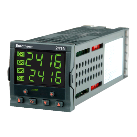
Eurotherm 2416 Manuals
Manuals and User Guides for Eurotherm 2416. We have
1
Eurotherm 2416 manual available for free PDF download: Installation And Operation Handbook
Eurotherm 2416 Installation And Operation Handbook (110 pages)
PID Controller
Brand:
Eurotherm
| Category:
Controller
| Size: 1 MB
Table of Contents
Table of Contents
3
Chapter 1 INSTALLATION
5
Mechanical Installation
6
Controller Labels
6
Outline Dimensions
6
Panel Cut-Out and Recommended Minimum Spacing of Controllers
7
To Install the Controller
7
Unplugging and Plugging-In the Controller
7
Electrical Installation
8
Rear Terminal Layout
8
Fixed Connections
9
Plug-In Module Connections
10
Communications Module
11
Wiring of 2-Wire EIA-485 Serial Communications Link
12
Typical Wiring Diagram
13
Logic Drive Fan out
14
Otorised Valve Connections
15
Chapter 2 OPERATION
17
Front Panel Layout
18
Basic Operation
20
Alarms
20
Operating Modes
21
Automatic Mode
22
Manual Mode
23
Parameters and How to Access Them
24
List Header Displays
24
Parameter Names
25
Parameter Displays
25
To Change the Value of a Parameter
25
Navigation Diagram (Part A)
26
Parameter Tables
28
Alarms
32
Alarm Annunciation
32
Alarm Acknowledgement and Resetting
32
Alarm Modes
32
Alarm Types
32
Process Alarms
32
Diagnostic Alarms
33
Chapter 3 ACCESS LEVELS
35
Edit Level
38
Chapter 4 TUNING
39
What Is Tuning
39
Automatic Tuning
40
Typical Automatic Tuning Cycle
41
Manual Tuning
42
Setting the Cutback Values
43
Integral Action and Manual Reset
44
Automatic Droop Compensation (Adc)
44
Tune Error
44
Motorised Valve Control
45
Commissioning the Motorised Valve Controller
46
Adjusting the Minimum On-Time 'Mp.t
46
Inertia and Backlash Settings
46
Gain Scheduling
47
Chapter 5 PROGRAMMER OPERATION
49
Chapter 6 CONFIGURATION
63
Selecting Configuration Level
64
Password Entry
64
Selecting a Configuration Parameter
65
Parameter Names
65
Changing the Passwords
65
Leaving Configuration Level
65
Navigation Diagram (PART A)
66
Configuration PARAMETER Tables
68
Chapter 7 User Calibration
79
WHAT IS the Purpose of User Calibration
79
User Calibration Enable
80
Offset Calibration
81
Two-Point Calibration
83
Calibration Points and Calibration Offsets
86
Chapter 8 LOAD CURRENT MONITORING and DIAGNOSTICS
87
Example Wiring Diagram (for Mode 1 & 2 Operation)
88
Operation
89
To Read Load Current (Mode 2 Only)
89
To Display Load Current Continuously in the Lower Readout (Mode 2 Only)
89
Display Modes
89
How Heater Alarms Are Displayed
90
To Set the Alarm Trip Levels
91
Short Circuit SSR Alarm and Heater Fail Alarm
91
Relay Outputs
91
To Configure Pds Load Current Diagnostics
92
To Configure the Logic Module for PDS Modes 1 or 2
92
To Configure Low and High Current Trip Alarms
94
To Attach Soft Alarms to a Relay Output
95
8.10 the Scaling Factor
96
To Adjust the Scaling Factor
96
Appendix Aunderstanding the ORDERING CODE
97
Appendix Bsafety and EMC INFORMATION
101
Appendix Ctechnical SPECIFICATION
105
Appendix D Rohs STATEMENT
107
Advertisement
Advertisement
Related Products
Eurotherm Invensys 2408
Eurotherm Invensys 2404
Eurotherm 2704
Eurotherm 2604
Eurotherm 2500
Eurotherm 2408i
Eurotherm 2132i
Eurotherm 2208e
Eurotherm 2208L
Eurotherm 2216e
Eurotherm Categories
Controller
Temperature Controller
Voice Recorder
Measuring Instruments
DC Drives
More Eurotherm Manuals
Login
Sign In
OR
Sign in with Facebook
Sign in with Google
Upload manual
Upload from disk
Upload from URL