Table of Contents
Advertisement
Advertisement
Table of Contents

Related Manuals for DAITEM SH146AX


Summary of Contents for DAITEM SH146AX
- Page 1 Updated for e-Nova applications...
-
Page 2: Table Of Contents
2.1 Opening • Operating differences with respect to former ranges are described in the compatibility booklet available the detector....73 in the Daitem Installers section at www.daitem.co.uk. 2.2 Description....73 2.3 Power supply ..... 74 The 12 m external motion detector with... -
Page 3: Preparation
Back box screwdriver and remove the cover. Cover 3. Guarantee sticker: remove the pre-cut part of the sticker and SH146AX stick it to the guarantee certificate in the user manual supplied Coller sur certif A1142A047879 with the control panel. If you are adding to an existing system,... -
Page 4: Power Supply
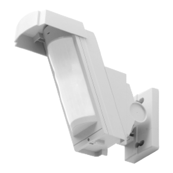
2.3 Power supply Detection module Cover (front view) Connecting the battery. Set of upper Detection circuit connector detection beams Angle adjustment Set of lower Operating option bracket detection beams dip switches Anti-mask selection dip switch Detection module (rear view) Sheet of adhesive masking strips Test button Programming When the detector is switched on, the... -
Page 5: Recognition Programming
3. Recognition programming 2. Proceed as follows to programme the detector to be recognised by the control panel. IMPORTANT: the device does not need to be placed close to the control panel for recognition programming. In fact, we advise “beep, detector X, “group?”... -
Page 6: Parameter-Setting
4. Parameter-setting The motion detector is factory- Parameter-setting Parameter n° Alarm level Parameter value configured for a deterrence (see sequence Intrusion your control panel installation Prealarm guide for system responses). The Deterrence 3 (factory setting) alarm level can be changed by Warning 4 (the feature is available using control panels with 2.0.0 version software or later) -
Page 7: Installation Precautions
5. Installation precautions 6. Installing the detector Before fixing the detector in place: IMPORTANT: make sure each product is at least two metres away from other devices, except other detectors. 1. Define the fixing height (2.5 to 3 m). 2. Determine the detection zone. The detector must be placed: perpendicular •... -
Page 8: Fixing The Detector In Place
6.1 Fixing the detector in place Fixing it flat against the wall Fixing the angle adjustment bracket The detector can be fixed to the wall without The bracket makes it possible to adjust the horizontal angle by approximately 90 degrees. the bracket if it does not need any horizontal If the ground is uneven and therefore not parallel to the base of the unit, the bracket allows or vertical adjustments. - Page 9 3. Loosen the adjustment 4. Decide which way round to fix the bracket depending on 5. Prepare the 3 blanks on the back screws so as to be able to the required detector angle. Then fix the angle adjustment box. rotate the axle.
-
Page 10: Setting The Detection Range
6.2 Setting the detection range 1. Install the detector at a height of 2.5 2. Apply the masking strips to the lens to adjust the detection distance. To set a distance to 3 m. The lower edge of the detector below the standard 12 m, choose one of the three shapes and apply it to the lens. -
Page 11: Setting The Vertical Angle
6.3 Setting the vertical angle 1. IMPORTANT: to ensure proper detector performance, set the vertical angle so that the base of the product is parallel to the ground. 2. Determine the required detection distance and mask the lens using the appropriate strips. 3. -
Page 12: Operating Options
7. Operating options Dip switches Detector in test mode The LED lights up when something is detected whatever the position of dip switch 6. 1 2 3 4 5 6 Detector in normal user mode (factory setting) Normal operating mode The LED is not lit when dip switch 6 is in OFF position. -
Page 13: Testing Operation
8.1 Testing the detection zone 8.2 Performing a real test 1. Mount the detection module and the lens on the back box. 1. Put the control panel in user mode by entering: installer code 2. Put the control panel in Total Arm mode. 3. -
Page 14: Maintenance
• The lithium battery pack must be replaced by the same type of pack with the same technical characteristics, i.e. (3.6 V - 4 Ah). • We advise you to use the DAITEM BatLi05 pack available in the catalogue in order to guarantee individual safety and equipment reliability. -
Page 15: Technical Data
Address: F-38926 Crolles Cedex - France Product type: Exterior 12 m motion detector with anti-mask function Anti-tamper protection against opening Trade mark: Daitem We declare under our sole responsibility that the product to which this declaration Anti-mask function 24-hour protection relates is compliant with the essential requirements of the following directives: •...
Need help?
Do you have a question about the SH146AX and is the answer not in the manual?
Questions and answers