Table of Contents
Advertisement
Quick Links
Before commencing assembly, please read these instructions thoroughly.
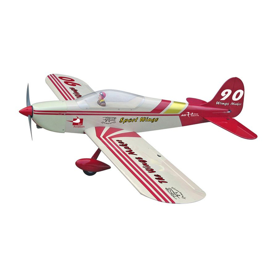
Wing Span: 81 in / 2050mm
Wing Area: 1020 sq in / 65.8 sq dm
Flying Weight: 9 lbs / 4100 g
Fuselage Length: 61 in / 1560mm
Radio required: 4 - stroke 0.91 engine
Warning ! This model is not a toy.
It is designed for maximum performance. Please seek advice if one is not familiar with this kind
of engine powered precision model. Operating this model without prior preparation may cause
injuries. Remember, safety is the most important thing. Always keep this instruction manual at
hand for quick reference.
* Specifications are subject to change without notice.*
THE WINGS MAKER
FACTORY PRE-FABRICATED
ALMOST-READY-TO-FLY (ARF) SERIES
MADE IN CHINA
www.thewingsmaker. com
Specifications
Specifications
4 - channel radio w/ 5 servos
INSTRUCTION MANUAL
GA011
Advertisement
Table of Contents

Related Manuals for The World Models Manufacturing SPORT WINGS 90


Summary of Contents for The World Models Manufacturing SPORT WINGS 90
- Page 1 INSTRUCTION MANUAL Before commencing assembly, please read these instructions thoroughly. Specifications Specifications Wing Span: 81 in / 2050mm Wing Area: 1020 sq in / 65.8 sq dm Flying Weight: 9 lbs / 4100 g Fuselage Length: 61 in / 1560mm Radio required: 4 - stroke 0.91 engine 4 - channel radio w/ 5 servos Warning ! This model is not a toy.
-
Page 2: Before You Begin
I N D E X BEFORE YOU BEGIN P. 1 PARTS LIST P. 2 ASSEMBLY P. 3 -9 SAFETY PRECAUTIONS P. 10 BEFORE YOU BEGIN Apply instant glue Apply epoxy glue. (C.A.glue, super glue.) Assemble left and right Ensure smooth non-binding sides the same way. -
Page 3: Parts List
Parts List 1. MAIN WING -- 1 pair 12. COWLING -- 1 set TRANSPARENT DUMMY COWLING -- 1 set 2. SCREW PM2 X 20mm -- 2 pcs PWA2.6 X 12mm -- 5 pcs SCREW PM2 X 25mm -- 4 pcs SILICON GROMMET d1.5 X D6.5mm -- 5 pcs PUSHROD Ø1.8 x 106mm w/ Threads (For Aileron) -- 2 pcs SPINNER Ø70mm -- 1 set... -
Page 4: Aileron Servo
Main Wing Pre-glued Bottom View Aileron Servo Ø1mm pilot holes for The Wings Maker tri-horn are pre-drilled. PM2 x 20mm Screw Please look for pin-hole marks at under side of control surfaces. PM2 x 25mm Screw straper 1.5mm PM2x25mm PM2x25mm Fuel Tube Ø6x5mm Clevis... - Page 5 Main Landing Gear PA 3 x 12mm Screw 3mm Set Screw Bottom View 5.1mm Collar Completed 3mm Set Screw Ø5.1mm Collar PA3 x 12mm Wheel Ø90mm Main Wing Wing Tuber Ø18 x 701mm Bottom View Stabilizer Elevator Apply thread locker to screws. d3 x D7mm Washer Pre-glued PM3 x 25mm Screw...
- Page 6 Vertical Fin Rudder Pre-glued C=C' Completed Tail Landing Gear PA 3 x 12mm Screw 3mm Set Screw WHEEL Ø25mm PA3 x 12mm 2.1mm Wheel Collar 2.1mm Wheel Collar PM2 x 14mm Screw 3 x 3mm Set Screw d2 x D5mm Washer PM2 x 14mm M2 Nut d2 x D5mm Washer...
-
Page 7: Engine Mount
Engine Mount M6 x 30mm Socket Head Screw M6 x 30mm Socket Head Screw d6 x D15mm Washer d6 x D15mm Washer Engine Mount Pl5911120 Apply thread locker to screws Blind nuts are off-centered to keep the spinner at the fuselage axis. Engine M4x35mm SOCKET HEAD SCREW Install Engine Position... -
Page 8: Rudder Pullwire
Cowling First insert the grommet to the cowling then apply screw. PWA2.6 x 12mm Screw d1.5 x D6.5mm Silicon Grommet Spinner d1.5 x D6.5 mm Silicon Grommet PWA2.6 x 12mm Rudder Pullwire Ø1mm pilot holes for The Wings Marker tri-horn are pre-drilled. Please look for pin-hole marks at side of control surfaces. -
Page 9: Radio Equipment
Servo Set LINKAGE CONNECTOR 3 x 3mm Set Screw Linkage Connector Included with the Radio Set. Throttle Rod 2mm Nut 2mm Washer Throttle Servo. Please refer to attached sheet for linkage connector installation. Radio Equipment Install and arrange the servo Copper Tube Press down the center as shown in the diagram. - Page 10 Canopy First insert the grommet to the canopy then apply screw. PWA2.3 x 8mm Screw Front Pilot d1.5 x D6.5mm Silicon Grommet PWA2.3 x 8mm d1.5xD6.5mm Silicon Grommet Main Wing PM4 x35mm Screw Front d4xD15mm Washer PM4x35mm d4xD15mm Washer Bottom View Completed P.
-
Page 11: Control Throws
Wing Setting Adjust the wing and fuselage configuration as shown in the diagrams. A = A ' B = B ' C = C ' Control Throws Adjust the control throws as shown in the diagram. These throws are good for general flying. - Page 12 www. thewingsmaker. com The ideal C.G. Position is 108mm (4.25 in) behind the leading edge measured at where the wing meets the fuselage. In order to obtain the C.G. specified, add weight to the fuselage or move the battery position. Check the C.G. before flying. 108mm 4.25 in.
Need help?
Do you have a question about the SPORT WINGS 90 and is the answer not in the manual?
Questions and answers