Table of Contents
Advertisement
Advertisement
Table of Contents

Related Manuals for Thermia Mega


Summary of Contents for Thermia Mega
- Page 1 User Guide Mega www.thermia.com...
- Page 2 The English language is used for the original instructions. Other languages are a translation of the original instructions. (Directive 2006/42/EC) © Copyright Thermia Värmepumpar...
-
Page 3: Table Of Contents
User Guide Mega Table of Contents Foreword .......... -
Page 4: Foreword
We thank you for the confidence that you have shown in us by buying a heat pump from Thermia . We hope that you will benefit from it for many, many years to come. -
Page 5: Safety Precautions
User Guide Mega Safety precautions Symbols in documents The instructions contain different warning symbols, which, together with text, indicate to the user that there are risks involved with actions to be taken. The symbols are displayed to the left of the text and three different symbols are used to indicate the degree of... -
Page 6: Installation And Maintenance
User Guide Mega This appliance can be used by children aged 8 Warning years and above, and by persons with reduced physical, sensory or mental capabilities or lack of experience or knowledge, provided that they are supervised or have been instructed in the safe use of the appliance and understand the hazards involved. -
Page 7: System Modifications
User Guide Mega System modifications Only qualified installers may carry out modifications on the following components: ▪ The heat pump unit ▪ The pipes for the refrigerant, brine and water ▪ The power supply ▪ The safety valves It is not permitted to carry out construction installations that may affect the operational safety of the heat pump. -
Page 8: About Your Heat Pump
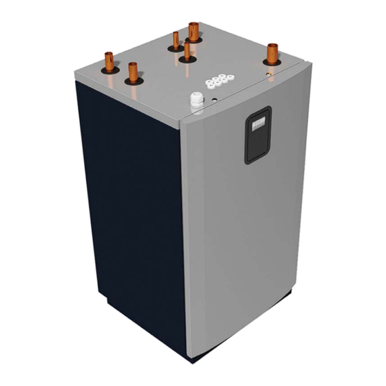
About your heat pump Product description The Mega heat pump is a heating system for heating and, if an external water heater is installed (accessory), for hot water production. It has a compressor which is customised for heat pumps. The Mega heat pump is equipped with control equipment which is presented in a graphic display. The control equipment is also prepared for monitoring via the internet. -
Page 9: Control System
User Guide Mega Control system The heat pump has an integrated control system which automatically calculates the heat demand in the build- ing to ensure that the correct amount of heat is produced and emitted when necessary. A touch screen is connected to the control system. - Page 10 User Guide Mega Drop down view There is a quick link to system information. Press at the top of any screen . 11:20 This screen appears where system information is presented. 11:20 /07/2015 13:15 5˚C Press at the bottom of the drop down view to hide the screen.
-
Page 11: Settings And Adjustments
User Guide Mega Settings and adjustments A qualified installer sets the heat pump's basic settings upon installation. The adjustments that may be made by the installer/user are described below. Never change control unit settings unless you are aware of what effects the changes may have. -
Page 12: Adjusting The Heat Curve
User Guide Mega Comfort adjustment, to change temperature Comfort adjustment means moving the whole curve upwards or downwards. Drag clockwise or anticlockwise to raise or lower the offset. Each point represents an increase/decrease of approximately 1°C on the supply line temperature. -
Page 13: Heating Settings
User Guide Mega Heating Settings In Heating settings, you can set seasonal stop and min/max supply line temperature. Default value is 1x. 1. Press on the Start screen to open the Menu screen. 2. Press 3. Press if the Heat settings window is not shown. - Page 14 User Guide Mega Set the heat pump to the desired operating mode in the menu: 1. Press on the Start screen to open the Menu screen. 2. Press . A new window opens. 3. Press the appropriate symbol for the desired operating mode.
- Page 15 User Guide Mega Symbol Description Operating mode Auxiliary heater + service. External functions are on. Auxiliary heater enabled and activated. In this mode the heat pump (compressor) is disabled, but the unit can produce heating and hot water with the internal im- mersion heater (and/or external auxiliary heater if activated).
- Page 16 User Guide Mega Symbol Description Operating mode Heat production. Space heating is permitted. Operating mode Hot tap water. Hot tap water production is permitted. VUJSC302 Thermia Värmepumpar...
-
Page 17: Distribution Circuits
User Guide Mega Distribution circuits Distribution circuit 1 is available from factory. Distribution circuits 2-5 require an expansion module, separately sold as accessory. Up to 5 distribution circuits can be active simultaneously. Example of settings for distribution circuit 1: 1. Press in the upper left corner of the Start screen 2. -
Page 18: System Information
User Guide Mega ▪ If the Curve indicator is lit, press to adjust the entire curve. ▪ Press and drag individual curve points: ▪ If the Curve indicator is not lit individual points can be moved separately by pressing to the desired temperature. - Page 19 User Guide Mega This information is useful when contacting support. Thermia Värmepumpar VUJSC302...
-
Page 20: Default Settings In The Control Unit
User Guide Mega Default settings in the control unit The left column in the table below shows the parameters that can be adjusted by the user. The middle column shows the factory settings. The right column shows the settings made by the installer when the heat pump was installed... -
Page 21: Regular Checks
User Guide Mega Regular checks Alarms If the display shows a green screen saver, the system is OK and no actions are required. There are three types of alarms: ▪ Class A: Stops the heat pump. The alarm must be acknowledged. -
Page 22: Checking The Brine Circuit Pressure
User Guide Mega Fig. 2: Alarm example Example of alarm messages: Message Meaning / Class Corrective action The heating circuit is the heat Check and, if necessary, rectify the level of the cir- High pressure pump's high pressure circuit. cuit. Acknowledge the alarm as described below. -
Page 23: Check The Water Level In The Heating Circuit
In case of doubt, contact your installer. NOTE: Do not use any additives for treatment of the water in the heating system, unless you have a written consent from Thermia! Checking safety valves The safety valves for the installation must be checked at least four times a year to prevent lime deposits clog- ging the mechanism. -
Page 24: In The Event Of Leakage
User Guide Mega In the event of leakage In the event of leakage in the hot water pipes between the heat pump and water taps, close the shut-off valve on the cold water inlet immediately. Then contact your installer. In the event of leakage in the brine circuit, turn off the heat pump and call your installer immediately. - Page 25 User Guide Mega Clean the filter as follows: 1. Switch off the heat pump. 2. For the brine circuit filter - remove the insulation around the filler cock. 3. Turn the shut-off tap (A) to the closed position. 4. Unscrew the cover (B) and remove it.
-
Page 26: Appendix
User Guide Mega Appendix Display symbol description Symbol Description Opens the menu screen from the start screen. Return to the menu screen from any sub-menu. Confirm setting. A change which has been made is confirmed and becomes the new setting. -
Page 27: Calculating Heat Production
User Guide Mega Symbol Description Push-pull control. Used for raising or lowering values. Press on the "handle" and push it to the sides. Alternatively, press Activation/deactivation of push-pull control or switch functions/equipment on/off. Press on the symbol to change mode. - Page 28 User Guide Mega The factory settings for the heat curve before adjustment is "40". This setting is suitable for many heating sys- tems with radiators, but generally unsuitable for systems with floor heating. For systems with underfloor heat- ing a standard heat curve setting is "30".
- Page 29 User Guide Mega Temperature (°C) Maximum setpoint value Outdoor temperature (°C) -2 0 If the curve is moved upwards, the heat curve will become steeper and if the curve is moved downwards, it will become flatter. The most energy efficient and cost effective setting is achieved by changing the curve settings which leads to fewer starts and longer operating times.
- Page 30 User Guide Mega Symbol description Fig. 1: The figure shows the standard curve 40 Symbol description Shows when the curve is comfort-adjusted. The digit shows how much. (+2) Shows that the comfort adjustment window is inactive. Press on the symbol to open comfort adjustment.
-
Page 31: Heating Settings
User Guide Mega Heating Settings For a temporary increase or reduction, adjust the Comfort setting instead. See Comfort settings in this appen- dix. Fig. 5: Heating Settings Seasonal stop Seasonal stop is at which outdoor temperature the heat pump will be blocked, or allowed, to produce heat. -
Page 32: Comfort Settings
User Guide Mega Comfort settings If you temporarily wish to increase or reduce the indoor temperature. Fig. 6: Comfort Settings When changing the comfort setting, the angle of the curve on the system's heat curve does not change, in- stead the entire heat curve is moved by 3°C for every degree change of the comfort setting. The reason that the curve is adjusted 3°C is that an approximate 3°C increase in supply temperature is usually needed to increase... -
Page 33: Checklist
User Guide Mega Checklist Location Surface adjustment Drainage Pipe installation, hot and cold side Pipe connections in accordance with the diagram Flexible hoses Expansion and bleed vessel Filter, hot and cold side Pipe insulation Open radiator valves Leak test, hot and cold side... -
Page 34: Installation Carried Out By
User Guide Mega Installation carried out by: Piping installation ▪ Date: ▪ Company: ▪ Name: ▪ Tel. No: Electrical Installation ▪ Date: ▪ Company: ▪ Name: ▪ Tel. No: System adjustment ▪ Date: ▪ Company: ▪ Name: ▪ Tel. No: VUJSC302 Thermia Värmepumpar... - Page 35 User Guide Mega Thermia Värmepumpar VUJSC302...
- Page 36 All trademarks in this material are property of the respective companies. Thermia Värmepumpar and the Thermia Värmepumpar logotype are trademarks of Danfoss A/S. All rights reserved.
Need help?
Do you have a question about the Mega and is the answer not in the manual?
Questions and answers