Table of Contents
Advertisement
Advertisement
Table of Contents

Related Manuals for Thermia Athena


Summary of Contents for Thermia Athena
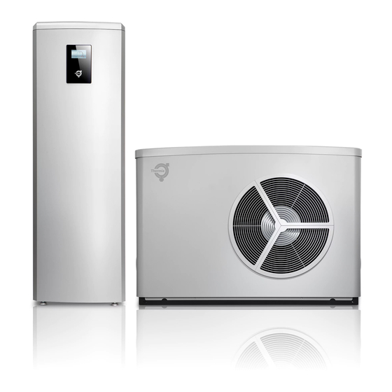
- Page 1 Installation Guide Athena www.thermia.com...
- Page 2 Thermia AB is not liable or bound by warranty if these instructions are not adhered to during installation or service. The English language is used for the original instructions. Other languages are a translation of the original instructions. (Directive 2006/42/EC)
-
Page 3: Table Of Contents
Athena outdoor electrical connections access ........ -
Page 4: About Documents And Decals
Installation Guide Athena About documents and decals Introduction The following documents are available for this product: ▪ The Installation Quick Guide is an illustrated step-by-step guide on how to install the heat pump. Supplied with the heat pump on delivery. -
Page 5: Symbols On Decals
Installation Guide Athena Symbols on decals The following symbols can occur on decals on the different parts of the heat pump. Which symbols are used depends on the heat pump model. 1.3.1 General Warning, danger! Read the documentation provided. Read the documentation provided. -
Page 6: Important Information/Safety Regulation
General safety precautions Carefully follow the precautions listed as below because they are essential to guarantee the safety of Thermia product. Store the manual in a safe place in order to be able to use it as reference after installation. Remember to hand it over to the new owner if the heat pump unit is sold or transferred. - Page 7 Installation Guide Athena The units contain moving parts and electrical parts, which should al- Warning ways be kept out of the reach of children. Do not touch the internal parts (water pipes, refrigerant pipes, heat ex- Warning changers, etc) while running the units. If you need to adjust and touch the units, have enough time for the unit to be cooled off and be sure to wear protective gloves.
- Page 8 The safety valve overflow pipes must have an open connection to the Caution drain and a visible flow into this in a frost-free environment. Do not start the unit ( Athena Total EQ, Athena Total 300L & Athena Caution Compact) if there is a possibility of frozen water in the immersion heater.
-
Page 9: Refrigerant
It is important that the entire system is vented for air after installation. When the Thermia air/water heat pump system is used in series with another heat source (e.g. gasboiler), ensure that the return water tem- perature does not exceed 60°C. - Page 10 Athena 2.2.2 Work on the refrigerant circuit All warranties from Thermia are void if, when filling with refrigerant Caution other than Thermia specified refrigerant, if there has not been written notification that the new refrigerant is an approved replacement re- frigerant together with other remedies.
-
Page 11: Heat Pump Data
2. Return line (push-fit connection, see chapter 7.3.1), Ø28mm 3. Back side/air intake 4. Front side/air discharge 5. Drain 6. Condensate drain, Ø25mm 7. Insert for stabilizing screws (M8x4) 8. Air venting 1380 * Athena HC is only available in certain markets. 1490 Thermia AB AWAT01IGCG0102... - Page 12 Installation Guide Athena 3.1.2 Indoor unit Indoor unit Athena Total 300L 1a. Hot water line, 22 mm 1b. Cold water line, 22 mm 2a. Heating system supply, 28 mm 2b. Heating system return, 28 mm 3. Connection for bleed valve, 28 mm 4a.
- Page 13 Installation Guide Athena Indoor unit Athena Compact 1a. Hot water line, 22 mm 1b. Cold water line, 22 mm 2a. Heating system supply, 28 mm 2b. Heating system return, 28 mm 3. Connection for bleed valve, 28 mm 4a. Supply line from outdoor unit, 28 mm Cu (left or right) 4b.
- Page 14 Installation Guide Athena Indoor unit Athena Total EQ 1a. Hot water line, 22 mm 1b. Cold water line, 22 mm 2a. Heating system supply, 28 mm 2b. Heating system return, 28 mm 3. Connection for bleed valve, 28 mm 4a. Supply line from outdoor unit, 28 mm Cu (left or right) 4b.
-
Page 15: Preparing For Installation
Installation Guide Athena Preparing for installation Preparing for the outdoor unit The outdoor and indoor unit shall be installed in compliance with the spaces described in the installation manual, to ensure accessibility from both sides and allow repairs or maintenance operations to be carried out. If the units installed without complying with procedures described in manual, additional expenses can be asked because special harnesses, ladders, scaffolding or any other elevation system for repair service will NOT be considered part of the warranty and will be charged to the end customer. - Page 16 Installation Guide Athena ≥800 ≥300 ≥500 ≥1000 ≥2000 ≥400 The appliance is intended to be in front of a wall, so if there is no wall where the unit is installed, one has to be constructed. The wall should be at least 250mm on each side of the outdoor unit to serve as proper wind protection, as shown in the picture.
- Page 17 Installation Guide Athena A. Depth of frost line 1. Heating flow 2. Heating return 3. Condensate drain conduit 4. Gravel bed 5. Concrete foundation 6. Box stand 7. Heating cable inside the drain pipe A. Depth of frost line B. 300mm C.
-
Page 18: Preparing For The Indoor Unit
(Athena Total EQ, Athena Total 300L & Athena Compact) The appliance shall be stored and installed so as to prevent mechanical damage from occurring. - Page 19 Installation Guide Athena 300 mm Athena Total EQ Athena Total 300L Athena Compact 300 mm 300 mm 30°C 10 mm +5°C 600 mm Adjust the heat pump using the adjustable feet and a spirit level. 13mm 16mm Thermia AB AWAT01IGCG0102...
-
Page 20: Transporting And Setting Up
Athena HC* 188 kg Athena H 176,5 kg * Athena HC is only available in certain markets. Moving the outdoor unit with a forklift ▪ Lift the outdoor unit carefully from the left side (facing the front) (3), due to the center of gravity (1). Be careful not to damage the outdoor unit. -
Page 21: Transporting And Setting Up The Indoor Unit
Installation Guide Athena Transporting and setting up the indoor unit During transportation and lifting of the indoor unit (Athena Total EQ, Caution Athena Compact, and Athena Total 300L), the front panel must always be in place as it locks the other panels in position. -
Page 22: Unpacking
Installation Guide Athena Athena Total EQ: 164 kg Athena Compact: 113 kg Athena Total 300L: 138,5 kg Unpacking 5.3.1 General information Wear protective gloves to unpack, move, install, and service the unit to Warning avoid your hands being injured, for instance by sharp edges. - Page 23 Installation Guide Athena For all deliveries: Magnetite filter For Athena Total EQ and Athena Compact: 1. Accessory box 2. Water pipe out 3. Water pipe in 4. Safety valve, 9 bar 5. Safety valve, 3 bar, 1/2" 6. Outdoor sensor 7.
-
Page 24: Noise Information
Installation Guide Athena Noise information 5.4.1 Consideration to prevent noise To prevent disturbing noise from the heat pump the following recommendations should be observed: ▪ In the event the heat pump is positioned on a vibration sensitive base, vibration dampers should be used. The vibration dampers must be correctly dimensioned with regard to the heat pump's weight so that static spring depression of at least 2 mm is obtained in all mounting components. -
Page 25: Installation Notes Regarding Refrigerant
Installation Guide Athena Installation notes regarding refrigerant Note that the refrigerant has no odour. Caution ▪ Do not cut, pierce, or burn the refrigerant container or pipes. ▪ Do not use means to accelerate the defrosting process for example with an open flame or other methods besides the heat pump´s defrosting program. -
Page 26: Piping Installation
If cooling function will be used, it is very important to insulate all pipes Caution from condensation. Applies only to Athena HC models. Athena HC is only available in certain markets. Heating systems with closed expansion tanks must also be supplied Caution with approved pressure gauges and safety valves. -
Page 27: Water Volume In The Heating System
°C +15 to +37 +12 to +37 * Applies only to Athena HC models. Athena HC is only available in certain markets. Checklist before installing Before installing the unit, make sure to check the following: ▪ The maximum water pressure of the unit is 2.8 bar static pressure. -
Page 28: Water Flow In The Heating System
Installation Guide Athena Water flow in the heating system The minimum flow rate and defrost energy must always be assured. The minimum flow rate is 1 m³/h and the recommended flow rate is to have at least a 10% margin, resulting in a recommended flow rate of 1,1 m³/h or approximately above 18 litres per minute. -
Page 29: Connection Heating And Hot Water
Installation Guide Athena Connection heating and hot water 6.4.1 Connecting the heating system supply and return lines to the outdoor unit 1. Supply line, push-fit connection, Ø28mm 2. Return line, push-fit connection, Ø28mm 3. Drain 4. Ventilation, plastic twist cap The water in- and outlet on the outdoor unit are factory fitted with push-fit connectors. - Page 30 Installation Guide Athena Water connections must be made in accordance with the outlook diagram delivered with the unit, respecting the water in- and outlet. If air, moisture or dust gets in the water circuit, problems may occur. Therefore, always take into account the following when connecting the water circuit: ▪...
-
Page 31: Water Quality
Installation Guide Athena 6.5.3 Filter / Strainer Installation of Filter / Strainer is mandatory for water system. The Filter or Strainer shall be located in front of inlet pipe of the plate heat exchanger. While operating the system, some dust and foreign materials can circulate the system and can make the whole system not work well due to blockage of heat exchangers and corrosion in some components. -
Page 32: Athena
Dirt strainer with shut-off valve, DN 25 Magnetite filter Expansion vessel (built-in for Athena Total EQ) Make sure that a free flow is always possible on the heating circuit. Very small water volumes or stop in the heating circuit may cause operational disturbances. -
Page 33: Connections To Outdoor Unit, Alternatives
Installation Guide Athena Connections to outdoor unit, alternatives 1. Left knock-out 2. Right knock-out Equipment set-up for installing Thermia AB AWAT01IGCG0102... -
Page 34: General Information For Connections To Outdoor Unit
Installation Guide Athena General information for connections to outdoor unit The quick couplings included are tool-free and pushed in place. The coupling locks automatically. Before mounting, check that there are no sharp edges or irregularities on the pipe that could damage the rubber sealing in the couplings and cause leakage. The coupling can be rotated after being mounted. - Page 35 Installation Guide Athena Be careful not to damage the electrical wiring attached to the display Caution when the front cover is removed! 1. Press against the front cover and turn the catch 90° degrees anti-clockwise to release the front cover.
-
Page 36: Alternative 1 (Left)
Installation Guide Athena 6.10 Alternative 1 (left) For connection in to the left hand side "knockout holes". 1, Press the quick couplings (delivered with the heat pump) on to the pipes according to the picture . Make sure the coupling reach the 32 mm mark. -
Page 37: Alternative 2 (Right)
Installation Guide Athena 6.11 Alternative 2 (right) For connection in to the right hand side "knockout holes". 1, Press the quick couplings (delivered with the heat pump) on to the pipes . Make sure 32 mm the coupling reach the 32 mm mark. -
Page 38: Electrical Installation
Installation Guide Athena Electrical Installation The heat pump is connected internally at the factory, for this reason electrical installation consists mainly of the connection of the power supply. Hazardous electrical voltage! The terminal blocks are live and can Danger cause death through electric shock. All power supplies must be isola- ted before electrical installation is started. - Page 39 Installation Guide Athena Be sure to install both an earth leakage detector and circuit breaker with specified capacity in accordance with relevant local and national regulations. If not installed properly, it may cause electric shocks and fire. Thermia AB AWAT01IGCG0102...
-
Page 40: Sensors And Power Supply
Also take into account the effects of aging or continual vibration from sources such as compressors or fans. The wiring shall be installed in accordance with national wiring regulations. Athena 400V outdoor unit complies with IEC 61000-3-12 without conditional connection. Make sure that all grommets are in place at the top of the indoor unit and the electri- cal cabinet, regardless of which ones are in use. -
Page 41: Outdoor Sensor
1. Improper placement 2. Proper placement Power supply 400V version 15mm L1 L2 L3 Athena Total EQ 400V, Athena Total 300L 400V & Athena Compact 400V ▪ L1: Control and circulation pump ▪ L1, L2, L3: Internal immersion heater Thermia AB AWAT01IGCG0102... -
Page 42: Fuse Sizes 400V
~3N, 50 Hz fuse C-curve Athena I max: 9,5A 13,5A Fuse: (6A) (10A) (16A) Built in immersion heater Step 1 Step 2 Step 3 3 kW 6 kW 9 kW Athena Total EQ, Athena Total 300L & Athena Compact AWAT01IGCG0102 Thermia AB... -
Page 43: Electrical Connections
Installation Guide Athena Electrical connections Athena outdoor electrical connections access Before working on the appliance, isolate it from the power supply The leakage current of this appliance can be >3.5mA If the heat pump is connected to ground fault switch RCDs, it should be connected to a separate type B. - Page 44 Installation Guide Athena After folding out the terminal section, pull out the plastic arm/detail on the top and secure it in the chassi to the left, according to the picture, to keep the termi- nal in place while working. Installing ribbon heater When installing on foundations or stands, if the routing of the condensate hose means there is at risk of frost or is fully exposed to the elements, we recommend installing a ribbon heater.
-
Page 45: Outdoor Terminal Connections
Installation Guide Athena Outdoor terminal connections Inputs for the outdoor unit according to the picture and table below 5V A B L1 L2 L3 L1 L2 L3 Electrical heater Compressor Control voltage 2,6 kW N PE 3,0 kW 3,2 kW... -
Page 46: Athena Electrical Connections 400V (This Label Is Also Fitted On The Electrical Cabinet Of The Heat Pump)
Installation Guide Athena Athena electrical connections 400V (this label is also fitted on the electrical cabinet of the heat pump) L1 L2 L3 N L N PE Outdoor unit connections Outdoor unit connections Overheat protection reset Outdoor unit UV-resistant twisted pair data/telephone, shielded, 0.75mm²... -
Page 47: Commissioning
▪ The access code is active for 8 hours. After 8 hours, logging out or restart, the code must be entered again. 10.2 Online The heat pump is factory prepared for monitoring remotely via internet. (Thermia Online) In order to use the Thermia Online service: ▪ Make sure that there is an available internet connection (router or equivalent) in the building ▪... -
Page 48: Selecting Hot Water Settings
3. Press the (crossed) Cooling symbol 4. In the Cooling menu, activate the cooling function. 5. Go back to the start menu and make sure that the Cooling icon is lit, * Athena HC is only available in certain markets. AWAT01IGCG0102 Thermia AB... -
Page 49: Display Symbol Description
Installation Guide Athena 10.6 Display symbol description Not all symbols are applicable in all installations. Symbol Description Opens the menu screen from the start screen. Return to the menu screen from any sub-menu. Confirm setting. A change which has been made is confirmed and becomes the new setting. - Page 50 Cooling mode. Visible in the top of the display when the heat pump is in cooling mode. Visible only for Athena HC models. Athena HC is only available in certain markets. Idle mode. Visible in the top of the display when the heat pump has no heating, cooling or hot water de- mand.
-
Page 51: Additional Functionality
Requires EM3:0 See EM3 manual External alarm Requires EM3:0 See EM3 manual * Cooling functionality is only for Athena HC models. Athena HC is only available in certain markets. 11.2 How to set up additional accessories, functions etc. For more detailed information and system solutions see separate instruction or system solution generator on the website. - Page 52 Installation Guide Athena 3. Go to SETTINGS menu again and select the function previously activated in installation menu and activate the function by pressing the switch. 4. Make desired settings and confirm. 5. Restart heat pump and check functionality. AWAT01IGCG0102...
-
Page 53: Check List
▪ The operating range of leaving water temperature is 20~65˚C at heating conditions and 12~37˚C at cooling* conditions. ▪ Do not operate the system with closed valves because it results in damaging the heat pump. * Cooling only applies to Athena HC models. Athena HC is only available in certain markets. Thermia AB... -
Page 54: Checking The Electrical Installation
Installation Guide Athena 12.2 Checking the electrical installation Before turning on electrical power, check the electrical installation according to the checklist below Electrical installation checklist Are circuit-breakers installed? One for indoor unit and one for outdoor unit (not included in the delivery) Are correct fuses installed? See fuse table. - Page 55 Installation Guide Athena Thermia AB AWAT01IGCG0102...
- Page 56 Internet: www.thermia.com Thermia can accept no responsibility for possible errors in catalogues, brochures and other printed material. Thermia reserves the right to alter its products without notice. This also applies to products already on order provided that such alterations can be made without subsequential changes being necessary in specifications already agreed. All trademarks in this material are property of the respective companies.
Need help?
Do you have a question about the Athena and is the answer not in the manual?
Questions and answers