flowair LEO FB 95 Operation Manual
Hide thumbs
Also See for LEO FB 95:
- Technical documentation operation manual (23 pages) ,
- Operation manual (29 pages) ,
- Operation manual (20 pages)

Subscribe to Our Youtube Channel
Related Manuals for flowair LEO FB 95


Summary of Contents for flowair LEO FB 95
- Page 1 TECHNICAL DOCUMENTATION OPERATION MANUAL DOKUMENTACJA TECHNICZNA INSTRUKCJA UŻYTKOWANIA TECHNISCHE DOKUMENTATION BETRIEBSANLEITUNG ТЕХНИЧЕСКАЯ ДОКУМЕНТАЦИЯ РУКОВОДСТВО ПОЛЬЗОВАТЕЛЯ...
- Page 3 5.2. Other Methods of Installation 5.2. Inne sposoby montażu 6. Automatic Systems 6. Automatyka 6.1. LEO FB 95 Automatic Elements 6.1. Elementy automatyki LEO FB 95 6.2. LEO FB 95S Control 6.2. Sterowanie LEO FB 95S RA and Fans Connection Podłączenie RA oraz wentylatorów...
- Page 4 5.2. Другие способы установки 6. Steuerung 6. Автоматика 6.1. Zubehör für LEO FB 95 6.1. Составные элементы системы управления LEO FB 95 6.2. Steuerung LEO FB 95S 6.2. Управление LEO FB 95S Anschluss von RA und der Ventilatore Подключение RA и вентиляторов...
- Page 5 Thank you for purchasing the LEO FB 95 water heater. Dziękujemy Państwu za zakup nagrzewnicy wodnej LEO FB 95. This operation manual has been issued by the FLOWAIR GŁOGOWSKI I BRZEZIŃSKI SP.J. Niniejsza instrukcja obsługi została wydana przez firmę FLOWAIR GŁOGOWSKI...
- Page 6 Get acquainted with this operation manual before performing any works at the device. Przed wykonaniem jakichkolwiek prac przy urządzeniu należy zapoznać się z niniejszą The device may only be installed by qualified personnel possessing adequate instrukcją obsługi. authorisations and skills. Urządzenie może być...
- Page 7 LEO FB 95, przy jednoczesnym zachowaniu stosunkowo niedużych gabarytów. The LEO FB 95 device filled with water weights 38kg, has rated heating capacity 100,1 kW and may be executed in one of two varieties (types): Urządzenie LEO FB 95 napełnione wodą...
- Page 8 Analiza różnego rodzaju rozwiązań, próby, konsultacje z konstruktorami the device, which is both very aesthetic and functional. High quality of LEO FB 95 pozwoliły na uzyskanie urządzenia, które posiada wysokie walory estetyczne oraz heaters is secured by latest technologies, used to their production, and application of funkcjonalność.
- Page 9 Kupfer-Anschlüssen mit dem Außengewinde ¾”, die darüber hinaus speziell für den ламели оптимальных форм и размеров. Теплообменник оснащен медными патрубками Maulschlüssel 27 geformt sind, was die Installation erleichtert. Der Lufterhitzer LEO FB 95 ist mit einem zweireihigen Heizregister ausgestattet. Die maximalen Betriebsparameter des с...
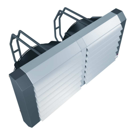
- Page 10 1. Mounting bracket* 1. Konsola montażowa* 2. Fan 2. Wentylator 3. Air nozzle 3. Dysza kierunkowa 4. Heat exchanger 4. Wymiennik ciepła 5. Air guides 5. Kierownice powietrza 6. Casing 6. Obudowa *The mounting brackets do not constitute a *Konsole montażowe stanowią...
- Page 11 V – airflow V – przepływ powietrza V – Luftdurchfluss V – объем воздуха PT – heat capacity PT – moc grzewcza PT – Heizleistung PT – мощность нагрева Tp1 – inlet air temp. Tp1 – temperatura powietrza na Tp1 – Lufteintrittstemperatur Tp1 –...
- Page 12 (using special lub 45 (możliwe po zastosowaniu mounting brackets*) specjalnych konsol*) As standard, LEO FB 95 water heater is Nagrzewnica wodna LEO FB 95 standardowo executed with hydraulic connection on the right wykonana jest z podejściem hydraulicznym side (looking from the back of the device).
- Page 13 (возможно Montagekonsolen möglich*) при применении монтажных консоль*) В стандартном варианте отопительный аппарат Wasserlufterhitzer sind LEO FB 95 может крепиться к гидравлическим standardmäßig mit dem Vorlauf an der rechten патрубкам с правой стороны (вид сзади Seite ausgeführt (von hinten gesehen). Die аппарата).
- Page 14 LEO FB 95 heaters are equipped in guides LEO FB 95 posiada kierownice powietrza, które (blades), which can be put in vertical or można zamontować pionowo lub poziomo w oknie horizontal position in heater window. This nagrzewnicy. Dzięki temu można w łatwy sposób, solution makes it easier to aim the air flow in demontażu...
- Page 15 Special mounting brackets have been Do zamontowania nagrzewnicy zostały designed for installation of the heater. specjalnie zaprojektowane konsole They make it possible to suspend the montażowe, które umożliwiają device on both vertical and horizontal zawieszenie urządzenia na przegrodach partitions of the building. The mounting pionowych jak i poziomych.
- Page 16 In the partition fasten 8 expansion bolts W przegrodzie utwierdzić 8 kołków together with installation pins , in spacing rozporowych wraz szpilkami corresponding to the spacing of the holes in montażowymi w odstępach the mounting brackets. odpowiadających rozstawom otworów w konsolach. Remove 4 screws fastening the nozzles Wykręcić...
- Page 17 In the case of independent preparation of the installation przypadku samodzielnego przygotowania ramy frame, the threaded holes designed for connecting with the montażowej należy, do jej połączenia z urządzeniem, original mounting brackets (M10 thread) should be used for wykorzystać otwory gwintowane przeznaczone connecting the frame to the device.
- Page 18 LEO FB 95S i LEO FB 95M. Die Lufterhitzer LEO FB 95 sind für den Betrieb das Ventilators mit 2 grundlegenden Для аппаратов LEO FB 95 возможны два основных типа управления работой Steuerungen ausgestattet: вентилятора:...
- Page 19 Automatic elements do not constitute a standard equipment of the heaters. They are available as an Elementy automatyki nie stanowią standardowego wyposażenia nagrzewnic. Występują extra equipment. jako wyposażenie dodatkowe. Bestandteile des Zubehörssind keine standardmäßigen Ausrüstungen. Sie sind als optional Элементы системы управления не входят в состав стандартного оснащения erhältlich.
- Page 20 3A five step fan speed regulator 5-stopniowy regulator obrotów 5-Stufenschalter 3A Пятиступенчатый регулятор o maksymalnej obciążalności 3A скорости вращения Supply voltage: 230V 50/60Hz Versorgungsspannung: вентилятора - 3,0А Protection degree: IP54 Napięcie zasilania: 230V 230V 50/60Hz Operation temp. range: 50/60Hz Schutzklasse: IP54 Напряж.
- Page 21 3/4" three-way valve with Zawór trójdrogowy 3/4" 3-Wege-Regelventil mit Трехходовой клапан 3/4" с сервоприводом actuator z siłownikiem Stellmotor, Außengewinde 3/4" Степень защиты: IP40 Protection degree: IP40 Stopień ochrony: IP40 Напряжение питания: Supply voltage: Napięcie zasilania: Schutzklasse: IP40 200 – 240В 50/60Гц Versorgungsspannung: Макс.
- Page 22 Programmable fan speed Programowalny nastawnik Steuerpanel mit integriertem Командоконтроллер вентилятора с встроенным controller with a built-in room obrotów z wbudowanym Drehzahlsteller, thermostat termostatem Raumthermostat und комнатным термостатом и недельным таймером Wochenprogrammuhr Supply voltage: Napięcie zasilania: 230V Versorgungsspannung: Напряжение питания: 230В 230V 50Hz 50Hz Output control signal:...
- Page 23 Внешний датчик Wall-mounted temperature Czujnik naścienny Wandtemperaturfühler sensor pomiaru temperatury температуры Степень защиты: IP65 Protection degree: IP65 Stopień ochrony: IP65 Schutzklasse: IP65 Operation temperature Zakres temperatury Bereich der Диапазон рабочей температуры: range: pracy: Betriebstemperatur: -50 … +110 -50 … +110 -50 …...
- Page 24 The heater operation is controlled by the RA Pracą nagrzewnicy steruje termostat room thermostat through stopping and starting pomieszczeniowy poprzez the fan motors. Heating water parameters are zatrzymywanie i uruchamianie silników controlled by the boiler automatic system. wentylatorów. Parametry wody grzewczej kontrolowane są...
- Page 25 System with RA or RD room thermostat and SRV2d Układ z termostatem pomieszczeniowym RA lub valve with actuator. The thermostat controls the oraz zaworem z siłownikiem SRV2d. valve operation, opening or closing the heating Termostat steruje pracą zaworu zamykając lub medium supply.
- Page 26 Control system consisting of RA or RD room thermostat, SRV2d Układ sterowania, który tworzą termostat pomieszczeniowy RA valve with actuator and TRd fans speed regulator. This system lub RD, zawór z siłownikiem SRV2d oraz regulator obrotów allows regulation of heating medium flow (ON/OFF) with a wentylatorów TRd.
- Page 27 System with room thermostat RA and a valve with Układ z termostatem pomieszczeniowym RA oraz servo SRV3d. Thermostat controls the valve. zaworem z siłownikiem SRV3d. Termostat steruje Heating medium is directed either to the heater or pracą zaworu. Czynnik grzewczy kierowany jest do to the return loop (pipe) of the heat exchanger.
- Page 28 System with room thermostat RA, a valve with servo Układ sterowania, który tworzą termostat pomieszczeniowy SRV3d and fans speed regulator TRd. Thermostat RA, zawór z siłownikiem SRV3d oraz regulator obrotów controls the servo-valve. Heating medium is directed wentylatorów TRd. Termostat steruje pracą zaworu. either to the heater or to the return loop (pipe) of the heat Czynnik grzewczy kierowany jest do nagrzewnicy bądź...
- Page 29 SW3 – operation mode switch SW3 – przełącznik tryby pracy AUTO/MANUAL (1-manual operation mode, AUTO/MANUAL 2- auto operation mode). (1-tryb pracy manual, 2-tryb pracy auto). Default setting: 1 Fabryczna nastawa: 1 SW2 – temperature sensor selection SW2 – wybór czujnika temperatury (1-czujnik (1-internal sensor, 2-external sensor).
- Page 30 Control component elements are VNT20 fan speed controller and optionally SRV2d or SRV3d valve with Elementy składowe sterowania to nastawnik obrotów VNT20 oraz opcjonalnie zawór z siłownikiem actuator and PT-1000 IP20 or PT-1000 IP65. SRV2d lub SRV3d oraz zewnętrzny czujnik PT-1000 IP20 lub PT-1000 IP65. fan junction box located outside on the cable puszka podłączeniowa wentylatora wyprowadzona na kablu (power connection with OMY 3x1mm...
- Page 31 VNT20 connection diagram | Schemat podłączenia VNT20...
- Page 32 Составные элементы системы это командоконтроллер вентилятора VNT20, а также опционально клапан Diese Steuerungsanlage bilden das Steuerpanel VNT20 und optional das Regelventil mit Stellmotor SRV2d с сервоприводом SRV2d или SRV3d и внешний датчик температуры PT-1000 IP20 или PT-1000 IP65. oderSRV3d wie auch der externe Temperaturfühler PT-1000 IP20 oder PT-1000 IP65. присоединительная...
- Page 33 Anschlussschema VNT20 | Схема соединения VNT20...
- Page 34 Control component elements are VNTLCD a programmable fan speed controller with a built-in Elementy składowe sterowania to programowalny nastawnik obrotów z wbudowanym room thermostat and optionally SRV2d or SRV3d valve with actuator and PT-1000 external termostatem VNTLCD oraz opcjonalnie zawór z siłownikiem SRV2d lub SRV3d oraz sensor.
- Page 35 VNTLCD connection diagram | Schemat podłączenia VNTLCD...
- Page 36 Diese Steuerungsanlage bilden das Steuerpanel mit dem Display VNTLCD und optional das Составные элементы системы это командоконтроллер вентилятора с встроенным комнатным термостатом и недельным таймером VNTLCD, а также опционально клапан Regelventil mit Stellmotor SRV2d oder SRV3d und der Temperaturfühler PT-1000. с...
- Page 37 Anschlussschema VNTLCD| Схема соединения VNTLCD...
- Page 38 1 or 4 PT-1000 sensors may be nastawników VNT20 oraz connected simultaneously VNTLCD można podłączyć controllers VNT20 and VNTLCD. równocześnie 1 lub 4 czujniki PT- 1000. Connection diagram for 4 sensors is presented in the figure. Schemat podłączenia 4 czujników został...
- Page 39 Przyłącze powinno być wykonane w sposób nie powodujący naprężeń. The connection should be executed in a way which does not cause stresses. Zalecane jest zastosowanie zaworów odpowietrzających w najwyższym punkcie It is recommended to use vent valves at the highest point of the system. instalacji.
- Page 40 Before connecting the power supply check the correctness of connection of the fan’s Przed podłączeniem zasilania należy sprawdzić poprawność podłączenia silników motors and the controllers. These connections should be executed in accordance with wentylatorów i nastawników. Podłączenia te powinny być wykonane zgodnie z ich their technical documentation dokumentacją...
- Page 41 The device is designed for operation inside buildings, at temperatures above 0 C. In low Urządzenie przeznaczone jest do pracy wewnątrz budynku, w temperaturach powyżej 0 C. W niskich temperatures (below 0ºC) there is a danger of freezing of the medium. temperaturach (poniżej 0ºC) istnieje niebezpieczeństwo zamarznięcia czynnika.
- Page 42 117036, г. Москва ● ул. Дмитрия Ульянова, д.19 ● Тел: +7 495 6425046 ● Тел/факс: +7 495 7950063 ● e-mail: info@flowair.ru ● www.flowair.ru ● FLOWAIR UKRAINE LTD ● Эксклюзивный дистрибьютор в Украине ● 83014, г.Донецк ● проспект Дзержинского, дом16 ●...
- Page 44 LEO FB 95/1.0/09.09/ENPLDERU...
Need help?
Do you have a question about the LEO FB 95 and is the answer not in the manual?
Questions and answers