
Related Manuals for lavina 25-X


Summary of Contents for lavina 25-X
- Page 1 LAVINA 25-X User Manual ® Tech Support Line: 800-987-8403 | www.superabrasive.com | info@superabrasive.us ...
- Page 2 Superabrasive User Manual Original Language Lavina® 25‐X 3/2015 2 ...
-
Page 3: Warranty And Returns
The warranty herein is non-transferable, and only applies to the original owner or purchaser of the machine. RETURN POLICY FOR LAVINA® X MACHINES The LAVINA® X machines may be returned, subject to the following terms: In no case, a machine is to be returned to Superabrasive Inc. for credit or repair without prior authorization. -
Page 4: Table Of Contents
VIBRATIONS .................. 6 ELECTRICAL SYSTEM ................ 1 3 SONOROUS EMISSIONS ................ 6 LAVINA® 25‐X ELECTRICAL SCHEMES WITH YASKAWA INVERTER .. 1 4 LABEL DATA................... 6 LAVINA® 25‐X ELECTRICAL SCHEMES YASKAWA CONNECTION MAIN CUSTOMER SERVICE ................ 6 CIRCUIT TERMINALS ................ 1 4 2. SAFETY INSTRUCTIONS .............. 6 8. TROUBLESHOOTING ................. 1 5 ... -
Page 5: General Information
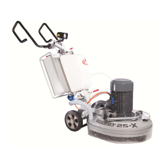
User Manual Original Language Lavina® 25‐X 3/2015 1. GENERAL INFORMATION This owner’s manual is intended for the operator of the Lavina® X machine, the servicing technician as well as for anyone involved with operating or servicing the machine. We recommend that you read the instructions very carefully and follow them strictly.The manual includes information about assembling, using, handling, adjusting and maintaining your Lavina® X floor grinding andpolishing machine. MANUFACTURER Superabrasive was founded in 1987, as a manufacturer of high quality diamond tools for the stone and concrete industry. Today, Superabrasive is one of the world’s leading companies in the production of diamond tools and floor grinding machinery. At Superabrasive, we strive to deliver the very best solutions to our customers, and enable them to work more efficiently. GENERAL DESCRIPTION The Lavina® X machine is intended for grinding, polishing and buffing concrete, marble, granite, limestone, and terrazzo surfaces with diamond tools. The Lavina® X machine is a three‐disc machine, which can be used dry as well as wet. For best results, use only tools manufactured or recommended by Superabrasive and its distributors. Additionally, the machine could be used for grinding wood floor surfaces. The Lavina® X machine is manufactured and fitted for the above‐mentioned applications only! Every other use may possess risks to the persons involved. MACHINE CHARACTERISTICS The Lavina® X machine is made of two main component sections: MAIN DESIGN The two main component sections, are the carriage and main head. The handle (Fig.1.2) on the frame is adjustable in height and allows the operator to work in a correct and safe working posture. The halogen spotlight (Fig.1.2) enables the operator to work in darker areas. Existing lighting system does not replace adequate overhead ... -
Page 6: Vacuum Connection
57 ft Machine LxWxH 1880x690x1180 mm 74x27.2x46.5” Packing LxWxH Crate 1 1570x730x1100 mm 61.8x28.7x43.3” VIBRATIONS The vibrations of the machine are within the limits of directives and harmonized standards from the European Union when the Lavina® X is operated with the recommended tools and in normal conditions. SONOROUS EMISSIONS The sonorous emissions are within the limits of directives and harmonized standards from the European Union when the Lavina® X is operated with the recommended tools and in normal conditions. However, as previously stated, the operator must wear ear protectors. LABEL DATA The data on the label provides the correct Voltage and kW (needed for operational purposes); Weight (needed for transportation purposes); production year and serial number (needed for maintenance purposes). CUSTOMER SERVICE For customer assistance and technical support call your local distributor or call Superabrasive Inc. at 1‐800‐987‐8403 or visit us at: www.superabrasive.com , where you can download a copy of this manual. 2. SAFETY INSTRUCTIONS - Possess high concentration of powders or oil substances in RECOMMENDED USE the air, The Lavina® X machine is designed and manufactured to grind and - Possess risks of fire Feature inclement conditions, polish concrete, terrazzo, and natural stone floors. It can be used - Possess electromagnetic radiation. ... -
Page 7: Protection Devices
Functions of arresting of the machine are following: AFTER WORK IS COMPLETED Button to stop the motor (category 1) Clean the machine and its surroundings properly Emergency button (category 1) Empty and clean the water tank Unplug the machine and wind up the electrical cable SAFE USE Store the machine in a safe place The Lavina® X is designed to eliminate all risks correlated with its use. However, it is not possible to eliminate the risks of an eventual THE WORK AREA accident with the machine. Unskilled or uninstructed operator may Make certain that people or vehicles do not enter the work cause correlated residual risks. Such risks are: area. Position Risks: due to operator’s incorrect working position Avoid cables and hoses being in the way. Tangling up Risks: due to wearing inappropriate working ... -
Page 8: Handling And Transportation
3/2015 3. HANDLING AND TRANSPORTATION SPLITTING THE CARRIAGE FROM THE MAINHEAD Figure 3.1 Figure 3.2 Figure 3.3 Figure 3.5 Figure 3.4 Unplug the motor cable plug from the control box and disconnect the water hose from the main head by pulling it out (Fig.3.1) (Fig.3.2). Wind the electrical cable on the carriage. Release the pin sets which attach the head to the carriage(Fig.3.4). Pull out the vacuum hoses (Fig.3.3), and dismount the head from the carriage(Fig.3.5). The head of the LAVINA® X machine has one bar for support and is used as handles for easy moving and transportation. LIFT THE MACHINE FROM WORKING TO TOOL MOUNTING POSITION Push the lock the handle down and swivel it to the front (Fig.3.6.1). Pull the handle up and ensure the head is a stable upright position, for mounting/dismounting the tool. Ensure that the water tank is empty before flipping the machine. Pull the head in upright position (Fig.3.6.2). LIFTING Lifting the machine by crane is possible with the eye bolt, which is mounted on the carriage (see Fig. 3.7). The eye bolt and machine construction is rated only for the Figure 3.6.2 Figure 3.6.1 weight of the machine. Do not list any other ... -
Page 9: Storage
‐ Using compressed air blow out the water from the system for the two positions of the turn‐cock (Fig. 3.10, Fig. 3.11). 4. OPERATION PRELIMINARY CONTROLS Inspect the working area as explained in the safety instructions. For wet use, fill the water tank when the electrical cable is disconnected. Connect the vacuum extractor and ensure that the vacuum hose is clear and that it will easily follow the machine. Plug in the machine and make sure that the power cord is free to follow the direction of the working Lavina® X machine. WATER FLOW CONTROL UNIT The operator can choose the water sprayer in the front when the tap is in the horizontal position (Fig.4.1), the water will spray under the cover of the machine when the level is in the vertical position (Fig.4.2).The flow regulating valve located on the tank (Fig.4.3) is increasing or reducing the water flow to the working area – in front of the machine or under the main head cover of the machine. ... -
Page 10: The Control Board
Superabrasive User Manual Original Language Lavina® 25‐X 3/2015 THE CONTROL BOARD 1. Power cable plug 1 3 4 2 5 6 7 8 2. Digital RPM indicator Indicates the revolution per minute of the grinding plates (not the revolution per minute of the entire unit). 3. Polishing/Grinding switch In “grinding” position, the operator has the possibility to control the rpm from 300 until maximum 700 rpm. In “Polishing” position from 300‐1100 rpm maximum. 4. Lamp cable gland 5. ALARM/Reset button resets the alarm of the inverter.Button lights blue when the inverter goes into alarm mode 6. Water pump switch Lights orange when the water pump is working. Figure 4.6 9 11 12 13 ... -
Page 11: Tools And Accessories
Superabrasive User Manual Original Language Lavina® 25‐X 3/2015 5. TOOLS AND ACCESSORIES WEIGHTS Superabrasive offers additional weights for increasing the productivity of the machine (Fig.5.1). Each additional weight weighs about 64 lbs or 29kg. Each individual application, type and condition of surface, power capacity of the outlet, etc. will determine the number of weights you can use without tripping a breaker. The weight stacks onto three posts that are around the outer bowl (Fig.5.2). The additional weights depend on the tools; it is not always possible to ass weights. Some tools work too aggressively and the machine can stop. The weight can be ordered with item number A08.00.00.00 Figure 5.1 Figure 5.2 TOOL HOLDER KEY The tool holder key (Fig.5.3) is used for adjusting, mounting and dismounting of the foam plates. Always use the key for mounting. Item number is A03.00.00.00 ... -
Page 12: Popular Tools
Superabrasive User Manual Original Language Lavina® 25‐X 3/2015 6. POPULAR TOOLS RECOMMENDED TOOLS QuickChange System and Tooling feature extremely fast and convenient tool changes, and a long tool life, providing for great long‐term cost savings. The QuickChange pads are produced in four different bonds for super hard, hard, medium and soft concrete, in a variety of grit sizes. They are offered with 1 or 2 buttons or rectangular segments, which allows you to customize the aggressiveness of the cut. Calibra grinding discs: our popular ceramic bond discs are designed for the removal of difficult scratches and they save you valuable time by eliminating the need for multiple passes with metal tools. They can be used wet or dry, and are best for hard concrete applications. They are 3‐inch, with included Velcro back attachment. ... -
Page 13: Maintenance And Inspection
Superabrasive User Manual Original Language Lavina® 25‐X 3/2015 7. MAINTENANCE AND INSPECTION CLEANING Keep your machine clean. Cleaning the machine in a regular basis will help detect and solve potential problems before they can cause damage to the machine. Most importantly, check and clean the tool plate connections, power cords, plugs, vacuum hoses, and water tank. CHECK DAILY After operating the Lavina®X machine, the operator should conduct a visual inspection of the machine. Any defect should be solved immediately. Pay attention to power cords, plugs, vacuum hoses, loose bolts or screws. Tool holders: Buffers and elastic element are consumables and must be visually checked on a daily basis and replaced if necessary. Make sure the flanges or discs are securely locked in place. The key lock holders (butterflies) should also be checked. Check the rubber buffers and make sure the holders are secure. The flange holding the buffers (Fig.7.1‐1) has to be firmly secured to the unit. If there is a gap seen here, that means the screws securing the holder are loose. The screws have to be tightened immediately to safely operate the machine. Working with loose screws could cause serious damage to the machine. The tightening force of the screws has to be 22‐25N.m (16‐18ft/lbs). It is very important to regularly check the screws that secure the “QuickChange” holder to the safety part (Fig.7.1‐ 2), so that the holder will not fly away if the buffers get damaged. The Figure 7.1 “QuickChange” should be clean also. CHECK EVERY 200 WORKING HOURS Every 200 working hours, the operator should inspect all parts of the machine carefully. Most importantly, inspect and clean the tool plate connections, power cord plugs, vacuum hoses and water tank and filter. Also, check the water flow of the pump. Check the guard assembly. Make certain the wheels are clean and rotate properly. Inspect the control buttons. If there are defective control parts, they should be replaced immediately. Figure 7.2 Replace worn vacuum and water hoses. ... -
Page 14: Lavina® 25-X Electrical Schemes With Yaskawa Inverter
Superabrasive User Manual Original Language Lavina® 25‐X 3/2015 LAVINA® 25‐X ELECTRICAL SCHEMES WITH YASKAWA INVERTER 200‐240 Volt Figure 7.4 /scheme 1/ LAVINA® 25‐X ELECTRICAL SCHEMES YASKAWA CONNECTION MAIN CIRCUIT TERMINALS Figure 7.6 /scheme 2/ ... -
Page 15: Troubleshooting
Superabrasive User Manual Original Language Lavina® 25‐X 3/2015 8. TROUBLESHOOTING INDEX OF PROBLEMS AND SOLUTIONS 8.1 REPLACING POWER CORD AND PLUGS When replacing the power cord or plugs always use cords and plugs with the same specifications as the original ones. Never use lower quality or different types of cords and plugs. In addition, take into consideration the distance between the appliance and the electrical source. The greater the distance, the greater the resistance and the less current that will be available at the other end, there will be a voltage drop and the inverter will sign into alarm mode. This will also happen if several machines are working on the same line or when the generator is underrated. In general, our standard power cable can be doubled in length; if you need longer lengths then you must replace all the cables with cables of a bigger gauge rate for the length and amperage. 8.2 DISMOUNTING AND MOUNTING TOOL HOLDER TO CHANGING V‐RINGS AND FELT‐RINGS Figure 8.2.2 Figure 8.2.3 Figure 8.2.4 Figure 8.2.1 ... - Page 16 Superabrasive User Manual Original Language Lavina® 25‐X 3/2015 Figure 8.3.2 Figure 8.3.3 Figure 8.3.1 Figure 8.3.6 Figure 8.3.4 Figure 8.3.5 Figure 8.3.7 Figure 8.3.8 Figure 8.3.9...
-
Page 17: Correcting Sag Of The Used Planetary Chain
Superabrasive User Manual Original Language Lavina® 25‐X 3/2015 8.4 CORRECTING SAG OF THE USED PLANETARY CHAIN Unscrew the eight bolts (Fig.8.4.1) and take out the cover (Fig.8.4.2) and pull out the hose of the water sprayer(Fig.8.4.3). Lift the machine in position to change the tools. ... -
Page 18: Replacing The Planetary Driving Chain Wheel And Planetary Tensioner
Superabrasive User Manual Original Language Lavina® 25‐X 3/2015 Loosen the two nuts(Fig.8.4.6) and uscrew the two screws of the tensioner (Fig.8.4.5)(Fig.8.5.4)(Fig.8.5.5). Take the chain tensioner(Fig.8.5.6). Pull out the split pin (Fig.8.5.7) and the chain link pin (Fig.8.5.8) (Fig.8.5.9). Take the chain, and put on the same way the new chain, get in the chain link pin and the split pin (Fig.8.5.9) (Fig.8.5.8) (Fig.8.5.7). Figure 9.5.4 Figure 9.5.6 Figure 9.5.5 Figure 9.5.9 Figure 9.5.8 Figure 9.5.7 Mount the chain tensioner (Fig.8.4.6). Screw the two screws (Fig.8.5.4)(Fig.8.4.5). Loosen a quarter to 1/2 rev the bolt of the chain tensioner (Fig.8.4.5) the tensioner should turn with minimum clearence, without inclination, then unscrew the inner nut. To tension the chain screw the outer nut (Fig.8.4.6) . The tensioner of the planetary chain should allow chain sagging 3...5mm/1/8...3/16 in/ controlled in span X (Fig.8.4.7). When ready screw the two nuts (Fig.8.4.6) and the screw(Fig.8.4.5). ATTENTION: NEVER “OVER” TENSION THE CHAIN, THE CHAIN WILL BE DAMAGED 8.6 REPLACING THE PLANETARY DRIVING CHAIN WHEEL AND PLANETARY TENSIONER Check and repeat the instruction in 8.5 MONTING NEW PLANETARY CHAIN. ... -
Page 19: Tensioning And Replacing The Belts
Superabrasive User Manual Original Language Lavina® 25‐X 3/2015 8.7 TENSIONING AND REPLACING THE BELTS Figure 8.7.1 Figure 8.7.2 Figure 8.7.3 The transmission of the machine has two timing belts (main belt and planetary belt) of maintenance free type. To change the main belt you have to remove all holders and dismount their adaptors. Dismount the sealing. Carefully check the friction surface (flanges of the lower cover and the outside diameter of the adaptors). Decide if they are in good condition (wear out, smoothness of surface) and whether they can ... - Page 20 Superabrasive User Manual Original Language Lavina® 25‐X 3/2015 Figure 8.7.9 Figure 8.7.7 Figure 8.7.8 Figure 8.7.12 Figure 8.7.11 Figure 8.7.10 The essembly is on reverse order, and is important to match the threads of the conical sleeve and the belt washer(Fig.8.7.13). Put the front washer (Fig.8.7.14), on the screw use always the “blue” thread locking adhesive. Tightening force of the bolts has to be 4,5...6N.m(3,3...4,4 ft/lbs). Put carefully the two binder screws by leaving the central thread free.(Fig.8.7.14)(Fig.8.7.15). Insert the screws up to revolution and ½ by alternating until the conical sleeve pull up the belt pulley. The conical sleeve must be aligned in height with the belt washer(Fig.8.7.16). Figure 8.7.14 Figure 8.7.13 Dismounting the planetary belt is possible without removing of the Bottom cover assembly. Unscrew the eight bolts, take the service window ...
-
Page 21: Replacing The Planetary Driven Chain Wheel
Superabrasive User Manual Original Language Lavina® 25‐X 3/2015 8.8 REPLACING THE PLANETARY DRIVEN CHAIN WHEEL Dismount the planetary chain and the tensioner and see Fig.8.5(MONTING NEW PLANETARY CHAIN). Dismount the tool holders, sealers and bottom cover see Fig.8.7(TENSIONING AND REPLACING THE BELTS). Unscrew the cap that gives access to the fastening bolts of the driven chain wheel (Fig.8.8.1)(Fig.8.8.2). Roll the main head to the position when from the hole of the cap you see a fastening bolt of the driven chain wheel (Fig.8.8.3). You will need magnetic deep metric socket 10mm with outside diameter not more than 11/16 in to unscrew the six bolts (Fig.8.8.3)(Fig.8.8.4) (Fig.8.8.5). Driven Chain Wheel is composed by two symmetrical halfs(Fig.8.8.6). Mount on the reverse order. Figure 8.8.1 Figure 8.8.2 Figure 8.8.3 Figure 8.8.6 Figure 8.8.4 Figure 8.8.5 8.9 REPLACING THE PULLEY UNITS Dismount guard, top cover, maintenance window chain tensioner, driven chain wheel, bottom cover and belts as previous described. Figure 8.9.1 Figure 8.9.2 Figure 8.9.3 ... -
Page 22: Replacing The Planetary Unit
Superabrasive User Manual Original Language Lavina® 25‐X 3/2015 8.10 REPLACING THE PLANETARY UNIT Figure 8.10.3 Figure 8.10.1 Figure 8.10.2 Unscrew the six bolts (Fig.8.10.1)(Fig.8.10.2) and press down the planetary unit. When mounting back secure with sealant (fig.8.10.3). 8.11 MOTOR CONNECTION In case the motor is being replaced, please follow the cable connections in the figures below (Fig.8.11.1). Lavina® 25 X The motor is connected in “Delta” (Triangle) 230 Volt, reminder for the wire connection of the motor. ... -
Page 23: Fault Diagnosis Inverter Yaskawa V1000
Superabrasive User Manual Original Language Lavina® 25‐X 3/2015 8.12 FAULT DIAGNOSIS INVERTER YASKAWA V1000 Pages are referring to Yaskawa Electric SIEP C710606 18A YASKAWA AC Drive – V1000 Technical Manual 23 ... - Page 24 Superabrasive User Manual Original Language Lavina® 25‐X 3/2015 24 ...
-
Page 25: Disposal
Superabrasive User Manual Original Language Lavina® 25‐X 3/2015 9. DISPOSAL If your machine after time is not usable or needs to be replaced, send the machine back to Superabrasive or a local distribut or, where a professional disposal complying with the environment laws and directives is guaranteed. 10. MANUFACTURER’S CONTACTS If you need to contact Superabrasive Inc. with technical support questions, below is the contact information. Address: 9411 Jackson Trail Road, Hoschton GA 30548, USA Email: info@superabrasive.us Tel.: 706 658 1122 Fax: 706 658 0357 Website: www.superabrasive.com 25 ... -
Page 26: Spare Parts
Superabrasive User Manual Original Language Lavina® 25‐X 3/2015 11. SPARE PARTS ASSEMBLY AND PARTS SPECIFICATIONS 1. LAVINA®25‐X GENERAL PARTS Item No. Description Pcs. L25X-10.00.00 Main Head MAR8.71 Tube 10-16DIN3017 Clamp L25X-20.00.00 Carriage MAR8.25 Tube D40L700 Vacuum Hose MAR8.85 Tube MAR8.110 Tube ... -
Page 27: Lavina®25-X Top Cover Parts 2
Superabrasive User Manual Original Language Lavina® 25‐X 3/2015 3. LAVINA®25‐X TOP COVER PARTS 2 Item No. Description Pcs. L25X-19.00.01 Top Cover L25GS-19.10.00 Vacuum Port L25X-19.20.00 Water Fitting M12DIN985 M5DIN125A Washer M5DIN127B Spring Washer M5DIN934 L25SPS-04.01.00.00 Vacuum Port ... -
Page 28: Lavina® 25-X Planetary Drive Parts
Superabrasive User Manual Original Language Lavina® 25‐X 3/2015 6. LAVINA® 25‐X PLANETARY DRIVE PARTS Item No. Description Pcs. M6X16DIN912 Screw L25X-03.00.00 Pulley M10X25DIN7991 Screw L25X-10.00.55 Front Washer L25GX.10.10.00 Central Pulley B65DIN471 Retaining Ring ... -
Page 29: Lavina® 25-X Bottom Cover 2 Parts
Superabrasive User Manual Original Language Lavina® 25‐X 3/2015 6.1. LAVINA® 25‐X PULLEY UNIT ASSEMBLY Model Item No. Description Pcs. M5X12DIN6921 Bolt L25X-10.00.46 Front Washer L25X-16.20.00 Chain Pulley Assembly TWVA00320 V-Ring Type A L25Х-16.00.00 Bearing Body ... -
Page 30: Lavina®25-X Water Tank Parts
Superabrasive User Manual Original Language Lavina® 25‐X 3/2015 8. LAVINA®25‐X WATER TANK PARTS Item No. Description Pcs. A29.50.00 Regulator 1/2" Filter 9. LAVINA®25‐X TOOL HOLDER PARTS/ SEE ALSO FIG.8.7.13/ ... -
Page 31: Lavina®25-X Carriage Parts
Superabrasive User Manual Original Language Lavina® 25‐X 3/2015 10. LAVINA®25‐X CARRIAGE PARTS Item No. Description Pcs. L25Х-21.00.00 Frame L25S-23.10.00 Handle Assembly L25S-23.00.02 End Cover L25S-23.00.06 Locking bit L25G-20.00.04 Wheel L32D-20.00.03 Wheel Cap M10X16DIN7991 Screw L20NS-30.30.00... -
Page 32: Lavina® 25-X Control Box Parts 200-240 Volt
Superabrasive User Manual Original Language Lavina® 25‐X 3/2015 11. LAVINA® 25‐X CONTROL BOX PARTS 200‐240 VOLT 11LAVINA® 25‐X CONTROL BOX PARTS 200‐240 VOLT Item No. Description Pcs. Item No. Description Pcs. L20NS-30.30.00 Lamp Unit Incl. Cable L20NS-30.11.08 Rectifier L20NS-30.10.01 Cable Gland L20NS-30.10.03...
Need help?
Do you have a question about the 25-X and is the answer not in the manual?
Questions and answers