Table of Contents
Advertisement
Quick Links
Advertisement
Table of Contents

Subscribe to Our Youtube Channel
Related Manuals for GE auisys cs2


Summary of Contents for GE auisys cs2
- Page 1 Aisys CS² User's Reference Manual Software Revision 10.X...
- Page 2 User responsibility Datex-Ohmeda, Inc. a General Electric Company, doing business as GE Healthcare. This product will perform in conformity with the description thereof contained in this User’s Reference manual and accompanying labels and/or inserts, when assembled, operated, maintained, and repaired in accordance with the instruction provided.
-
Page 3: Table Of Contents
Table of Contents 1 Introduction Intended use ........1-2 Indications for use . - Page 4 Aisys CS² Aladin cassette controls ......2-8 Display controls ........2-9 Touch points .
- Page 5 Table of Contents System setup ........3-13 Patient demographics .
- Page 6 Aisys CS² Using ecoFLOW ......3-33 Alternate O2 control .......3-34 Using Alternate O2 control .
- Page 7 Table of Contents 6 Airway modules Airway modules ........6-2 E and M series airway modules .
- Page 8 Aisys CS² Setting up the absorber canister ..... . 8-5 When to change the absorbent ....8-6 Removing a canister .
- Page 9 Table of Contents Circuit O2 cell replacement ......9-5 Calibration menu ........9-6 Flow and pressure calibration .
- Page 10 Aisys CS² Electrical power ....... . . 11-10 Power cord ........11-10 Battery information .
- Page 11 Table of Contents Guidance and manufacturer’s declaration - electromagnetic emissions ..... 11-47 Guidance and manufacturer’s declaration - electromagnetic immunity ..... . 11-47 Power immunity .
- Page 12 Aisys CS² 13 Vaporizer cassettes Vaporizer ........13-2 Aladin2 cassette variants .
-
Page 13: Introduction
1 Introduction Introduction In this section Intended use........1-2 Symbols used in the manual or on the equipment. -
Page 14: Intended Use
Module bays allow for the physical integration of legacy Datex-Ohmeda patient monitors and supports mounting of other GE Healthcare monitors. Optionally, the open architecture design supports mounting of non-Datex-Ohmeda patient monitors, record keeping, and connections to the hospital information system. - Page 15 1 Introduction enhances the system’s elegance while minimizing tube connections, minimizing circuit volume, and increasing the work surface area. This anesthesia system is designed for expansion and upgrades, so it is easy to add new technologies and ventilation capabilities without investing in a new system.
-
Page 16: Serial Numbers
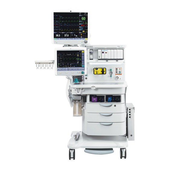
Aisys CS² Figure 1-1 • Front view Serial numbers Datex-Ohmeda products have unit serial numbers with coded logic which indicates a product group code, the year of manufacture, and a sequential unit number for identification. The serial number can be in one of two formats. -
Page 17: Trademarks
1 Introduction AAAX11111 AAAXX111111AA The X represents an alpha character The XX represents a number indicating the year the product was indicating the year the product was manufactured; H = 2004, J = 2005, manufactured; 04 = 2004, 05 = 2005, etc. -
Page 18: Symbols Used In The Manual Or On The Equipment
Aisys CS² Symbols used in the manual or on the equipment Symbols replace words on the equipment, on the display, or in product manuals. Warnings and Cautions tell you about dangerous conditions that can occur if you do not follow all instructions in this manual. Warnings tell about a condition that can cause injury to the operator or the patient. - Page 19 1 Introduction Operating instructions General warning (yellow background) Electrical input/output Sample gas inlet to scavenging Pneumatic inlet Pneumatic outlet Equipotential Lamp, lighting, illumination Variability Variability in steps Suction bottle outlet Vacuum inlet Bag position/manual ventilation Mechanical ventilation Inspiratory flow Expiratory flow Movement in one direction Movement in two directions Lock...
- Page 20 Aisys CS² Indicates that the waste of electrical GOST R Russian certification and electronic equipment must not be disposed as unsorted municipal waste and must be collected separately. Please contact an authorized representative of the manufacturer for information concerning the decommissioning of equipment.
-
Page 21: Symbols Used On The User Interface
1 Introduction Atmospheric limitation Symbols used on the user interface Lock Lock/unlock button Indicates the touchscreen is locked. Button label to lock or unlock the touchscreen. O2% indicator on left and balance gas Gas indicator. Color associated with gas indictor on right. Colors associated with settings. -
Page 22: Typeface Conventions Used
Aisys CS² Typeface conventions used Soft keys and menu items are written in bold italic typeface; for example, System Setup. Messages that are displayed on the screen are enclosed in single quotes; for example, ‘Check sample gas out’. When referring to different sections and other documents, the names are written in italic typeface and enclosed in double quotes;... -
Page 23: Abbreviations
1 Introduction Abbreviations Abbreviation Definition Anesthetic agent Advanced breathing system ACGO Auxiliary common gas outlet AGSS Anesthesia gas scavenging system Alt O2 Alternate O2 Adjustable pressure-limiting Apnea ATPD Ambient temperature and pressure, dry humidity conditions BTPS Body temperature, ambient pressure, saturated humidity conditions Common gas outlet Carbon monoxide... - Page 24 Aisys CS² Abbreviation Definition Minimum alveolar concentration Minute volume MVexp Expired minute volume MVinsp Inspired minute volume Nitrous oxide Oxygen Airway pressure Pressure control ventilation PCV-VG Pressure control ventilation - volume guaranteed PEEP Positive end expiratory pressure Paw-Flow Pressure-flow loop Pinsp Inspiratory pressure Pmax...
- Page 25 1 Introduction Abbreviation Definition Volume control ventilation Volume 1-13 2067226-001...
-
Page 26: System Information
Aisys CS² System information System classification This system is classified as follows: • Class I Equipment. • Type B Equipment. • Type BF Equipment (airway modules). • Ordinary Equipment. • Not for use with flammable anesthetics. • Continuous operation. Device standards IEC 60601-1:2005 Devices used with this anesthesia system shall comply with the following standards where applicable: •... -
Page 27: Integral System Components
1 Introduction Integral system components This anesthesia system contains the following integral components, monitoring devices, alarm systems, and protection devices that comply with European, international, and national standards: • Breathing system pressure-measuring device. • Airway pressure-limitation device. • Exhaled-volume monitor. •... -
Page 28: System Safety
Aisys CS² System safety Preparing for use WARNING Read each component’s User’s Reference manual and understand the following before using this system: • All system connections. • All warnings and cautions. • How to use each system component. • How to test each system component. •... -
Page 29: Inspecting The System
1 Introduction device containing phthalates is used for treatment of children or treatment of pregnant or nursing women: • Exchange transfusion in neonates, total parenteral nutrition in neonates, multiple procedures in sick neonates, haemodialysis in peripuberal males, male fetus and male infant of pregnant women, and lactating women;... -
Page 30: Electrical Safety
Aisys CS² • Pipeline gas supplies are connected and the pressures are correct. • Cylinder valves are closed. • Models with cylinder supplies have a cylinder wrench attached to the system. • Models with cylinder supplies have a reserve supply of O2 connected to the machine during system checkout. - Page 31 1 Introduction supplied from an AC power source which uses a separating transformer (in accordance with IEC 60989) or be provided with an additional protective earth conductor. • If a portable multiple socket outlet assembly is used as an AC power source, it must comply with IEC 60601-1-1.
- Page 32 1-20 2067226-001...
-
Page 33: System Controls And Menus
2 System controls and menus System controls and menus In this section System overview........2-2 Advanced breathing system components. -
Page 34: System Overview
Aisys CS² System overview Patient monitoring modules Aladin cassette storage bay Dovetail Brake Aladin cassette and active bay O2 flush button Light switch Advanced breathing system Alternate O2 control Auxiliary O2 flow control System switch Anesthesia display Mains indicator Patient monitoring display Integrated suction Figure 2-1 •... - Page 35 2 System controls and menus Serial port Mains inlet Collection bottle connection System circuit breaker Cylinder wrench (key) storage Equipotential stud Cylinder yoke Outlet circuit breaker Anesthesia Gas Scavenging System Isolated electrical outlet Pipeline connections Figure 2-2 • Rear view 2067226-001...
-
Page 36: Using The Brake
Aisys CS² Using the brake The central brake holds the system in place. WARNING Do not use the brake while moving the anesthesia system. This could cause the machine to tip over. Only use the brake to keep the system in place. Push down on the brake pedal to lock the system in place. - Page 37 2 System controls and menus Tilt the display left or right to adjust the horizontal angle of the display. 2067226-001...
-
Page 38: Advanced Breathing System Components
Aisys CS² Advanced breathing system components Expiratory check valve Breathing system release Inspiratory check valve Manual bag port Inspiratory flow sensor Adjustable pressure-limiting (APL) valve Expiratory flow sensor Bag/Vent switch Absorber canister Bellows assembly Absorber canister release Airway module Leak test plug Figure 2-3 •... -
Page 39: Using The Bag Support Arm
2 System controls and menus Bag support arm Auxiliary Common Gas Outlet (ACGO) switch ACGO port EZchange canister module (CO2 bypass) Ezchange canister release Condenser Condenser drain button Figure 2-4 • Breathing system options Using the bag support arm Use the optional bag support arm to hold the breathing circuit bag. To raise the bag support arm, squeeze the button and rotate the arm up the top position. -
Page 40: Aladin Cassette Controls
Aisys CS² Aladin cassette controls The electronically controlled vaporizer consists of the internal electronic control unit and the Aladin agent cassette. See the "Vaporizer" section for more information. Handle with release trigger Lock Liquid level indicator Agent filling port Figure 2-5 • Aladin2 cassette 2067226-001... -
Page 41: Display Controls
2 System controls and menus Display controls The system uses touchscreen technology, hard keys, and a ComWheel to access system functions, menus, and settings. The touchscreen has numerous touch point areas that make accessing menus and settings quick and easy. The buttons on the right side of the screen provide direct access to commonly used functions. -
Page 42: Touch Points
Aisys CS² Audio Pause key Stops audio for 120 seconds for any active, eligible high and medium priority alarms. Prevents audio (audio off) for 90 seconds when no medium or high priority alarms are active. Allows the operator to acknowledge any non-active medium or high priority latched alarms. -
Page 43: Active Alarm Touch Points
2 System controls and menus Touch the measured value to access the Alarm Setup menu. The Alarm Setup menu displays. Select the alarm limit and set it to the correct value. Touch the value on the touchscreen or push the ComWheel to confirm the desired setting. -
Page 44: Anesthesia System Display
Aisys CS² Anesthesia system display Audio pause symbol and Indicates when alarm audio is paused and the countdown clock until audio is countdown clock Alarm message fields Displays the active alarms. Waveform fields Displays the waveforms of measured values. For example: Paw, Flow, and CO2. -
Page 45: Digit Fields
2 System controls and menus 11. Gas quick keys Displays O2, Total Flow, and Gas Setup. 12. Split screen Contains airway pressure, gas flow values, compliance, trends, and optional ecoFLOW information. Figure 2-8 • Typical Normal/Full view Digit fields The digit field can be set to show specific information such as gas types, gas supply, flow, agent, respiration, and spirometry loops. - Page 46 Aisys CS² Touch the spilt screen field to directly open the Screen Setup menu. See "Screen setup menu" in the "Operation" section for more information. 2-14 2067226-001...
-
Page 47: Display Navigation
2 System controls and menus Display navigation Use the touchscreen and ComWheel to navigate the display. Menu Displays the title of the open menu. For example: Start Case. Instructions or help information This shows any additional instructions or help messages. Menu items Shows Case Defaults, Volume Apnea Alarm, CO2 Alarms, Age, Ideal Weight, and Start Case Now. -
Page 48: Using The Comwheel
Aisys CS² Select a menu item to choose the item, or turn the ComWheel left or right to highlight a menu item and then push to confirm. If the menu item selected is an adjustment, turn the ComWheel left or right to make the setting and then push to confirm. If the menu item has a drop-down list, select the desired value from the list by touching the item. -
Page 49: Operation
3 Operation Operation In this section System operation safety......3-2 Turning on the system......3-3 Start a case. -
Page 50: System Operation Safety
Aisys CS² System operation safety WARNING Do not use antistatic or electrically-conductive breathing tubes or masks. They can cause burns if used near high- frequency surgical equipment. • Explosion Hazard. Do not use this system with flammable anesthetic agents. • Ventilator alarms indicate potential hazard conditions. -
Page 51: Turning On The System
3 Operation Turning on the system Plug the power cord into an electrical outlet. Make sure the system circuit breaker is on. • The mains indicator is lit when AC power is connected. • Battery is charging if it is not already fully charged. System switch Mains indicator Figure 3-1 •... -
Page 52: Start A Case
Aisys CS² Start a case Use the Start Case menu to set the case data and to start the gas flow. A case can be started using default settings or using custom settings. The default settings are configured by the Super User. See the "Super user mode"... -
Page 53: Starting A Case Using Default Settings
3 Operation The adjusted MAC value shows on several areas of the screen including in the mini-trend, agent waveform numeric information, agent digit field, and graphical trends page. Starting a case using default settings Start a case using the default settings by case type defined by the Super User. -
Page 54: End A Case
Aisys CS² To change ventilation mode, select Mode. Make the change.To change the ventilation settings, select a ventilator quick key or More Settings. Make the change. To change alarm settings, select Alarm Setup. Make the change. To change the gas settings or the circuit type, select Gas Setup. Make the change. -
Page 55: Turning Off The System
3 Operation Turning off the system Perform the "End a case" procedure, if appropriate. Turn the System switch to Standby. Turn the suction switch (optional) to the off position. Rotate the Auxiliary O2 knob fully clockwise to turn off the flow. Disconnect or turn off any scavenging. -
Page 56: Ventilator Setup
Aisys CS² Ventilator setup Use the Vent Mode menu to set the ventilation mode. Use ventilator quick keys and More Settings to change ventilator settings. WARNING Most anesthetic agents will cause patients to have reduced ventilatory responses to carbon dioxide and to hypoxemia. -
Page 57: Auto Limits
3 Operation Auto limits Use the Auto Limits menu to quickly set alarm ranges for ‘MV’, ‘TV’, and ‘EtCO2’ during mechanical ventilation. Setting auto limits Select Auto Limits. The menu shows the current measured values and the proposed low and high alarm limits. Check the proposed parameters. -
Page 58: Gas Setup
Aisys CS² Gas setup Use the Gas Setup menu to adjust the Agent, O2% and total flow, to change the balance gas, and to change the circuit type. Changing gas settings Select the Gas Setup quick key. Select the setting to change from the Gas Setup menu. Change the setting. - Page 59 3 Operation Using the circle circuit Use the circle circuit mode to combine fresh gas with recirculated gas from the CO2 absorber. The combined gas flows out through the inspiratory port. Patient gas is returned to the system through the expiratory port.
- Page 60 Aisys CS² Set the alarm limits to clinically appropriate settings. 3-12 2067226-001...
-
Page 61: System Setup
3 Operation System setup Use System Setup to access menus and settings for Patient Demographics, Screen Setup, Fresh Gas Usage, System Status, Calibration, and Checkout. Note System Status shows the status of gas supplies, electrical supplies, and the software version. See the "User maintenance"... - Page 62 Aisys CS² Select System Setup - Screen Setup. Select the Layout tab. Select the desired digit field button and select the value from the drop-down menu. Select Close. Setting the split screen Use the Split Screen setting to show metabolics, trends, spirometry loops, Paw gauge, airway compliance, and optional ecoFLOW information.
- Page 63 3 Operation Select Patient to have spirometry data sourced from the airway module or Vent to have spirometry data sourced from the ventilator. Select Back to view changes made and access other functions of the Spirometry menu. Setting sweep speed Use the Sweep Speed setting to set the waveform draw rate to fast (6.25 mm/s) or slow (0.625 mm/s).
-
Page 64: Fresh Gas Usage
Aisys CS² Setting fresh gas controls Use the Fresh Gas Controls selection to set the gas control style to O2% with Total Flow or to individual gas flow. Selecting O2% shows O2% as the first quick key and Total Flow l/min as the second quick key. -
Page 65: Alarm Setup
3 Operation Alarm setup Use the Alarm Setup menu to set and adjust alarm limits, alarm volume, and other alarm settings and to view alarm history. The Alarm Setup menu contains the Primary Limits, More Limits, Alarm History, and Configure submenus. Setting Leak Audio to Off silences audio alarms for small leaks. -
Page 66: Setting Mv Tv Alarms
Aisys CS² To turn the volume apnea alarms off, select Vol Apnea Alarm to Off. ‘Volume Apnea Off’ shows in the general message field. • If mechanical ventilation is started, the volume apnea alarms are active. • If manual ventilation is restarted, a pop-up confirmation window appears to resume the Off setting. -
Page 67: Viewing Alarm History
3 Operation Viewing alarm history Use the Alarm History tab to view the list of the 12 most recent high and medium priority alarms that occurred since the start of the case. The alarm history clears at the start of a new case. Select Alarm Setup. -
Page 68: Setting Auto Mv Limits
Aisys CS² Set Leak Audio to Off. The audio alarms for small leaks are silenced. To turn audio alarms back on, set Leak Audio to On. Select Close. Note If the Low MV alarm limits are off or MV/TV Alarms is set to Off, Leak Audio is automatically set to On and cannot be changed. -
Page 69: Alarms On Off
3 Operation Alarms On Off Use the Alarms On/Off menu to turn On or turn Off the CO2 Alarms Limits and MV/TV Alarm Limits during manual ventilation. Alarm limits are enabled at the start of mechanical ventilation. Note The CO2 ‘Apnea’ alarm cannot be turned off through the Alarms On/Off menu. -
Page 70: Next Page
Aisys CS² Next page Select Next Page to change the screen view. A default view and four configurable screen views are available. A general message displays identifying the page number of the screen view. See the "Super user mode" section for information on setting the preset screen views. -
Page 71: Trends
3 Operation Trends Use the Trends menu to view patient trends and set the time scale. There are three views for patient trends: measured (numerical), settings, and graphical. Trend information is saved every 15 seconds for the most recent 24 hours. Setting trends Select Trends. -
Page 72: Spirometry
Aisys CS² Spirometry Use the Spirometry menu to: • Set the loop type. • Adjust the loop scaling. • Save a loop to memory. • Access the Setup Loops menu. • View a saved loop. • Delete a saved loop. There are three types of spirometry loops: Pressure-Volume (Paw- Vol), Flow-Volume (Flow-Vol), and Pressure-Flow (Paw-Flow). -
Page 73: Setting Loop Graph Scaling
3 Operation Setting loop graph scaling Use Spirometry Scaling to set the scales of the spirometry loop graph. The available settings for the volume, Paw, and flow graph axes are dependent on the set patient type of adult or pediatric. •... -
Page 74: Setting Spirometry Volume Type
Aisys CS² Select System Setup - Screen Setup - More Settings or Spirometry - Setup Loops. Select Data Source. Select Patient to have spirometry data sourced from the airway module or Vent to have spirometry data sourced from the ventilator. Select Back to view changes made and access other functions of the Spirometry menu. -
Page 75: Procedures
3 Operation Procedures Use the Procedures menu to pause the gas flow, start cardiac bypass, perform or change settings for a vital capacity procedure, or perform or change the settings for a cycling procedure. Note Vital Capacity shows in the menu if it is set to Yes by the Super User. -
Page 76: Vital Capacity
Aisys CS² WARNING Manual ventilation cardiac bypass and VCV cardiac bypass modes should only be used when the patient is receiving extra-corporeal oxygenation by means of a heart-lung machine. These modes of ventilation are not intended to provide metabolic levels of ventilation to the patient. -
Page 77: Cycling
3 Operation The Pressure Hold, Hold Time, and PEEP on Exit settings can be preset by the Super User. These settings can be changed by the user before starting the procedure. Note PEEP on Exit shows if it is set to Yes by the Super User. Using vital capacity Select Procedures. - Page 78 Aisys CS² Select Cycling. Select a Procedure to perform. Select Start Cycling. The procedure begins. Procedure progress shows in the procedure window. Stop the procedure anytime by selecting Stop Cycling. Select Close. Changing cycling settings Select Procedures. Select Cycling. Select a Procedure to perform. Select Adjust Settings.
-
Page 79: Timer Function
3 Operation Timer function Use Start as a timer function. When selected a clock will display counting up from zero. Using the timer Select Start to start the clock. Select Stop to pause or stop the clock. If Start is selected, the clock will resume operation. If Start is selected and held for longer than 1 second, the clock will reset to zero. -
Page 80: Ecoflow
Aisys CS² ecoFLOW This feature provides a split screen view that shows the approximate minimum O2 flow to maintain a preset inspired O2 concentration. Also shown is the approximate agent used per hour and the cost. Total Flow Agent 21.91 O2 Total 1.30 Fi25 O2 flow... -
Page 81: Using Ecoflow
3 Operation Using ecoFLOW Select System Setup - Screen Setup. Select the Layout tab. Select Split Screen and select ecoFLOW from the drop-down menu. Select Close. 3-33 2067226-001... -
Page 82: Alternate O2 Control
Aisys CS² Alternate O2 control WARNING The Alternate O2 control is not an auxiliary source of O2. • When Alternate O2 control is enabled, flow from the electronic mixer is stopped and the agent concentration is set to off. O2 is flowing through the Alternate O2 control to the breathing system. - Page 83 3 Operation Use the flow control to adjust the O2 flow. Set the agent to the desired concentration. To end Alternate O2 control, push the Alternate O2 ON/OFF button. 3-35 2067226-001...
-
Page 84: Ezchange Canister Mode
Aisys CS² EZchange canister mode Use the optional EZchange canister mode for continued ventilation of the patient while changing the absorber canister. The EZchange canister mode seals the breathing circuit when the canister holder is down. While the absorber canister is out of the breathing circuit, the patient re-breaths exhaled gases without any gas passing through the absorbent. -
Page 85: Using Ezchange Canister Mode
3 Operation Using EZchange canister mode Note Make sure that the absorber canister has side rails. If the canister does not have side rails, it will not work in the EZchange canister holder. Push the absorber canister release to activate the EZchange canister mode. -
Page 86: Condenser
Aisys CS² Condenser Use the optional condenser to remove water in the system that is produced from the reaction of CO2 gas with the absorbent. The condenser is connected between the outlet of the absorber canister and the inlet of the circuit module. Moisture in the gas is condensed into water droplets, which run into the condenser’s reservoir. - Page 87 3 Operation Push the drain button to empty any water in the condenser. 3-39 2067226-001...
-
Page 88: Auxiliary Common Gas Outlet
Aisys CS² Auxiliary Common Gas Outlet Use the optional Auxiliary Common Gas Outlet (ACGO) switch to direct the fresh gas flow through the ACGO port on the front of the system. The ACGO may be used to provide fresh gas to an auxiliary manual breathing circuit. - Page 89 3 Operation Note A sample of the fresh gas is diverted to the O2 cell in the breathing system. The sample flow to the O2 cell is dependent on the pressure in the external circuit. The sample flow reduces the fresh gas flow rate to the auxiliary breathing circuit equal to the amount diverted to the O2 cell.
- Page 90 3-42 2067226-001...
-
Page 91: Preoperative Checkout
4 Preoperative checkout Preoperative checkout In this section Every day before your first patient....4-2 Before every patient....... 4-3 2067226-001... -
Page 92: Every Day Before Your First Patient
Aisys CS² Every day before your first patient □ Check that necessary emergency equipment is available and in good condition. □ Check that the equipment is not damaged and that components are correctly attached. □ Check that the pipeline gas supplies are connected. If equipped with cylinders, check that there is sufficient reserve capacity and that the cylinder valve is closed. -
Page 93: Before Every Patient
4 Preoperative checkout Before every patient Note This check does not need to be done before the first case of the day if the "Every day before your first patient" checklist was done. □ Check that the necessary emergency equipment is available and in good condition. - Page 94 2067226-001...
-
Page 95: Preoperative Tests
5 Preoperative tests Preoperative tests In this section Aladin cassette installation......5-2 Flow and pressure calibration......5-3 Circuit compliance compensation. -
Page 96: Aladin Cassette Installation
Aisys CS² Aladin cassette installation Using the liquid level indicator, check that the cassette is filled to the appropriate level. If using Aladin2, unlock the cassette handle before installing it into the active bay. Insert the cassette into the active bay until a click is heard. An audible click indicates that the cassette is in position. -
Page 97: Flow And Pressure Calibration
5 Preoperative tests Flow and pressure calibration Important Room temperature fluctuations of more than 5°C may affect sensor measurements. Recalibrate the flow sensors if the room temperature changes by more than 5°C. Calibrate the flow sensors by removing the flow sensor module from the system. -
Page 98: Circuit Compliance Compensation
Aisys CS² Circuit compliance compensation The ventilator adjusts gas delivery and monitoring to compensate for the compliance of the patient circuit if: • The system has an airway module installed. • The Circuit Compliance is set to On from Super User - System Config. -
Page 99: Checkout Menu
5 Preoperative tests Checkout menu The Checkout menu shows on the display after turning on the system. To access the Checkout menu between cases, select Checkout. Step-by-step instructions show in the Checkout menu during the tests. Use the Checkout menu to: •... -
Page 100: Full Test
Aisys CS² Full test The Full Test or the individual tests must be performed at least once within every 24-hour period. Perform the Full Test at the start of each day. The full test runs automatically and beeps to indicate when it is finished or if interaction is required. -
Page 101: Circuit O2 Cell
5 Preoperative tests Circuit O2 cell The Circuit O2 Cell test measures the O2 percent. To run this test, follow the on-screen instructions. Do not select Done when 21 is first displayed. Allow the reading to stabilize, then select Done. Calibrate the O2 cell if necessary. External gas monitor When External Gas Monitor is set to Yes by the Super User, the External Gas Monitor reminder occurs. -
Page 102: Individual Tests
Aisys CS² Individual tests The Full Test or all of the individual tests must be completed with passing results at least once within every 24-hour period. Individual tests allow the user to perform any combination of single tests. These tests are helpful if there is a specific problem/alarm and the user wishes to test only that portion of the system. -
Page 103: Low P Leak (Machines With Acgo)
5 Preoperative tests To run this test, follow the on-screen instructions. Low P leak (machines with ACGO) The negative Low P Leak measures machine leaks before the breathing system, between the common gas outlet and the high- pressure pneumatics and includes the gas mixer and vaporizer. It measures low pressure pneumatic leaks with a pass or fail limit of 50 Note Any cassette may be used during the check. -
Page 104: Positive Low Pressure Leak Test (Acgo Systems Only)
Aisys CS² Positive low pressure leak test (ACGO systems only) Note For ACGO machines, perform either a negative Low P Leak test or a positive low-pressure leak test depending on local requirements. CAUTION Do a positive-pressure leak test at the ACGO port only. Connect the leak test device to the ACGO port with the positive- pressure leak test adapter. - Page 105 6 Airway modules Airway modules In this section Airway modules........6-2 Connecting the airway module.
-
Page 106: Airway Modules
Leaks in the gas sampling circuit (water trap and sampling line) may cause inaccurate readings. CAUTION Use only cables and accessories approved by GE Healthcare Finland Oy. Other cables and accessories may damage the system or interfere with measurement. Single-use accessories are not designed to be reused. -
Page 107: Airway Modules
6 Airway modules Letters in the airway module name indicate: • E - E series plug-in gas module. • M - M series plug-in gas module. • E-s - CARESCAPE series plug-in gas module. • C - CO2 and N2O. •... -
Page 108: Carescape Airway Modules
Aisys CS² CARESCAPE airway modules Water trap latch Gas sample connector D-fend Pro water trap Connectors for patient spirometry Sample gas outlet Figure 6-2 • CARESCAPE airway module (figure may not represent all models) 2067226-001... -
Page 109: Connecting The Airway Module
6 Airway modules Connecting the airway module Check that the airway gas module is installed. Check that the airway adapter connections are tight and that the adapter is correctly installed. Check that the water trap container is empty and properly attached. -
Page 110: Parameters Setup
Aisys CS² Parameters setup Use the Spirometry menu to change the monitoring settings of the data source, CO2, O2, agent, and spirometry. To access the Spirometry menu, push the Spirometry button and then select Setup Loops. Data source Several monitoring parameters can be obtained from the ventilator or the airway module. -
Page 111: Automatic Agent Identification
6 Airway modules Automatic agent identification Airway modules with agent identification automatically identify Halothane, Enflurane, Isoflurane, Sevoflurane, and Desflurane. The inspiratory and expiratory concentrations of the agent appear in the digit field or the agent waveform field if selected. Minimum concentration for the identification is 0.15% volume. The agent selection remains active even if the concentration decreases below 0.15% volume during the case. -
Page 112: Calibrating The Airway Module
Aisys CS² Calibrating the airway module Calibrate airway modules once every six months or whenever there are indications of errors in the gas readings. Use a manufacturer approved calibration gas and regulator to calibrate the modules. See the "Parts" section for the stock numbers of the calibration gas and regulator. -
Page 113: Alarms And Troubleshooting
7 Alarms and troubleshooting Alarms and troubleshooting In this section Alarms......... . 7-2 List of alarms. -
Page 114: Alarms
Aisys CS² Alarms Alarms may be high priority, medium priority, or low. When an alarm occurs during a case, an alarm tone sounds and the alarm message is displayed in the alarm message field. The system checks for alarm conditions at 1 second intervals. The alarm tone is from 47 to 78 db(A) depending on the alarm volume setting. -
Page 115: Cancelling Audio Pause
7 Alarms and troubleshooting Cancelling audio pause Selecting and holding Audio Pause for 2 seconds will cancel the audio pause function. Display changes during alarms Messages may appear in the waveform field during some alarms. If more than one alarm has a message, the message for the highest priority alarm is displayed. -
Page 116: Internal Failure
Aisys CS² • Red indicates less than 5 minutes. Internal failure ‘Internal problem prevents normal operation.’ shows on the display during a software or hardware failure that requires service. If this message occurs, contact an authorized service representative. Informational tones The system provides informational tones that are 47 to 78 dB(A) depending on the alarm volume setting. -
Page 117: List Of Alarms
7 Alarms and troubleshooting List of alarms If corrective action does not resolve the alarm message, contact an authorized service representative. Circuit pressures and volumetric flows are measured by the ventilator and airway gas module. If the Data Source is set to Patient the displayed waveforms and numeric information are measured by the airway gas module. - Page 118 Aisys CS² Message Priority Cause Action Backup Mode No spontaneous breaths in set period Select a new ventilation mode. The active of time (Backup Time) since starting number of consecutive patient triggered PSVPro mode. breaths reaches the Exit Backup setting. Breathing system The breathing system is not latched.
- Page 119 7 Alarms and troubleshooting Message Priority Cause Action Circuit leak Setting on Alarm Setup menu. Vent Check the patient. Make sure Leak silenced TVexp is less than 50% of vent TVinsp Audio Off is the appropriate setting for for at least 30 seconds and Leak Audio the case.
- Page 120 Aisys CS² Message Priority Cause Action EtSev high Medium EtSev is greater than alarm limit. The Set the alarm limits appropriately. alarm priority escalates to High if the Check agent setting. alarm is not resolved after 2 minutes. EtSev low EtSev is less than alarm limit.
- Page 121 7 Alarms and troubleshooting Message Priority Cause Action Increase low MV Medium Low MV limit is off in SIMV VCV, SIMV Increase low MV alarm limit to improve limit PCV, SIMV PCV-VG, CPAP + PSV, or patient disconnection detection. PSVPro modes. Insert cassette Cassette removal detected during Reinsert the cassette.
- Page 122 Aisys CS² Message Priority Cause Action O2 monitoring not Medium O2 cell not connected. Install airway gas module or connect the connected O2 cell. O2 supply High O2 pipeline pressure is less than 252 Ensure the O2 pipeline and cylinder are pressure low kPa (36 psi) and the O2 cylinder properly connected.
- Page 123 7 Alarms and troubleshooting Message Priority Cause Action System leak? Leak detected between ventilator and Check for leaks in the breathing system. patient circuit. System shutdown High Remaining battery power is between Plug in the power cable. Check that the in <...
-
Page 124: Sustained Pressure Threshold
Aisys CS² Message Priority Cause Action Ventilator has no High Drive gas supply is not sufficient to Check drive gas supply. Use a manual drive gas mechanically ventilate. bag to ventilate the patient until drive gas supply is restored. Vol and Apnea Non circle circuit is selected. -
Page 125: Alarm Ranges
7 Alarms and troubleshooting Alarm ranges The alarm names are listed in the Primary Limits and More Limits tabs on the Alarm Setup menu. See the "Super user mode" section for more information on the alarm default settings. Alarm Range Increment Pmax (only high) 12-100 cmH2O... - Page 126 Aisys CS² Alarm Range Increment EtIso Low Off, 0.1 - 6.9% 0.1% EtSev High 0.1 - 10.0%, Off 0.1% EtSev Low Off, 0.1 - 9.9% 0.1% EtDes High 0.1 - 20%, Off 0.1% EtDes Low Off, 0.1 - 19.9% 0.1% EtEnf High 0.1 - 7.0%, Off 0.1%...
-
Page 127: Alarm Tests
7 Alarms and troubleshooting Alarm tests Test the system to verify that alarms are functioning. Note If an airway module is installed, the FiO2 readings are taken from the module instead of from the O2 cell. A sample line must be connected from the airway module to the breathing circuit to test the O2 alarms. - Page 128 Aisys CS² • Unblock the patient connection. • Set the Bag/Vent switch to Vent. • Set the tidal volume and total flow to minimum. • Other alarms such as MVexp low can occur. • Make sure that the Ppeak low. Leak? alarm occurs. 10.
-
Page 129: Breathing System Problems
7 Alarms and troubleshooting Breathing system problems Symptom Problem Solution Gas scavenging flow is too low Scavenging extract flow problem. Use a different scavenging extraction or too high. system. Verify flow is within specification. Filter blockage. Active systems have Replace the filter. Refer to “Remove the a flow indicator. -
Page 130: Electrical Problems
Aisys CS² Electrical problems WARNING If a circuit breaker opens frequently, do not use the system. Contact an authorized service representative to repair the system. Symptom Problem Solution Mains indicator is not on. The electrical power cable is not Connect the power cable. connected. -
Page 131: Pneumatic Problems
7 Alarms and troubleshooting Pneumatic problems Symptom Problem Solution High-pressure leak test fails. Controls are not set correctly. Make sure no gas is flowing, turn off the auxiliary flow meter, and repeat the test. Incorrect cylinder connection. Make sure that there is only one cylinder gasket, the gasket is in good condition, and the connection is tight. - Page 132 7-20 2067226-001...
-
Page 133: Setup And Connections
8 Setup and connections Setup and connections In this section Setup safety........8-2 Moving and transporting the system. -
Page 134: Setup Safety
• React with the anesthetic gases or agent to produce dangerous by-products. • Use only GE Healthcare approved cables, hoses, and tubing. Other manufacturer’s cables, hoses, and tubing could cause incorrect values or equipment malfunction. • Do not exceed electrical interference levels specified in IEC 60601-1-2. - Page 135 8 Setup and connections • Use only breathing tubes that comply with EN12342 or ISO 5367 on this system. • A malfunction of the medical gas central supply system may cause all connected devices to stop. • All gases supplied to the system must be medical grade. Use of non-medical grade gases could result in equipment damage.
-
Page 136: Moving And Transporting The System
Aisys CS² Moving and transporting the system WARNING The system may overbalance or tip if tilted more than 10 degrees. • Do not exceed specified load ratings when mounting equipment on the top of the machine or on any of the side rails. -
Page 137: Setting Up The Absorber Canister
8 Setup and connections Setting up the absorber canister The absorber canister is available in two versions: Disposable Multi Absorber and Reusable Multi Absorber. Both are removed and installed on the breathing system the same way. Each canister holds 800 grams of loose absorbent. The manufacturer recommends Medisorb TM absorbent. -
Page 138: When To Change The Absorbent
Aisys CS² Reusable Multi Absorber canister Figure 8-1 • Canister WARNING Obey applicable safety precautions: • Do not use the absorber with chloroform or trichlorethylene. • The Disposable Multi Absorber is a sealed unit which should not be opened or refilled. •... -
Page 139: Removing A Canister
8 Setup and connections Immediately discard the absorbent if it has changed color. If left standing for several hours, absorbent may regain its original color giving a misleading indication of effectiveness. Read the absorbent manufacturer’s instructions completely before using the product. Removing a canister Hold the canister by the handle and push on the release latch to unlock the canister. -
Page 140: Filling The Reusable Multi Absorber Canister
Aisys CS² Filling the Reusable Multi Absorber canister Turn the canister upside down and, using your thumbs, turn the cover locking ring counterclockwise to unlock it. Push up to release the seal. Lift off the cover to remove it. Remove and properly discard the foam filters, the absorbent, and any water in the reservoir. - Page 141 8 Setup and connections To clean and disinfect the canister, refer to “Absorbent canister cleaning” in the “Cleaning and Sterilization” manual. Place a new filter in the bottom of the canister, pour absorbent into the canister and place a new filter over the absorbent before closing and locking the cover.
-
Page 142: Electrical Connections
Aisys CS² Electrical connections Mains inlet The arrow shows the mains power inlet and cord. Equipotential stud The equipotential stud is used to connect the anesthesia machine to an equipotential grounding system by attaching a potential equalization conductor. Equipotential grounding is used in some hospitals to enhance electrical safety in critical care areas by attempting to keep the conductive surfaces of all equipment in the patient care area at the same ground potential, thereby minimizing... -
Page 143: Serial Port
8 Setup and connections Serial port The system has a Universal Serial Bus (USB) port on the back of the display unit. This port is for use by authorized service personnel to load software and access log files. It should not be used for other purposes. -
Page 144: Pneumatic Connections
Aisys CS² Pneumatic connections CAUTION Use only medical grade gas supplies. Other types of gas supplies may contain water, oil, or other contaminants which could affect the operation of the pneumatic system. The gas supplies provide gas to these devices through internal connections: •... - Page 145 8 Setup and connections Auxiliary inlet Sample gas scavenging port Outlet connection Figure 8-2 • AGSS connections Scavenging the ACGO sample flow When the ACGO port is in use, a sample of the fresh gas is diverted to the airway module or the O2 cell in the breathing system. This sample is then measured and displays the O2 numerics on the screen.
-
Page 146: Sample Gas Return Port
Aisys CS² Scavenging from an auxiliary manual breathing circuit Scavenge the exhaust if an auxiliary manual circuit is used with N2O or volatile anesthetics. An auxiliary inlet is available on the AGSS. It provides a female connection for use with a 30 mm - 30 mm male connector (or 30 mm - 19 mm male connector) under the breathing system. -
Page 147: Pneumatic Power Outlet
8 Setup and connections Pneumatic power outlet Vacuum suction regulator (optional) The vacuum suction regulator uses an external vacuum supply. Connect the vacuum connection to the source vacuum supply. Connect the collection bottle connection to the collection bottle. External vacuum connection Overflow safety trap Splash guard Collection bottle connection... -
Page 148: Venturi Suction Regulator (Optional)
Aisys CS² Venturi suction regulator (optional) The venturi suction regulator uses the system air or O2 supply source. Connect the collection bottle connection on the overflow safety trap to the collection bottle. Venturi muffler Overflow safety trap Splash guard Collection bottle connection Figure 8-4 •... - Page 149 8 Setup and connections Auxiliary O2 flow control Figure 8-5 • Auxiliary O2 flowmeter 8-17 2067226-001...
-
Page 150: Installing Gas Cylinders
Aisys CS² Installing gas cylinders CAUTION Do not leave gas cylinder valves open if the pipeline supply is in use. Cylinder supplies could be depleted, leaving an insufficient reserve supply in case of pipeline failure. Installing cylinders with pin indexed yokes Locate the cylinder wrench. - Page 151 8 Setup and connections Turn off the auxiliary O2 flowmeter and venturi suction. Open the cylinder. Record the cylinder pressure. Close the cylinder. If the cylinder pressure decreases more than 690 kPa (100 psi) in one minute there is a significant leak. To repair a leak, install a new cylinder gasket and tighten the adapter.
-
Page 152: Attaching Equipment To The Top Of The Machine
Aisys CS² Attaching equipment to the top of the machine WARNING The top of the machine has a weight limit of 45 kg (100 lb). • Check the stability of the system in its final configuration. Make sure the weight is evenly distributed throughout the system. -
Page 153: Passive Agss
8 Setup and connections Passive AGSS WARNING Always verify the proper operation of any gas scavenging system. Make sure that the scavenging system is not occluded. The optional passive anesthesia gas scavenging system (AGSS) is for use in operating room environments that do not have an active gas extraction system for waste gas disposal. -
Page 154: Active Agss
Aisys CS² Active AGSS WARNING Always verify the proper operation of any gas scavenging system. Make sure the scavenging system is not occluded. There are several versions of the optional active Anesthesia Gas Scavenging System (AGSS) available depending on the hospital’s type of waste gas disposal system. -
Page 155: Connecting Active Adjustable Agss
8 Setup and connections Connect the proper hose to the AGSS outlet connector on the bottom of the AGSS underneath the breathing system. Attach the other end of the hose to the hospital disposal system. With the AGSS operating, verify that the ball on the flow indicator rises to the green zone, indicating adequate flow. - Page 156 Aisys CS² flow rate. The bag should remain partially inflated when the flow rate is adequate. Complete the tests in the "Preoperative tests" section. 8-24 2067226-001...
-
Page 157: User Maintenance
9 User maintenance User maintenance In this section Maintenance safety....... .9-2 Repair policy. -
Page 158: Maintenance Safety
Aisys CS² Maintenance safety WARNING To help prevent fires: • Do not use lubricants that contain oil or grease. They may burn or explode in high O2 concentrations. • All covers used on the system must be made from antistatic (conductive) materials. Static electricity can cause fires. -
Page 159: Repair Policy
Equipment damage could occur. Replace damaged parts with components manufactured or sold by GE Healthcare. Then test the unit to ascertain that it complies with the manufacturer’s published specifications. Contact the local authorized Field Service Representative for service assistance. -
Page 160: Maintenance Summary And Schedule
Aisys CS² Maintenance summary and schedule These schedules indicate the minimum frequency of maintenance based on typical usage of 2000 hours per year. Service the equipment more frequently if it is used more than the typical yearly usage. Note Local policies or regulations may require that maintenance be performed more frequently than stated here. -
Page 161: Circuit O2 Cell Replacement
9 User maintenance Circuit O2 cell replacement WARNING Handle and dispose of O2 cells according to site biohazard policies. Do not incinerate. Note It may take a new O2 cell 90 minutes to stabilize. If the O2 cell calibration fails after a new O2 cell had been installed, wait 90 minutes and repeat the calibration. -
Page 162: Calibration Menu
Aisys CS² Calibration menu Access the Calibration menu by selecting the System Setup button. Follow the instructions on the screen. Note The Calibration menu is not available during Checkout or during a case. See "Calibrating the airway module" in the "Airway modules" section for information on calibrating the airway modules. -
Page 163: Airway Gas Calibration
9 User maintenance Follow the instructions on the screen. Airway gas calibration The airway gas selection is only available on the Calibration menu when the system detects an airway module and the module has completed the warm up phase. See the "Airway modules" section for calibration instructions. - Page 164 2067226-001...
-
Page 165: 10 Parts
10 Parts Parts In this section Flow sensor module......10-2 Breathing circuit module......10-3 Bellows. -
Page 166: Flow Sensor Module
Aisys CS² Flow sensor module Item Description Stock number Flow sensor module (does not include flow 1407-7022-000 sensors) Flow sensor cover 1011-3283-000 Flow sensor cuff 1407-3004-000 Flow sensor, disposable (plastic) 1503-3858-000 Flow sensor, autoclavable (metal) 1503-3244-000 10-2 2067226-001... -
Page 167: Breathing Circuit Module
10 Parts Breathing circuit module Item Description Stock number Breathing circuit module (does not include O2 1407-7002-000 cell or plug, o-ring, or cable) Check valves circuit lens 1407-3101-000 Check valve assembly 1406-8219-000 O-ring for O2 cell or plug 1406-3466-000 O2 cell (includes o-ring) 6050-0004-110 Cable, O2 cell 1009-5570-000... -
Page 168: Bellows
Aisys CS² Bellows Item Description Stock number Bellows housing M1239264 Bellows 1500-3378-000 1500-3351-000 Pressure relief valve assembly 1500-3377-000 Latch, rim 1500-3352-000 Seal, base 1500-3359-000 Manifold, bellows base 1407-3702-000 Poppet, APL valve 1406-3332-000 Cage, APL 1406-3333-000 Diaphragm, APL 1406-3331-000 Ramp, APL 1407-3400-000 Bellows base with latch, green M1213265... -
Page 169: Complete Advanced Breathing System
10 Parts Complete advanced breathing system Description Stock number Complete breathing assembly includes: • Flow sensor module (does not include flow sensors). • Breathing circuit module (does not include APL valve, O2 cell or plug, o-ring, or cable). • Complete bellows base. •... -
Page 170: Absorber Canister
Aisys CS² Absorber canister Item Description Stock number Multi absorber, reusable (includes 40 pack of 1407-7004-000 foam; does not include absorbent) Cover assembly, CO2 canister 1009-8240-000 Foam, CO2 canister (pack of 40) 1407-3201-000 O-ring 1407-3204-000 Canister, CO2 with handle 1407-3200-000 Multi absorber, disposable, white to violet (pack 8003138 of six) -
Page 171: Exhalation Valve Assembly
10 Parts Exhalation valve assembly Description Stock number Exhalation valve assembly 1407-7005-000 10-7 2067226-001... -
Page 172: Agss
Aisys CS² AGSS Description Stock Number Common Cap 3.18 barb silicone 1406-3524-000 Connector, inlet 30 mm male to 19 mm male M1003947 Connector, inlet 30 mm male to 30 mm male M1003134 O-ring for connector, 21.95 ID 1406-3558-000 O-ring for receiver, 22 ID 1407-3104-000 O-ring for thumbscrews, 4.47 ID 1407-3923-000... - Page 173 10 Parts Description Stock Number Active AGSS, low flow Filter, 225 micrometer nylon screen AGSS 1406-3521-000 Seal, filter scavenger 1407-3902-000 10-9 2067226-001...
-
Page 174: Ezchange Canister System
Aisys CS² EZchange canister system Item Description Stock number EZchange canister module, includes valve and 1407-7021-000 Valve 1407-7023-000 1407-3130-000 Condenser 1407-7024-000 EZchange canister module with condenser 1407-7027-000 10-10 2067226-001... -
Page 175: Condenser
10 Parts Condenser Item Description Stock number Condenser assembly (includes module and 1407-7026-000 condenser) Condenser module 1407-7025-000 Condenser 1407-7024-000 10-11 2067226-001... -
Page 176: Test Tools And System Parts
Aisys CS² Test tools and system parts Description Stock number Airway module calibration gas 755583 Airway module calibration gas (U.S. variant only) 755571 Airway module exhaust line 8004463 Calibration gas regulator 755534 Calibration gas regulator (U.S. variant only) M1006864 Cylinder gasket (pin indexed cylinders only) 0210-5022-300 Cylinder wrench (DIN477 and high-pressure hose) 1202-3651-000... -
Page 177: Specifications And Theory Of Operation
11 Specifications and theory of operation Specifications and theory of operation In this section System pneumatic circuit......11-2 Pneumatic specifications. -
Page 178: System Pneumatic Circuit
Aisys CS² System pneumatic circuit 11-2 2067226-001... - Page 179 11 Specifications and theory of operation Auxiliary O2, 0-10 l/min (optional) Inspiratory flow sensor 241 kPa (35 psi) secondary O2 regulator Patient wye (patient connection) Pipeline: O2, Air, N2O Airway transducer Cylinder: O1, Air, N2O Inspiratory flow transducer 758 kPa (110 psi) relief Expiratory flow transducer Venturi drive gas connection Manifold pressure transducer...
-
Page 180: Gas Supplies
Aisys CS² Gas supplies Pressurized gas supplies enter the system through a pipeline or cylinder connection. All connections have indexed fittings, filters, and check valves. A regulator decreases the cylinder pressures to the appropriate system pressure. A pressure relief valve helps protect the system from excessive high pressures. -
Page 181: Mixed Gas
11 Specifications and theory of operation Mixed gas Either Air or N2O can be selected as the balance gas. The balance gas flow is controlled by the mixer. When Alternate O2 control is in use, only O2 is flowing and balance gas is disabled. The mixed gas goes from the mixer outlet through the vaporizer to the fresh gas outlet and into the breathing system. -
Page 182: Pneumatic Specifications
Aisys CS² Pneumatic specifications CAUTION All gases supplied to the system must be medical grade. Gas supplies Pipeline gases O2, Air, N2O Cylinder gases O2, Air, N2O (3 cylinder maximum) Cylinder connections Pin indexed Nut and gland DIN-477 Large cylinder kit available for O2 and N2O Primary regulator output Pin indexed: The primary regulator is set to pressure... -
Page 183: Pneumatic Power Outlet
11 Specifications and theory of operation Pneumatic power outlet The pneumatic outlet is supplied with the same gas supply pressure as the attached oxygen medical gas pipeline supply. The anesthesia system is rated for supply pressures between 280 kPa - 600 kPa. The anesthesia system is designed to function normally with a maximum flow of 8 l/min from the pneumatic outlet. -
Page 184: Electrical Block Diagram
Aisys CS² Electrical block diagram Power cord Flow control valve with cable AC inlet and breaker Gas inlet valve with cable Inrush board Expiratory and inspiratory flow sensors Transformer O2 cell Fuse block Light strip boards Outlet box with breakers Light strip switch Agent delivery board CGO valve... - Page 185 11 Specifications and theory of operation Airway module power supply board LCD with touch screen Airway module O2 flush switch Display carrier board and CPU DC power in Speaker 1 Communication to system Speaker 2 ComWheel encoder Display unit fan with cable Cassette temperature sensor board Network I/O port - 1 (Ethernet) Inflow zero valve...
-
Page 186: Electrical Power
Aisys CS² Electrical power Supply voltage 100-120, 220-240, or 120/220-240 Vac +/- 10% at 50 or 60 Hz Inlet circuit 100-120 Vac 220-240 Vac 120/220-240 Vac breakers 15 A Outlet circuit 110-120 Vac Japan 220-240 Vac breakers (3) 2 A (2) 2 A (3) 1 A (1) 3 A... - Page 187 11 Specifications and theory of operation • The system functions to specifications through the transition to battery power. The system will automatically switch over to the battery supply when adequate system supply cannot be maintained from the mains input. • The system functions to specifications while the battery is recharging.
-
Page 188: Flow Specifications
Aisys CS² Flow specifications Alternate O2 Minimum flow 500 ml/min to 700 ml/min Maximum flow 10 l/min to 13 l/min Indicator Flow tube Indicator accuracy +/- 5% full scale Fresh gas Flow range 0 and 200 ml/min to 15 l/min Minimum total flow O2 and balance gas is 200 ml/min Total flow accuracy... -
Page 189: Breathing System Specifications
11 Specifications and theory of operation Breathing system specifications Volume Ventilator side 2730 ml; bag side 1215 ml With EZchange canister system and condenser: ventilator side 3145 ml; bag side 1630 ml Absorbent 1250 ml canister Connections Auxiliary Common Gas Outlet: ISO 5356 type connector on the front of the system (standard 22 mm OD or 15 mm ID conical friction fit connectors). -
Page 190: Gas Scavenging
Aisys CS² Inspiratory Breathing resistance in bag mode* l/min cmH2O 0.06 0.21 0.49 *Values include patient circuit tubing and wye-piece 0.049 kPa (0.5 cmH2O) at 60 l/min. Patient circuit tubing and breathing system configurations affect resistance. Expiratory Breathing resistance in bag mode* l/min cmH2O 0.05... - Page 191 11 Specifications and theory of operation Passive scavenging Negative pressure relief 0.3 cmH2O Outlet connector 30 mm male taper ISO Active scavenging Disposal system Outlet Flow range Pressure type connector* Adjustable DISS EVAC Up to 30 l/min not applicable High flow, low BSI 30 mm 50 to 80 l/min not applicable...
-
Page 192: Physical Specifications
Aisys CS² Physical specifications All specifications are approximate values and can change without notice. CAUTION Do not subject the system to excessive shock and vibration. • Do not place excessive weight on flat surfaces or drawers. WARNING Maintain system balance. When using rails or dovetails, distribute equipment on each side of the system. -
Page 193: Upper Dovetail Loading
11 Specifications and theory of operation Figure 11-1 • Lower dovetail load in kg (vertical) versus load distance from the lower dovetail in cm (horizontal). Upper dovetail loading Maximum allowable upper dovetail loading is 11.3 kg and 54 Nm. See "System overview" for the location of the upper dovetail. Figure 11-2 •... -
Page 194: Environmental Requirements
Aisys CS² Environmental requirements Operation Storage and Transport Temperature 10 to 35°C -25 to 60°C Oxygen cell 10 to 40°C Oxygen cell storage is -15 to 50°C, 10 to 95% RH, 500 to 800 mmHg LCD display storage is -20 to 60°C Aladin cassette storage is -25 to 50°C Humidity 15 to 95% RH, non-condensing... -
Page 195: Airway Module Specifications
11 Specifications and theory of operation Airway module specifications Use only airway modules that have anesthetic agent monitoring and O2 monitoring on this system. The following modules can be used on this system: • E-series: E-CAiO, E-CAiOV, E-CAiOVX (software version 4.5 and above) •... -
Page 196: Gas Specifications For Carescape Modules
Aisys CS² Gas specifications for CARESCAPE modules CARESCAPE Airway humidity 0 to 100% condensing Sampling delay 3.0 seconds typical with a 3 m sampling line Total system response time Less than 3.8 seconds with a 3 m sampling line Warm-up time 1 minute for operation with CO2, O2, and N2O 5 minutes for operation of anesthetic agents Respiration rate... -
Page 197: Typical Performance
11 Specifications and theory of operation Typical performance M- and E-series CARESCAPE* Measurement range 0 to 15 vol% (0 to 15 kPa, Measurement range 0 to 15 vol% (0 to 15 kPa, 0 to 113 mmHg). 0 to 113 mmHg). Measurement rise time less than 400 ms Measurement rise time less than 260 ms typical. -
Page 198: Suction Regulators (Optional)
Aisys CS² Suction regulators (optional) Venturi Suction Regulator Performance Category Pharyngeal Suction Supply Air or O2 from system gas supply Drive Gas Consumption* 28 l/min with pipeline drive gas at 280 kPa 52 l/min with pipeline drive gas at 600 kPa Maximum Vacuum* 600 mmHg with pipeline drive gas at 280 kPa 550 mmHg with pipeline drive gas at 600 kPa... -
Page 199: Ventilator Theory
11 Specifications and theory of operation Ventilator theory The ventilator pneumatics are at the rear of the breathing system. A precision valve controls gas flow to the patient. During inspiration, this gas flow closes the exhalation valve and pushes the bellows down. -
Page 200: Ecoflow Theory Of Operation
Aisys CS² The voltage from the cell cartridge is affected by the temperature of the monitored gas mixture. A thermistor in the cell’s housing automatically compensates for temperature changes in the cell. O2 monitoring uses signal processing and analyzing circuitry to convert the cell signal into a corresponding percent oxygen value. - Page 201 11 Specifications and theory of operation • Synchronized intermittent mandatory ventilation - volume control ventilation (SIMV VCV) • Synchronized intermittent mandatory ventilation - pressure control ventilation (SIMV PCV) • Synchronized intermittent mandatory ventilation - pressure control ventilation - volume guaranteed (SIMV PCV-VG) •...
- Page 202 Aisys CS² Texp PEEP Flow waveform Figure 11-3 • Volume control waveform Pressure control mode (PCV) Pressure control ventilation supplies a constant set pressure during inspiration. The ventilator calculates the inspiratory time from the frequency and I:E ratio settings. A high initial flow pressurizes the circuit to the set inspiratory pressure.
- Page 203 11 Specifications and theory of operation Flow waveform Figure 11-4 • Pressure control waveform PCV-VG mode In PCV-VG, a tidal volume is set and the ventilator delivers that volume using a decelerating flow and a constant pressure. The ventilator will adjust the inspiratory pressure needed to deliver the set tidal volume breath-by-breath so that the lowest pressure is used.
- Page 204 Aisys CS² Texp Variable pressure to deliver desired TV PEEP Flow waveform Figure 11-5 • PCV-VG waveforms SIMV VCV mode Synchronized intermittent mandatory ventilation with volume control is a mode in which periodic volume breaths are delivered to the patient at preset intervals (time-triggered). Between the machine delivered breaths, the patient can breathe spontaneously at the rate, tidal volume, and timing that the patient desires.
- Page 205 11 Specifications and theory of operation Mandatory SIMV breath Spontaneous pressure supported breath Psupport PEEP Time Figure 11-6 • SIMV VCV waveform SIMV PCV mode Synchronized intermittent ventilation with pressure control ventilation (SIMV PCV) delivers a relatively slow breathing rate with pressure- controlled breathing.
- Page 206 Aisys CS² Paw waveform Tinsp Spontaneous breathing period Trigger window Pressure supported breath Pinsp Flow waveform Figure 11-7 • SIMV PCV waveforms SIMV PCV-VG mode Synchronized intermittent mandatory ventilation with pressure control volume guaranteed (SIMV PCV-VG) delivers a set rate of pressure controlled breaths with a guaranteed volume to the patient.
- Page 207 11 Specifications and theory of operation breaths will be pressure controlled with a guaranteed volume at the inspiratory limb. A portion of the exhalation phase is defined as the trigger window. If a spontaneous breath is detected in this window, a new mandatory PCV-VG breath is initiated.
- Page 208 Aisys CS² PEEP Flow waveform Figure 11-8 • SIMV PCV-VG waveforms PSVPro mode PSVPro is pressure supported ventilation with apnea backup. PSVPro is a spontaneous mode of ventilation that provides a constant support pressure once the ventilator senses that the patient has made an inspiratory effort.
- Page 209 11 Specifications and theory of operation • Pinsp • • Tinsp • Rise Rate • Exit Backup PEEP Time Figure 11-9 • PSVPro waveform When the ventilator switches to the backup mode, the ‘Backup Mode active’ alarm shows until PSVPro is reinstated or until another ventilation mode is selected.
- Page 210 Aisys CS² inspiration termination is set to 30% then the ventilator will stop inspiration when the flow decelerates to a level equal to 30% of the measured peak inspiratory flow. The lower the setting the longer the inspiratory time and conversely, the higher the setting the shorter the inspiratory phase.
-
Page 211: Ventilation Modes Factory Default Settings
11 Specifications and theory of operation Ventilation modes factory default settings The ventilation mode factory default settings for the ADULT case default show in the following table. An * indicates the setting is not used for the ventilation mode. See the "Super user mode" section for all other case default values. -
Page 212: Ventilation Mode Transition
Aisys CS² Ventilation mode transition Ventilation settings selectable though the quick keys and More Settings are set to the factory default settings at start up of the system and at the end of each case. The ventilation settings remain at the factory default until changed by the user. If a ventilation setting is changed, the new setting remains active in all applicable modes until the setting is changed again. -
Page 213: Ventilator Operating Specifications
11 Specifications and theory of operation Ventilator operating specifications Based on the ventilator settings in use, the setting ranges may be constrained so that the specifications stated are met. Pneumatics Gas source Anesthesia system Gas composition Medical Air or O2 Nominal supply pressure 350 kPa (50 psi) Pressure range at inlet... -
Page 214: Oxygen
Aisys CS² Minute volume less than 0.1 to 99.9 liters, 0.1 liter resolution Breath rate 4 to 100 bpm (non-spontaneous) 2 to 60 bpm (spontaneous) 1 bpm resolution Volume sensor type Variable flow orifice Oxygen Display range 5 to 110% O2 Display resolution 1% increments Sensor type... -
Page 215: Ventilator Accuracy Data
11 Specifications and theory of operation Ventilator accuracy data The following accuracy data is based on patient conditions and settings described in ASTM F1101. The ventilator is assumed to be operating in volume mode. For the following to be true, the ventilator is operating with 100 percent oxygen in the breathing system, or it is connected to an anesthesia gas analyzer. -
Page 216: Electronically Controlled Vaporizer And Aladin Cassette
Aisys CS² Electronically controlled vaporizer and Aladin cassette Electronically controlled vaporizer for delivery of five agents: halothane, isoflurane, enflurane, sevoflurane, and desflurane. The cassettes can be handled safely without excessive leakage of anesthetic agent to the environment. The electronically controlled vaporizer is calibrated using 100% O2 at multiple flows. - Page 217 11 Specifications and theory of operation +20%, +1.0% v/v +10%, +0.5% v/v -10%, -0.5% v/v 18-25C 10-35C -20%, -1.0% v/v Accuracy is greater of percent of setting (%) or volumetric percent (% v/v) Fresh gas flow ml/min All settings Settings equal to or less than 13.4% Settings equal to or less than 9% Settings equal to or less than 3.6% Figure 11-13 •...
- Page 218 Aisys CS² Accuracy is greater of percent of setting (%) or volumetric percent (% v/v) Fresh gas flow ml/min All settings Settings equal to or less than 3.8% Figure 11-14 • Enflurane accuracy +20%, +0.4% v/v +10%, +0.2% v/v -10%, -0.2% v/v 18-25C 10-35C -20%, -0.4% v/v...
- Page 219 11 Specifications and theory of operation +20%, +0.4% v/v +10%, +0.2% v/v -10%, -0.2% v/v 18-25C 10-35C -20%, -0.4% v/v Accuracy is greater of percent of setting (%) or volumetric percent (% v/v) Fresh gas flow ml/min All settings Settings equal to or less than 4.0% Settings equal to or less than 1.6% Figure 11-16 •...
-
Page 220: Aladin2 Cassettes
Aisys CS² Aladin2 cassettes Filling Filling system Easy-Fil: Adapter filler system for isoflurane, enflurane, and sevoflurane. Quick-Fil: Filler system compatible to Abbot’s system for sevoflurane. Saf-T-Fill: Filler system compatible to the Datex-Ohmeda Saf-T-Fil bottle for desflurane. Filling speed Greater than 2 ml/s Overfilling protection Overfilling prevention systems built into the cassettes. - Page 221 11 Specifications and theory of operation Liquid capacity Normal fill when indicator shows empty 150 ml (residual volume 100 ml) Cassette Empty weight 2 kg: enflurane, isoflurane, sevoflurane with keyed filler 2.5 kg: halothane with keyed filler, sevoflurane with Quik-Fil 3 kg: desflurane Height 7 cm...
-
Page 222: Electromagnetic Compatibility (Emc)
Aisys CS² Electromagnetic compatibility (EMC) WARNING Changes or modification to this equipment not expressly approved by the manufacturer could cause EMC issues with this or other equipment. Contact the manufacturer for assistance. This device is designed and tested to comply with applicable regulations regarding EMC as follows. -
Page 223: Guidance And Manufacturer's Declaration - Electromagnetic Emissions
11 Specifications and theory of operation Display optional output Cables used for EMC testing ports Monitor On/STBY Standard 9-pin D-subminiature male connector with shielded cable - 1.8 m maximum length. Guidance and manufacturer’s declaration - electromagnetic emissions The system is suitable for use in the specified electromagnetic environment. -
Page 224: Power Immunity
Aisys CS² Power immunity Power immunity Immunity test IEC 60601-1-2 test level Compliance level Electromagnetic environment guidance Electrostatic discharge +/- 6 kV contact +/- 6 kV contact Floors should be wood, concrete, or (ESD) IEC 61000-4-2 +/- 8 kV air +/- 8 kV air ceramic tile. - Page 225 11 Specifications and theory of operation Radiated immunity Immunity test IEC 60601-1-2 test level Compliance level Electromagnetic environment guidance recommended separation distance Conducted RF IEC 3 Vrms 10 Vrms (V1) D=0.35√P 61000-4-6 150 kHz to 80 MHz outside ISM bands 10 Vrms 10 Vrms (V2) D=1.2√P...
-
Page 226: Recommended Separation Distances
Aisys CS² Recommended separation distances The system is intended for use in the electromagnetic environment in which radiated RF disturbances are controlled. The customer and/or user of the system can help prevent electromagnetic interference by maintaining a minimum distance between portable and mobile RF communications equipment (transmitters) and the system as recommended below, according to the maximum power of the communications equipment. -
Page 227: 12 Super User Mode
12 Super user mode Super user mode In this section Super user mode....... . 12-2 Gas usage. -
Page 228: Super User Mode
Aisys CS² Super user mode WARNING Do not enter Super User mode when a patient is connected to the system. Gas flow will cease, and the system must be powered down in order to restart gas flow. • Changes made in Super User mode affect the system configuration. -
Page 229: Gas Usage
12 Super user mode Gas usage Use the Gas Usage menu to view the total fresh gas usage since the last reset, to reset the gas usage to zero, and view optional ecoFLOW and agent cost information. Resetting cumulative gas usage From Super User mode, select Gas Usage and then Cumulative Gas Usage. - Page 230 Aisys CS² Select Back to return to the Gas Usage menu. 12-4 2067226-001...
-
Page 231: System Configuration
12 Super user mode System configuration Use the System Config. menu to set default information for the system. Use the System Config. menu to access menus and settings for Colors, Units, Ventilator Settings, Alarm Settings, Parameter Settings, Trends Setup, and Pages Setup. Display settings Use the Colors menu to set the default colors for waveforms, digit fields, and trends. -
Page 232: Alarm Settings
Aisys CS² Select the item to change. Set VCV Cardiac Bypass to Yes to enable alveolar support during cardiac bypass. This menu item is only available on systems with the VCV Cardiac Bypass option installed. Set Circuit Compliance to On to allow tidal volume compensation for circuit compliance. - Page 233 12 Super user mode Setting principal setting defaults From Super User mode, select System Config. and then Parameter Settings. Select the item to change. For Principal Volume, select MV or TV from the drop-down list. For Principal O2, select Et or Fi from the drop-down list. For Principal Agent, select Et or Fi from the drop-down list.
-
Page 234: Trends Setup
Aisys CS² Trends setup Use the Trends Setup menu to set the default trend graphical page layout for the top, middle, and bottom trends for each page shown in the user’s Trends menu. Setting the default trend type From Super User mode, select System Config. and then Trends Setup. - Page 235 12 Super user mode Setting page views The table shows the factory default settings for each page view. Default settings for Page view setup Page 1 Page 2 Page 3 Page 4 Middle Flow Flow Flow Bottom Left Loops Loops Middle Left Resp Resp...
-
Page 236: Case Defaults
Aisys CS² Case defaults Use the Case Defaults menu to set the default case types that show on the Start Case menu and access the Volume Apnea Setup menu. Configuring case defaults Set the case defaults for the case types that are selectable from the Start Case menu. -
Page 237: Default Case Type Settings
12 Super user mode Select Volume Apnea Setup. Set Volume Apnea Selection to Enable or Disable. Set to Enable to allow the user to turn the volume apnea alarm on or off from the Start Case menu. Set to Disable to set the volume apnea alarms as always on during manual ventilation. - Page 238 Aisys CS² Page 1 Default settings for default case types Settings ADULT PEDIATRIC LOCAL CUSTOM 1 Volume Apnea Page 2 Default settings for default case types Settings ADULT PEDIATRIC LOCAL CUSTOM 1 Vent Mode Minimum RR Tpause PEEP Page 3 Default settings for default case types Settings ADULT PEDIATRIC...
- Page 239 12 Super user mode Page 5 Default settings for default case types Settings ADULT PEDIATRIC LOCAL CUSTOM 1 Bottom Waveform Split Screen Left Digit Field Loops Loops Loops Loops Middle Left Digit Resp Resp Resp Resp Field Middle Right Digit Agent Agent Agent...
- Page 240 Aisys CS² Page 7 Default settings for default case types Settings ADULT PEDIATRIC LOCAL CUSTOM 1 EtEnf Low EtEnf High FiEnf Low FiEnf High Page 8 Default settings for default case types Settings ADULT PEDIATRIC LOCAL CUSTOM 1 EtHal Low EtHal High FiHal Low FiHal High...
-
Page 241: Gas Controls
12 Super user mode Gas controls Use the Gas Controls menu to set the user’s Agents, Total Flow, and O2% quick select preset values and the Fresh Gas Controls setting. Setting gas preset values Set five preset gas values that will show on the user’s Gas Setup menu for Agents, O2%, and Total Flow. -
Page 242: Procedures Setup
Aisys CS² Procedures setup Use the Procedures menu to set the procedures available to the user. From this menu select the default settings for Vital Capacity and Cycling procedures. Setting vital capacity defaults From Super User mode, select Procedures. Select Vital Capacity. Set Show Vital Capacity to Yes to show this menu item on the user’s Procedures menu. - Page 243 13 Vaporizer cassettes Vaporizer cassettes In this section Vaporizer........13-2 Changing a cassette during a case.
-
Page 244: Vaporizer
Aisys CS² Vaporizer The electronically controlled vaporizer consists of the internal electronic control unit and the Aladin agent cassette. The agent cassettes are color coded, have indexed filling ports, and are magnetically coded for each agent. The electronic control unit governs the flow through the agent cassette and the agent concentration in the fresh gas flow. -
Page 245: Aladin Cassette Variants
13 Vaporizer cassettes Figure 13-1 • Aladin2 desflurane cassette with Saf-T-Fil system Figure 13-2 • Aladin2 cassette for enflurane, isoflurane, and sevoflurane with Easy-Fil or Quik-Fil system Aladin cassette variants Aladin desflurane cassettes have electronic agent level sensing. No other Aladin cassettes have electronic level sensing. The agent level shows graphically in the agent settings area of the screen. - Page 246 Aisys CS² When electronic level sensing is unavailable for an Aladin cassette, the agent level unknown symbol shows in the agent settings area of the screen. In this case, refer to the liquid level indicator. There are three types of Aladin cassette filler systems. Halothane, enflurane, and isoflurane use color-coded, keyed fillers.
- Page 247 13 Vaporizer cassettes Figure 13-4 • Aladin cassette for sevoflurane with Quik-Fill system Figure 13-5 • Aladin cassette for desflurane with Saf-T-Fil compatible filler system 13-5 2067226-001...
-
Page 248: Changing A Cassette During A Case
Aisys CS² Changing a cassette during a case Push the Agent quick key. Set agent delivery to off. Turn the lock on the handle to the vertical position (Aladin2 cassettes only). Remove cassette from the active bay. • Store the cassette in the cassette storage bay if it will not be used. -
Page 249: Removing A Cassette
13 Vaporizer cassettes Removing a cassette Use the Changing a cassette during a case procedure when changing a cassette while a case is in progress. Turn the lock on the handle to the vertical position (Aladin2 cassettes only). Remove the cassette from the active bay. Store the cassette in the cassette storage bay if it will not be used. -
Page 250: Installing A Cassette
Aisys CS² Installing a cassette Using the liquid level indicator, check that the cassette is filled to the appropriate level. If using Aladin2, unlock the cassette handle before installing it in the active bay. Insert the cassette into the active bay until a click is heard, ensuring the cassette is in the correct position. -
Page 251: Cassette Maintenance
13 Vaporizer cassettes Cassette maintenance Clean and drain the cassettes as recommended. Cleaning CAUTION Do not wipe the cassette with alcohol or alcohol-based detergents. This may damage the surface of the cassette. Remove the cassette from the system. Clean the cassette surface with a cloth moistened in a mild soap solution. -
Page 252: Draining Halothane Cassettes
Aisys CS² Draining halothane cassettes The decomposition of halothane causes the release of halides, which may corrode metal components particularly in the presence of moisture. A preservative, added to halothane by its manufacturers to impede decomposition, can leave a residue which may cause cassette components to stick. -
Page 253: Filling Aladin2 Cassettes
13 Vaporizer cassettes Filling Aladin2 cassettes Remove the cassette from the machine before filling the cassette. Make sure that the cassette remains in a horizontal position during filling. If the cassette is tilted, the flow of liquid is shut off to prevent overfilling. - Page 254 Aisys CS² Figure 13-6 • Aladin2 cassette with Easy-Fil system WARNING Do not open or press the cassette filling port or the gas connection valves with fingers or any kind of instrument. Anesthetic agent liquid or gas may squirt into the air. Remove the cassette from the machine, and place it on a horizontal surface.
-
Page 255: Filling With Quik-Fil System
13 Vaporizer cassettes Note Removing the bottle quickly may cause the agent to splash or squirt out of the filling port. Put the cap back on the filling port. Remove the bottle adapter from the anesthetic agent bottle. Put the cap back on the agent bottle. Filling with Quik-Fil system Figure 13-7 •... -
Page 256: Filling With Saf-T-Fill Bottle
Aisys CS² • When the liquid level indicator reaches the full mark, slowly remove the bottle from the filling port. Note Removing the bottle quickly may cause the agent to splash or squirt out of the filling port. Put the cap back on the filling port. Put the cap back on the agent bottle. - Page 257 13 Vaporizer cassettes Remove the cassette from the machine, and place it on a horizontal surface. Make sure that the valve pins on the back of the cassette do not come in contact with the machine or any other object. Remove the cap from the desflurane bottle.
-
Page 258: Filling Aladin Cassettes
Aisys CS² Filling Aladin cassettes Remove the cassette from the machine before filling the cassette. Make sure that the cassette remains in a horizontal position during filling. If the cassette is tilted, the flow of liquid is shut off to prevent overfilling. -
Page 259: Filling With Quik-Fil System
13 Vaporizer cassettes the cassette do not come in contact with the machine or any other object. Align the notches on the bottle adapter to the agent bottle collar and tight the adapter onto the bottle. Insert the keyed filler into the agent filling port on the cassette. Make sure that the square end of the filler is flus with the cassette body as shown. -
Page 260: Filling With Saf-T-Fil Bottle
Aisys CS² Remove the cassette from the machine, and place it on a horizontal surface. Make sure that the valve pins on the back of the cassette do not come in contact with the machine or any other object. Remove the yellow protective cap from the anesthetic agent bottle. - Page 261 13 Vaporizer cassettes WARNING Do not store filled or partially filled desflurane cassettes above the normal working temperature of 35C/95F. Storage at high temperature may cause the overpressure valve to vent desflurane vapor into the ambient air. • Do not open or press the cassette filling port or the gas connection valves with fingers or any kind of instrument.
- Page 262 13-20 2067226-001...
- Page 263 Index Alarm history 3-19 Alarm setup Abbreviations 1-11 Auto MV limit 3-20 Absorbent canister CO2 alarms 3-17 canister removal 8-7 default limits 3-20 EZchange canister removal 8-7 leak audio alarms 3-19 filling the canister 8-8 MV/TV alarms 3-18 Absorbent color change 8-6 setting alarm limits 3-18 Absorber canister setting apnea delay 3-19...
- Page 264 Aisys CS² VCV 3-28 Exhalation valve assembly Changing circuit type 3-10 parts 10-7 Changing gas settings 3-10 EZchange canister Changing ventilator mode 3-8 filling the canister 8-8 Changing ventilator settings 3-8 parts 10-10 Checkout removal 8-7 individual tests 5-8 Circle circuit 3-11 Circuit Flow and pressure calibration 5-3, 9-6 circle 3-10...
- Page 265 Index Pressure control mode 11-26 Procedures MAC 3-4 Cycling 3-27 Maintenance Vital Capacity 3-27 repair policy 9-3 PSVPro mode 11-32 safety 9-2 schedule 9-4 Measured values 2-10 Minimum Alveolar Concentration (MAC) 3-4 Repair policy 9-3 MV/TV alarms 3-18 Sample gas return port 8-14 Next page 3-22 Scavenging Non-circle circuit 3-11...
- Page 266 Aisys CS² Start a case 3-4 Typeface conventions 1-10 Suction regulators specifications 11-22 Super User menus USB port 8-11 alarm settings 12-6 Using menus 2-15 case defaults 12-10 Using quick keys 2-16 display settings 12-5 Using the ComWheel 2-16 gas controls 12-15 gas usage 12-3 parameter settings 12-6 procedures setup 12-16...
- Page 267 Warranty This Product is sold by Datex-Ohmeda under the warranties set forth in the following paragraphs. Such warranties are extended only with respect to the purchase of this Product directly from Datex-Ohmeda or Datex-Ohmeda’s Authorized Dealers as new merchandise and are extended to the Buyer thereof, other than for the purpose of resale.
- Page 268 Aisys CS² User's Reference Manual English 2067226-001 06 13 C 18 05 02 Printed in USA...
Need help?
Do you have a question about the auisys cs2 and is the answer not in the manual?
Questions and answers
Manufactor instructions of flushing the unit for known or susceptible patient with malignant hyperthermia on the GE Aisys CS2