
Related Manuals for Qsan AegisSAN Q500 Series


Summary of Contents for Qsan AegisSAN Q500 Series
- Page 1 Qsan Document - User Manual AegisSAN Q500 Series AegisSAN V100 Series AegisSAN LX Series JBOD Series Version 8.52 October 2014...
- Page 2 Qsan Document – User Manual Copyright Copyright@2004~2014, Qsan Technology, Inc. All rights reserved. No part of this document may be reproduced or transmitted without written permission from Qsan Technology, Inc. Trademarks All products and trade names used in this manual are trademarks or registered trademarks of their respective companies.
-
Page 3: Preface
Preface About This Manual This manual is the introduction of Qsan storage system and it aims to help users know the operations of the disk array system easily. Information contained in this manual has been reviewed for accuracy, but not for product warranty because of the various environments / OS / settings. -
Page 4: Conventions
This device has been shown to be in compliance with and was tested in accordance with the measurement procedures specified in the Standards and Specifications listed below and as indicated in the measurement report number: xxxxxxxx-E Technical Standard: EMC DIRECTIVE 2004/108/EC Copyright@2004~2014 Qsan Technology, Inc. All Rights Reserved. - Page 5 Access is through the use of a TOOL or lock and key, or other means of security, and is controlled by the authority responsible for the location. Copyright@2004~2014 Qsan Technology, Inc. All Rights Reserved.
- Page 6 Las baterí as pueden explotar si no se manipulan de forma apropiada. No desmonte ni tire las baterí as al fuego. Siga las normativas locales al desechar las baterí as agotadas. 警告: (Simplified Chinese) 本电池如果更换不正确会有爆炸的危险,请依制造商说明处理用过之电 池。 警告: (Traditional Chinese) 本電池如果更換不正確會有爆炸的危險,請依製造商說明處理用過之電 池。 Copyright@2004~2014 Qsan Technology, Inc. All Rights Reserved.
-
Page 7: Table Of Contents
Drive Slot Numbering ........................45 System Installation and Deployment ....................46 ON / OFF ............................60 OWER Power on the System ........................60 Power off the System ........................60 Chapter 3 QUICK SETUP............................63 Copyright@2004~2014 Qsan Technology, Inc. All Rights Reserved. - Page 8 Snapshots ............................109 Logical Units ............................ 112 QReplicas ............................114 ........................... 116 NCLOSURE ANAGEMENT Hardware Monitor .......................... 116 UPS ..............................118 SES ..............................119 S.M.A.R.T............................120 ..........................120 YSTEM AINTENANCE System Information ........................120 Copyright@2004~2014 Qsan Technology, Inc. All Rights Reserved.
- Page 9 LACP ........................... 144 RUNKING AND LACP ..............................144 Trunking ............................145 ............................. 146 ONTROLLERS Perform I/O ............................. 146 Ownership ............................147 Controller Status ..........................147 Change Controller Mode ......................... 148 Recommend iSNS Server ......................... 148 Copyright@2004~2014 Qsan Technology, Inc. All Rights Reserved.
- Page 10 Solution ............................171 Methodology ........................... 171 Populating the Cache ........................172 Read/Write Cache Cases ......................... 172 I/O Type ............................174 Configuration ..........................176 Constraint............................177 Chapter 6 TROUBLESHOOTING .......................... 178 ............................178 YSTEM UZZER Copyright@2004~2014 Qsan Technology, Inc. All Rights Reserved.
- Page 11 Setup MC/S ............................. 190 Disconnect ............................192 VSS ............................193 ICROSOFT lntroduction ............................ 193 Software Contents .......................... 193 Install MPIO, VSS Software ......................193 Using QVSSClient..........................196 GLOSSARY AND ACRONYM LIST ..........................199 INDEX ................................201 Copyright@2004~2014 Qsan Technology, Inc. All Rights Reserved.
-
Page 12: Chapter 1 Overview
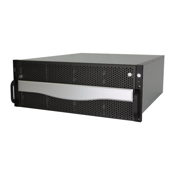
Qsan Document – User Manual Overview Product Overview This user manual describes how to set up and use the Qsan storage systems. There are several types of chassis available now. AegisSAN Q500 Series: AegisSAN Q500 AegisSAN Q500 (2U12bays) (3U16bays) AegisSAN Q500... -
Page 13: Model Comparison
SAS interfaces, provides a flexible, intelligent, storage area network (SAN) solution for virtualized server environments and the glowing demand for data storage. Qsan storage systems can provide non-stop service with a high degree of fault tolerance by using Qsan RAID technology and advanced array management features. - Page 14 Q500-F20-S424 4 x 8Gb FC (SFP+) Q500-F21-D212 Q500-F21-D316 Q500-F21-D424 + 2 x GbE iSCSI Q500-F21-S212 Q500-F21-S316 Q500-F21-S424 2 x 16Gb FC (SFP+) Q500-F30-D212 Q500-F30-D316 Q500-F30-D424 + 2 x GbE iSCSI Q500-F30-S212 Q500-F30-S316 Q500-F30-S424 Copyright@2004~2014 Qsan Technology, Inc. All Rights Reserved.
-
Page 15: Package Contents
HDD trays (x12) (2U12). HDD trays (x16) (3U16). HDD trays (x24) (2U24 / 4U24). HDD trays (x60) (4U60). Power cords (x2) (2U12 / 2U24 / 3U16). Power cords (x3) (4U24 / 4U60). Copyright@2004~2014 Qsan Technology, Inc. All Rights Reserved. -
Page 16: Hardware
AegisSAN V100 Series and JBOD J100 Series: AegisSAN V100 and J100 AegisSAN V100 and J100 (3U16bays) (4U24bays) AegisSAN LX Series and JBOD J300Q Series: AegisSAN LX 212 and J300Q AegisSAN LX 316 and J300Q (2U12bays) (3U16bays) Copyright@2004~2014 Qsan Technology, Inc. All Rights Reserved. -
Page 17: Front View
AegisSAN LX 460 and J300Q (4U24bays) (4U60bays) Front View AegisSAN Q500 Series (2U12 / 3U16 / 4U24): There is a power switch button at the right front handle; a LCM with the USB interface at the left front handle. Number... - Page 18 However, the USB port doesn’t support external USB storage function. Number Description LCD display. Up button. Down button. ENT (Enter) button. ESC (Escape) button. MUTE button. USB connector AegisSAN V100 Series and JBOD J100 Series (3U16 / 4U24): Copyright@2004~2014 Qsan Technology, Inc. All Rights Reserved.
- Page 19 AegisSAN LX Series and JBOD J300Q Series (2U12 / 3U16 / 4U24): There are five buttons to control LCM (LCD Control Module), including: (up), (down), ENT (Enter), ESC (Escape) and MUTE. Copyright@2004~2014 Qsan Technology, Inc. All Rights Reserved.
- Page 20 3 minutes (during which each disk slot starting from slot #1 until slot #60 will be powered down) for the subsystem to shutdown properly. Then turn off the switches of the 2 Power Supply Fan Modules. Copyright@2004~2014 Qsan Technology, Inc. All Rights Reserved.
- Page 21 There are four buttons to control LCM (LCD Control Module), including: (up), (down), V (Select), and EXIT (Escape). 7 ~ 12 This table shows the items located on the LCD Control Module. Number Description LCD display. Copyright@2004~2014 Qsan Technology, Inc. All Rights Reserved.
-
Page 22: Disk Drive Assembly
Off: Idle. Disk Drive Assembly AegisSAN Q500 Series, AegisSAN LX Series and JBOD J300Q Series (2U12 / 3U16 / 4U24): Remove a drive tray. Then install a HDD. To install SAS drives: align the edge of the drive to the back end of tray; the backplane can directly connect to the drives. - Page 23 This table provides details about the front components of a disk tray. Number Description Power LED: Green: Drive is inserted and good. Red: Drive fails. Off: No drive in the tray. Access LED: Blue blinking: The drive is being accessed. Copyright@2004~2014 Qsan Technology, Inc. All Rights Reserved.
- Page 24 Latch to release the tray and tray lock. AegisSAN LX Series and JBOD J300Q Series (4U60): 1. Prepare the HDD side brackets. Remove them from the dummy disk by pushing the upper sides of the dummy disk as shown below: Copyright@2004~2014 Qsan Technology, Inc. All Rights Reserved.
- Page 25 2. Place the brackets on both sides of the disk drive and secure them with screws. 3. Place the slotted flat head screw. 4. Place the drive carefully in the disk slot. 5. Fix the disk drive using the disk tool that is included in the package. Copyright@2004~2014 Qsan Technology, Inc. All Rights Reserved.
-
Page 26: 3Tb / 6G Mux Board Limitation
6. Repeat the same steps for the rest of the disks TIP: You can use also the disk tool to remove the disk drive in the disk slot. 3TB / 6G MUX Board Limitation AegisSAN Q500 Series and AegisSAN LX Series: Copyright@2004~2014 Qsan Technology, Inc. All Rights Reserved. -
Page 27: Rear View
This table describes the rear modules. Number Description Controller 1 (CTRL 1). Controller 2 (CTRL 2, only for dual-controller). Power Switch |: ON. O: OFF. Fan Module (FAN1 / FAN2). Fan Module (FAN3 / FAN4). Copyright@2004~2014 Qsan Technology, Inc. All Rights Reserved. - Page 28 Qsan Document – User Manual Power Supply Unit (PSU1). Power Supply Unit (PSU2). Power Supply Unit (PSU3). Fan Module (FAN A). Fan Module (FAN B). SAS JBOD expansion port. AegisSAN Q500 3U16 chassis: Copyright@2004~2014 Qsan Technology, Inc. All Rights Reserved.
- Page 29 Qsan Document – User Manual AegisSAN Q500 4U24 chassis: AegisSAN V100 3U16 chassis: AegisSAN V100 4U24 chassis: Copyright@2004~2014 Qsan Technology, Inc. All Rights Reserved.
- Page 30 Qsan Document – User Manual AegisSAN LX 2U12 chassis: AegisSAN LX 3U16 chassis: AegisSAN LX 4U24 chassis: Copyright@2004~2014 Qsan Technology, Inc. All Rights Reserved.
- Page 31 Expander Module (A1 / single controller). Expander Module (B1 / only for dual-controller). Expander Module (A2 / single controller). Expander Module (B2 / only for dual-controller). Fan Module (FAN8). Fan Module (FAN9). Fan Module (FAN10). Fan Module (FAN11). Copyright@2004~2014 Qsan Technology, Inc. All Rights Reserved.
- Page 32 Qsan Document – User Manual 10.A2/B2 9.A1/B1 13.Fan10 11.Fan8 14.Fan11 12.Fan9 There are many various controllers available. With the exception of the host SAN ports, the connections are the same on all modules. Copyright@2004~2014 Qsan Technology, Inc. All Rights Reserved.
- Page 33 Off: No BBM installed. BBM status button (used to check the battery when the power is off): If the BBM LED shows Green, then the BBM still has power to keep Copyright@2004~2014 Qsan Technology, Inc. All Rights Reserved.
- Page 34 Red: Asserted when the link can't establish. 10GbE Link LED (AegisSAN Q500-P20 / AegisSAN V100-P20 / AegisSAN LX P600Q): Orange: Asserted when a 1G link is established and maintained. Copyright@2004~2014 Qsan Technology, Inc. All Rights Reserved.
- Page 35 AegisSAN Q500-P20 (2 x 10GbE iSCSI (SFP+) + 2 x GbE iSCSI) controller: AegisSAN Q500-P21 (2 x 10GbE iSCSI (10GBASE-T) + 2 x GbE iSCSI) controller: Copyright@2004~2014 Qsan Technology, Inc. All Rights Reserved.
- Page 36 AegisSAN Q500-F20 (2 x 8G FC (SFP+) + 2 x GbE iSCSI) controller: AegisSAN Q500-F30 (2 x 16G FC (SFP+)+ 2 x GbE iSCSI) controller: AegisSAN Q500-F21 (4 x 8G FC (SFP+) + 2 x GbE iSCSI) controller: AegisSAN V100-P10 (6 x GbE iSCSI) controller: Copyright@2004~2014 Qsan Technology, Inc. All Rights Reserved.
- Page 37 AegisSAN V100-P20 (2 x 10GbE iSCSI (SFP+) + 6 x GbE iSCSI) controller: AegisSAN V100-F30 (2 x 16G FC (SFP+) + 6 x GbE iSCSI) controller: AegisSAN LX P400Q (6 x GbE iSCSI) controller: Copyright@2004~2014 Qsan Technology, Inc. All Rights Reserved.
- Page 38 AegisSAN LX P600Q (2 x 10GbE iSCSI (10GBASE-T) + 2 x GbE iSCSI) controller: AegisSAN LX F600Q (4 x 8Gb FC (SFP+) + 2 x GbE iSCSI) controller: AegisSAN LX F630Q (2 x 16Gb FC (SFP+) + 2 x GbE iSCSI) controller: Copyright@2004~2014 Qsan Technology, Inc. All Rights Reserved.
-
Page 39: Raid Concepts
N-way Extension to RAID 1 level. It has N copies of the disk. mirror RAID 3 Striping with parity on the dedicated disk. RAID 5 Striping with interspersed parity over the member disks. Copyright@2004~2014 Qsan Technology, Inc. All Rights Reserved. -
Page 40: Volume Relationship
Striping over the member RAID 6 volumes. JBOD The abbreviation of Just a Bunch Of Disks. Independently address a drive. Volume Relationship The following graphic is the volume structure which Qsan has designed. It describes the relationship of RAID components. LUN 1 LUN 2 LUN 3... -
Page 41: Iscsi Concepts
(Ethernet, Fast Ethernet, Gigabit Ethernet, and 10 Gigabit Ethernet) and combination of operating systems (Microsoft Windows, Linux, Solaris, Mac, etc.) within the SAN network. IP-SANs also include mechanisms for security, data replication, multi-path and high availability. Copyright@2004~2014 Qsan Technology, Inc. All Rights Reserved. -
Page 42: Sas Concepts
The target is the storage device itself or an appliance which controls and serves volumes or virtual volumes. The target is the device which performs SCSI command or bridge to an attached storage device. Copyright@2004~2014 Qsan Technology, Inc. All Rights Reserved. - Page 43 Qsan Document – User Manual Host (initiator) SAS HBA SAS device 1 (target) Copyright@2004~2014 Qsan Technology, Inc. All Rights Reserved.
-
Page 44: Chapter 2 Installation
Q500-P10 / P20 / F20 / F21 / F30: Gigabit switches (recommended). Or Gigabit switches with VLAN / LCAP / Trunking (optional). 。 Q500-P20 / P21: 10 Gigabit switches with VLAN / LCAP / Trunking (optional). Copyright@2004~2014 Qsan Technology, Inc. All Rights Reserved. -
Page 45: Drive Slot Numbering
3U16: Slot 1 Slot 5 Slot 9 Slot 13 Slot 2 Slot 6 Slot 10 Slot 14 Slot 3 Slot 7 Slot 11 Slot 15 Slot 4 Slot 8 Slot 12 Slot 16 Copyright@2004~2014 Qsan Technology, Inc. All Rights Reserved. -
Page 46: System Installation And Deployment
AegisSAN Q500 Series: Using the following instructions to install and deploy the storage system. Install BBM (Battery Backup Module) for AegisSAN Q500 series models. In all Q500 models, BBM is not attached to the controller cage. AegisSAN Q500 2U12 chassis: 。... - Page 47 For 3U16 and 4U24 models, BBM module is located between two controller cages. BBM module is inserted into the system chassis and connected to the backplane. 。 Release the screws. Plug in the BBM. And then secure the bracket with screws. Copyright@2004~2014 Qsan Technology, Inc. All Rights Reserved.
- Page 48 Install the Disk Drives. Connect the management port cable and data port cables on the network plan, the topology examples are on the following. Copyright@2004~2014 Qsan Technology, Inc. All Rights Reserved.
- Page 49 Qsan Document – User Manual AegisSAN Q500-P10: AegisSAN Q500-P20: Copyright@2004~2014 Qsan Technology, Inc. All Rights Reserved.
- Page 50 Qsan Document – User Manual AegisSAN Q500-P21: AegisSAN Q500-F20 / F30: Copyright@2004~2014 Qsan Technology, Inc. All Rights Reserved.
- Page 51 Install the Disk Drives. Connect the management port cable and data port cables on the network plan, the topology examples are on the following. Copyright@2004~2014 Qsan Technology, Inc. All Rights Reserved.
- Page 52 Qsan Document – User Manual AegisSAN V100-P10: AegisSAN V100-P20: Copyright@2004~2014 Qsan Technology, Inc. All Rights Reserved.
- Page 53 AegisSAN LX Series: Using the following instructions to install and deploy the storage system. Install the BBM (Battery Backup Module) in their appropriate controllers if needed. The following examples show the AegisSAN LX F600Q. Copyright@2004~2014 Qsan Technology, Inc. All Rights Reserved.
- Page 54 Install the Disk Drives. Connect the management port cable and data port cables on the network plan, the topology examples are on the following. Copyright@2004~2014 Qsan Technology, Inc. All Rights Reserved.
- Page 55 Qsan Document – User Manual AegisSAN LX P400Q: AegisSAN LX P600Q: Copyright@2004~2014 Qsan Technology, Inc. All Rights Reserved.
- Page 56 Qsan Document – User Manual AegisSAN LX F600Q: AegisSAN LX F630Q: Copyright@2004~2014 Qsan Technology, Inc. All Rights Reserved.
- Page 57 Install the Disk Drives. Connect SAS cable to the head unit, the topology examples are on the following. JBOD J100: Copyright@2004~2014 Qsan Technology, Inc. All Rights Reserved.
- Page 58 Dual controller topology: For a better data service availability, all the connections among hosts, switches, and the dual controllers are recommended as redundant as below. The following example shows the AegisSAN LX P400Q. Copyright@2004~2014 Qsan Technology, Inc. All Rights Reserved.
- Page 59 APC Smart UPS serial cable (DB9 female side), and then connect the serial cable to APC Smart UPS. CAUTION: It may not work when connecting the RS-232 cable for UPS (gray color, phone jack to DB9 male) to APC Smart UPS directly. Copyright@2004~2014 Qsan Technology, Inc. All Rights Reserved.
-
Page 60: Power On / Off
Power ON / OFF Power on the System AegisSAN Q500 Series and AegisSAN V100 Series: The power button is located at the right front handle. To turn on the system, you may press power button once. After you turn the power ON, the system performs a booting process which takes a few minutes. - Page 61 Shutdown using Web UI: Using the Web UI: Select System Maintenance -> Reboot and Shutdown. Click the Shutdown icon. System shutdown begins. When shutdown process completes, the power LED will turn off. Copyright@2004~2014 Qsan Technology, Inc. All Rights Reserved.
- Page 62 Login QCentral Client: Select Maintenance -> Reboot and Shutdown. Click the Shutdown icon. System shutdown begins. When the System Shutdown message is displayed, turn the power switch to OFF “O”. Copyright@2004~2014 Qsan Technology, Inc. All Rights Reserved.
-
Page 63: Chapter 3 Quick Setup
IP address at the same subnet of the system (e.g.: 192.168.1.1/255.255.255.0). The remote control settings are on the following: Host IP: <IP Address> (e.g.: 192.168.1.234) User Name: admin Password: 1234 Copyright@2004~2014 Qsan Technology, Inc. All Rights Reserved. -
Page 64: Lcm
Qsan Document – User Manual TIP: Qsan system supports SSH for remote access only. When using SSH, the IP address and password are required for login. After booting up the system, the following screen shows management port IP and model name. - Page 65 USB LCM is developed because of security concern and adding more mobility and flexibility. Only AegisSAN Q500 series support USB LCM. Several AegisSAN Q500 systems can share one USB LCM. It can further save your costs. All the functions provided by USB LCM are the same as the original...
-
Page 66: Web Ui
Web UI Qsan storage system supports graphic user interface operation. It supports most common web browsers. Be sure to connect the LAN cable to the management port of the system. The default management IP address is 192.168.1.234/255.255.255.0, please configure your computer IP address at the same subnet of the system (e.g.: 192.168.1.1/255.255.255.0). - Page 67 TIP: The Host Port Configuration menu bar option is only visible when the controller has multiple interfaces. The iSCSI Configuration menu bar option is only visible when the controller has iSCSI ports. Copyright@2004~2014 Qsan Technology, Inc. All Rights Reserved.
-
Page 68: How To Use The Guided Configurations
How to Use the Guided Configurations To help users get started quickly, two guided configuration tools are available in the Web UI and LCM. Quick Installation guides you a easy way to create a volume. Volume Creation Wizard Copyright@2004~2014 Qsan Technology, Inc. All Rights Reserved. -
Page 69: Quick Installation Tool
SAS drivers are recommended. Click Quick Installation from the menu bar. Enter a System Name and set up the Date and Time. Click Next button to proceed. Copyright@2004~2014 Qsan Technology, Inc. All Rights Reserved. - Page 70 Confirm or change the management port IP address and DNS server. If the default HTTP, HTTPS, and SSH port numbers are not allowed on your network, they can be changed here as well. Copyright@2004~2014 Qsan Technology, Inc. All Rights Reserved.
- Page 71 Qsan Document – User Manual For iSCSI Configurations, use this step to set up the data port iSCSI IP address, and then click Next button. Copyright@2004~2014 Qsan Technology, Inc. All Rights Reserved.
- Page 72 This step utilizes all drives in the storage system as well as any JBOD expansion arrays present. This option allows the selection of the RAID type and the number of drives in each array. Copyright@2004~2014 Qsan Technology, Inc. All Rights Reserved.
- Page 73 Qsan Document – User Manual Verify all items, and then click Finish button to complete the quick installation. Copyright@2004~2014 Qsan Technology, Inc. All Rights Reserved.
-
Page 74: Volume Creation Wizard
12*200GB + 4*80GB free drives inserted. Generally, if using all 16 drives for a RAID 5 group, the maximum size of volume is (16-1)*80GB = 1200GB. This wizard provides a Copyright@2004~2014 Qsan Technology, Inc. All Rights Reserved. - Page 75 Select the default option Maximize the size of the RAID group or manual option Select the number of disks to use. From the drop-down list, select either the RAID Group capacity combination desired. Click Next button to proceed. Copyright@2004~2014 Qsan Technology, Inc. All Rights Reserved.
- Page 76 Enter the Volume Size (GB) desired that is less than or equal to the default available size shown. Then click Next button. Use LBA 64 support? It depends on the operation system. Finally, verify the selections and click Finish button if they are correct. Copyright@2004~2014 Qsan Technology, Inc. All Rights Reserved.
- Page 77 Qsan Document – User Manual The volume is created and named by the system automatically. It is available to use now. Copyright@2004~2014 Qsan Technology, Inc. All Rights Reserved.
-
Page 78: Chapter 4 Basic Configuration
LUNs / Set Clone / Set Snapshot Space / Cleanup Snapshots / Take a Snapshot / Scheduled Snapshots / List Snapshots / More information Snapshots Set Snapshot Space / Scheduled Snapshots / Take a Snapshot / Cleanup Snapshots Copyright@2004~2014 Qsan Technology, Inc. All Rights Reserved. -
Page 79: System Configuration
Login Settings, Email Notification Settings, and Log and Alert Settings option tabs. System Settings The System Settings tab is used to setup the system name and date. The default system name is composed of the model name and the serial number of this system. Copyright@2004~2014 Qsan Technology, Inc. All Rights Reserved. -
Page 80: Network Settings
OK button. To Stop flashing the status light on the front display, click OK button again. When it is done, click Apply button. Network Settings The Network Settings tab is used to view the MAC address and change basic network settings. Copyright@2004~2014 Qsan Technology, Inc. All Rights Reserved. -
Page 81: Login Settings
The Login Settings tab is used to control access to the storage system. For the security reason, set the auto logout option or set the limit access of one administrator at a time. The other options can change the Admin and User passwords. Copyright@2004~2014 Qsan Technology, Inc. All Rights Reserved. -
Page 82: Email Notification Settings
Some email servers will check the mail-from address and need the SMTP relay settings for authentication. TIP: Please make sure the DNS server IP is well-setup in System Configuration -> Network Settings. So the event notification emails can be sent successfully. Copyright@2004~2014 Qsan Technology, Inc. All Rights Reserved. -
Page 83: Log And Alert Settings
The Log and Alert Settings tab is used to setup SNMP traps (for alerting via SNMP), pop-up messages via Windows messenger (not MSN or Skype), alerts via the syslog protocol, the pop-up alerts and alerts on the front display. The device buzzer is also managed here. Copyright@2004~2014 Qsan Technology, Inc. All Rights Reserved. - Page 84 System Server Settings: Fill in the host address and the facility for syslog service. The default UDP port is 514. You can also check the alert levels here. There are some syslog server tools available on the internet for Windows. 。 WinSyslog: http://www.winsyslog.com/ 。 Kiwi Syslog Daemon: http://www.kiwisyslog.com/ Copyright@2004~2014 Qsan Technology, Inc. All Rights Reserved.
-
Page 85: Host Port / Iscsi Configuration
P400Q: 6 x GbE iSCSI ports per controller. P600Q: 2 x 10GbE iSCSI ports + 2 x GbE iSCSI port per controller. F600Q: 2 x GbE iSCSI ports per controller. Copyright@2004~2014 Qsan Technology, Inc. All Rights Reserved. - Page 86 。 LACP: The Link Aggregation Control Protocol is part of IEEE specification 802.3ad that allows bonding several physical ports together to form a single logical channel. LACP Copyright@2004~2014 Qsan Technology, Inc. All Rights Reserved.
- Page 87 ▼ -> iSCSI IP Address Settings: It can assign an iSCSI IP address of the iSCSI data port. There are two options: Use DHCP to acquire an IP address automatically or Specify a Static IP Address to set the IP address manually. Copyright@2004~2014 Qsan Technology, Inc. All Rights Reserved.
- Page 88 Input the host’s IP address and click Start button. The system will display the ping result. Or click Stop button to stop the test. ▼ -> Reset Port: If the behavior of the port is abnormal, try to reset port to make it normal. Copyright@2004~2014 Qsan Technology, Inc. All Rights Reserved.
-
Page 89: Entity And Iscsi Settings
P400Q: Up to 128 multiple nodes per controller. P600Q: Up to 128 multiple nodes per controller. F600Q: Up to 32 multiple nodes per controller. F630Q: Up to 32 multiple nodes per controller. Copyright@2004~2014 Qsan Technology, Inc. All Rights Reserved. - Page 90 To use CHAP authentication, please follow the procedures. 。 Select one of nodes from one controller. 。 Chick ▼ -> Authentication Method. 。 Select CHAP from the drop-down list. 。 Click OK button. Copyright@2004~2014 Qsan Technology, Inc. All Rights Reserved.
- Page 91 ▼ -> Change Portal: Use this iSCSI node option to change the network ports available. 。 Select one of nodes from one controller. 。 Chick ▼ -> Change Portal. 。 Select the network ports that you would like to be available for this iSCSI node. Copyright@2004~2014 Qsan Technology, Inc. All Rights Reserved.
- Page 92 After creating an alias, it is displayed at the end of the portal information. TIP: After setting CHAP, the host initiator should be set with the same CHAP account. Otherwise, the host cannot connect to the volume. Copyright@2004~2014 Qsan Technology, Inc. All Rights Reserved.
-
Page 93: Active Sessions
Immed. data (Immediate Data) sets the support for immediate data between the initiator and the target. Both must be set to the same setting. The default value is Yes. MaxDataOutR2T MaxDataOutR2T (Maximum Data Outstanding Ready to Transfer) Copyright@2004~2014 Qsan Technology, Inc. All Rights Reserved. -
Page 94: Chap Accounts
▼ -> Disconnect: Disconnect the selected session, click OK button to confirm. CHAP Accounts The CHAP Account tab is used to manage the CHAP accounts on the system. The options are available on this tab: Create User: Create a CHAP user. Copyright@2004~2014 Qsan Technology, Inc. All Rights Reserved. -
Page 95: Fibre Channel
▼ -> Change Link Speed: There are Automatic / 2 Gb/s / 4 Gb/s / 8 Gb/s (for Q500-F20 / Q500-F21 / F600Q), Automatic / 4 Gb/s / 8 Gb/s / 16 Gb/s (for Q500-F30 / V100-F30 / F630Q) options. The default and recommended setting is to automatically detect the data rate. Copyright@2004~2014 Qsan Technology, Inc. All Rights Reserved. - Page 96 Advantages of this topology over FC-P2P or FC-AL include. Attribute Point-to-Point Arbitrated Loop Switched Fabric Max ports ~16777216 (2^24) Address size 8-bit ALPA 24-bit port ID Side effect of port Link fails Loop fails (until port Copyright@2004~2014 Qsan Technology, Inc. All Rights Reserved.
- Page 97 ▼ -> Node Configuration: Set the selected fibre channel for multi-nodes configuration. Check the nodes which can be accessed by the host. ▼ -> Clear Counters: Clear the counters of the selected fibre channel. CAUTION: The connection mode Point-to-Point does not support multi-node. Copyright@2004~2014 Qsan Technology, Inc. All Rights Reserved.
-
Page 98: Volume Configuration
RAID: This hard drive has been set to a RAID group. Free: This hard drive is free for use. Dedicated Spare: This hard drive has been set as dedicated spare of a RAID group. Copyright@2004~2014 Qsan Technology, Inc. All Rights Reserved. - Page 99 ▼ -> Read Error Cleared: Clean the read error of the hard drive. ▼ -> Turn on/off the indication LED: Turn on the indication LED of the hard drive. Click again to turn off. ▼ -> More information: Display hard drive detail information. Copyright@2004~2014 Qsan Technology, Inc. All Rights Reserved.
-
Page 100: Raid Groups
Available capacity of the RAID group. The unit can be displayed in GB or (GB) or (MB) Thin Provisioning The status of Thin provisioning: Disabled. Enabled. Disks Uses The number of physical disks in the RAID group. Copyright@2004~2014 Qsan Technology, Inc. All Rights Reserved. - Page 101 ▼ -> Delete: Delete the RAID group. ▼ -> Change Preferred Controller: Set the RAID group ownership to the other controller. ▼ -> Change RAID Options: Change the RAID property options. 。 Write Cache: Copyright@2004~2014 Qsan Technology, Inc. All Rights Reserved.
- Page 102 ▼ -> More information: Dispkay RAID group detail information. Select the thin provisioning RAID group, it displays on the following. There are two more tables to describe the properties of the thin provisioning RAID group, RAID Set and RAID Group Policy. Copyright@2004~2014 Qsan Technology, Inc. All Rights Reserved.
- Page 103 ▼ -> Delete: Delete the selected policy. ▼ -> Modify: Modify the level and the action of the policy. Take an example of creating a RAID group. Click the Create button. Copyright@2004~2014 Qsan Technology, Inc. All Rights Reserved.
- Page 104 At the confirmation dialog, click OK button to create the RAID group. TIP: In AegisSAN Q500, AegisSAN V100 and AegisSAN LX, the maximum number of physical drives in a RAID group is 64. Copyright@2004~2014 Qsan Technology, Inc. All Rights Reserved.
-
Page 105: Virtual Disks
Rollback: The virtual disk is being rolled back. Parity checking: The virtual disk is being parity check. Health The health of virtual disk: Optimal: the virtual disk is working well and there is no failed disk in Copyright@2004~2014 Qsan Technology, Inc. All Rights Reserved. - Page 106 (Default) Read-Only: Set the volume to be read-only, any write request is forbidden. 。 Priority: Copyright@2004~2014 Qsan Technology, Inc. All Rights Reserved.
- Page 107 ▼ -> List Snapshots: List all snapshots of the virtual disk. ▼ -> More Information: Show the detail information of the virtual disk. Take an example of creating a virtual disk. Copyright@2004~2014 Qsan Technology, Inc. All Rights Reserved.
- Page 108 AV-Media Mode: Optimize for video editing. The default value is Disabled. 。 Erase: This option is available when the RAID group is not thin provisioning. This option will wipe out old data in virtual disk to prevent that OS recognizes the old partition. Copyright@2004~2014 Qsan Technology, Inc. All Rights Reserved.
-
Page 109: Snapshots
The Snapshots tab provides to create, modify, delete, or view the status of snapshot. The two drop-down lists at the top enable you to switch the virtual disks. The other is to change the drive size units (MB or GB). This table shows the column descriptions. Copyright@2004~2014 Qsan Technology, Inc. All Rights Reserved. - Page 110 ▼ -> List LUNs: List all of the attached logical unit numbers. Take an example of taking a snapshot. Before taking a snapshot, it must reserve some storage space for saving variant data. Click Set Snapshot Space button. Copyright@2004~2014 Qsan Technology, Inc. All Rights Reserved.
- Page 111 Enter a size which is reserved for the snapshot. If the size is zero, the exposed snapshot will be read only. Otherwise, the exposed snapshot can be read / written, and the size will be the maximum capacity for writing. Attach LUN to the snapshot. Copyright@2004~2014 Qsan Technology, Inc. All Rights Reserved.
-
Page 112: Logical Units
Read-only. Virtual Disk The name of the virtual disk assigned to this LUN. Number of The number of the active connection linked to the logical unit. Session (This option is only visible when Copyright@2004~2014 Qsan Technology, Inc. All Rights Reserved. - Page 113 *, LUN 0; and the other is iqn.host1, LUN 1. The host iqn.host2 can login successfully because it matches the rule 1. Wildcard * and ? are allowed in this field. * can replace any word. ? can replace only one character. For example: Copyright@2004~2014 Qsan Technology, Inc. All Rights Reserved.
-
Page 114: Qreplicas
Size (GB) or (MB) Total capacity of the target virtual disk. Schedule The status of the schedule: N/A: No schedule for the replication task. Icon: The schedule of the replication task is set. Copyright@2004~2014 Qsan Technology, Inc. All Rights Reserved. - Page 115 ▼ -> Add Connection: Add a connection of the replication task. ▼ -> Delete Connection: Delete the connection for the replication task. ▼ -> Delete: Delete multi path of the replication task. More detail is described in chapter 5. Copyright@2004~2014 Qsan Technology, Inc. All Rights Reserved.
-
Page 116: Enclosure Management
LED status: 10 seconds. Hardware Monitor The Hardware Monitor tab displays the information of current voltages and temperatures, also provides an Auto shutdown option. The following example shows the P400Q series. Copyright@2004~2014 Qsan Technology, Inc. All Rights Reserved. - Page 117 The interface temperature limit is 65℃. The SAS Controller and SAS Expandor temperature limits are 65℃. When one of these sensors reports a temperature above the threshold for three contifuous minutes, the system shuts down automatically. Copyright@2004~2014 Qsan Technology, Inc. All Rights Reserved.
-
Page 118: Ups
When there is the power outage happening, if the power cannot be (Seconds) recovered within the configured time, such as 30 seconds, the system will auto shutdown at the moment. This function will be disabled if the configured seconds is set to 0. Copyright@2004~2014 Qsan Technology, Inc. All Rights Reserved. -
Page 119: Ses
The options are available on this tab: Enable: Click the Enable button to enable SES. Disable: Click the Disable button to disable SES. The SES client software is available at the following web site: Copyright@2004~2014 Qsan Technology, Inc. All Rights Reserved. -
Page 120: 120
Factory Defaults, Configuration Backup, Volume Restoration, and Reboot and Shutdown option tabs. System Information The System Information provides to display system information. It includes CPU Type, installed System Memory, Firmware Version, SAS IOC Firmware No., SAS Expander Firmware No., MAC/SAS Copyright@2004~2014 Qsan Technology, Inc. All Rights Reserved. - Page 121 The firmware of two controllers is different or the size of memory of two controllers is different. Single Single controller mode. The options are available on this tab: Download System Information: Download the system information for debug. Copyright@2004~2014 Qsan Technology, Inc. All Rights Reserved.
-
Page 122: Event Log
Please plug-in any of the first four hard drives, then event logs can be saved and displayed in next system boot up. Otherwise, the event logs cannot be saved and would be disappeared. Copyright@2004~2014 Qsan Technology, Inc. All Rights Reserved. -
Page 123: Upgrade
The Upgrade tab is used to upgrade controller firmware, JBOD firmware, change operation mode, and active SSD caching license. Before upgrade, it recommends to use Configuration Backup tab to export all configurations to a file. Copyright@2004~2014 Qsan Technology, Inc. All Rights Reserved. -
Page 124: Firmware Synchronization (Only Available In Dual Controller Models)
The Firmware Synchronization tab is used on dual controller systems to synchronize the controller firmware versions when the firmware of the master controller and the slave controller are different. The firmware of slave controller is always changed to match the firmware of the master Copyright@2004~2014 Qsan Technology, Inc. All Rights Reserved. -
Page 125: Reset To Factory Defaults
The default values are: Management IP Address: 192.168.1.234 User Name: admin Password: 1234 Configuration Backup The Configuration Backup is used to either save system configuration (export) or apply a saved configuration (import). Copyright@2004~2014 Qsan Technology, Inc. All Rights Reserved. -
Page 126: Volume Restoration
Otherwise, data recovery will fail. The volume restoration does not guarantee that the lost data can be restored. Please get help from the expert before executing the function. This table shows the column descriptions. Copyright@2004~2014 Qsan Technology, Inc. All Rights Reserved. -
Page 127: Reboot And Shutdown
Shutdown function to flush the data from cache onto the physical disks. The step is important for data protection. The Reboot function has three options; reboot both controllers, controller 1 only or controller 2 only. Copyright@2004~2014 Qsan Technology, Inc. All Rights Reserved. -
Page 128: Performance Monitor
The Disk provides to display the throughput and latency of the physical disk. Check the slots which you want to monitor. iSCSI The iSCSI provides to display TX (Transmission) and RX (Reception) of the iSCSI ports. Check the interfaces which you want to monitor. Copyright@2004~2014 Qsan Technology, Inc. All Rights Reserved. -
Page 129: Fibre Channel
Qsan Document – User Manual Fibre Channel The Fibre Channel provides to display TX (Transmission) and RX (Reception) of the fibre channels. Check the interfaces which you want to monitor. Copyright@2004~2014 Qsan Technology, Inc. All Rights Reserved. -
Page 130: Chapter 5 Advanced Operations
After complete rebuilding, the status will become Online. TIP: The dedicated spare cannot be set if there is no RAID group or only RAID groups with RAID 0 or JBOD level. Copyright@2004~2014 Qsan Technology, Inc. All Rights Reserved. -
Page 131: Migrate And Move Raid Groups
RAID group to totally different physical disks. In addition, thin provision RAID group cannot execute migrate or move, it uses Add RAID Set to enlarge capacity. Describe more detail in the Thin Provision section. Copyright@2004~2014 Qsan Technology, Inc. All Rights Reserved. - Page 132 Take an example of migrate the RAID group. Select Volume Configuration -> RAID Groups. Select a RAID group, and then click ▼ -> Migrate RAID Level. Select a RAID Level from the drop-down list. Copyright@2004~2014 Qsan Technology, Inc. All Rights Reserved.
-
Page 133: Extend Virtual Disks
Extend function extend the size of the virtual disk if there is enough free space. Take an example of extending the virtual disk. Select Volume Configuration -> Virtual Disks. Select a virtual disk, and then click ▼ -> Extend. Copyright@2004~2014 Qsan Technology, Inc. All Rights Reserved. -
Page 134: Qthin
Various studies indicate that as much as 75% of the storage capacity in small and medium enterprises or large data centers is allocated but unused. And this is where thin provisioning kicks in. Copyright@2004~2014 Qsan Technology, Inc. All Rights Reserved. -
Page 135: The Benefits Of Qthin
QThin can make full use of the stranded capacity that traditional provisioning can't. All free capacity can be made available to other hosts. A single storage system can serve more hosts and servers to achieve high consolidation ratio. QThin can help you achieve the same level of Copyright@2004~2014 Qsan Technology, Inc. All Rights Reserved. -
Page 136: Features Highlight
Figure 1: No virtual disk is created Let's create a Virtual Disk on each RAID group with the same size of 1000GB respectively in Figure 2 and see what happen. Copyright@2004~2014 Qsan Technology, Inc. All Rights Reserved. - Page 137 Thin provisioned snapshot space and it is writable. Snapshot space sits at the same RAID group of the volume that the snapshot is taken against. Therefore when you expose the snapshot into a virtual disk, it becomes a thin-provisioned Copyright@2004~2014 Qsan Technology, Inc. All Rights Reserved.
-
Page 138: Qthin Options
You can set as many as 16 policies for each RAID group. When space usage ratio grows over the threshold set in the policy, the action will be taken and event log will be generated. Copyright@2004~2014 Qsan Technology, Inc. All Rights Reserved. -
Page 139: Thin Provisioning Case
Applications that spread metadata across the entire volume will obviate the advantages of thin provisioning. Some applications that expect the data to be contiguous at block level are not good candidates for thin provisioning as well. Copyright@2004~2014 Qsan Technology, Inc. All Rights Reserved. -
Page 140: Disk Roaming
Show disk for: drop-down list in Volume Configuration -> Physical Disks tab. For example: Local, JBOD 1 (QSAN J300Q), JBOD 2 (QSAN J300Q), …etc. Local means disks in local controller, JOBD 1 means disks in JBOD 1 controller, and so on. - Page 141 Max HDD no. AegisSAN LX: P400Q / P600Q / F600Q / F630Q series: RAID Storage System D212 D316 D424 D460 J300Q-D212 no. Max HDD no. J300Q-D316 no. Max HDD no. J300Q-D424 no. Max HDD no. Copyright@2004~2014 Qsan Technology, Inc. All Rights Reserved.
-
Page 142: Upgrade Firmware
Each session to the target can be established using different NICs, network infrastructure and target ports. If one session fails, then another session can continue processing I/O without interruption to the application. Copyright@2004~2014 Qsan Technology, Inc. All Rights Reserved. -
Page 143: Mc/S
In this way, I/O can be sent on any TCP/IP connection to the target. If one connection fails, another connection can continue processing I/O without interruption to the application. Copyright@2004~2014 Qsan Technology, Inc. All Rights Reserved. -
Page 144: Difference
LACP packets to the peer. Theoretically, LACP port can be defined as active or passive. Qsan controller implements it as active mode which means that LACP port sends LACP protocol packets automatically. Please notice that using the same configurations between Qsan controller and gigabit switch. -
Page 145: Trunking
And there is no extra server to be added in the future. There is no idea of using LACP or Trunking, uses Trunking first. There is a request of monitoring the traffic on a trunk in switch. Copyright@2004~2014 Qsan Technology, Inc. All Rights Reserved. -
Page 146: Dual Controllers
LACP. Otherwise, host cannot connect the link with storage device. Dual Controllers The Qsan storage system supports dual controllers of the same type for redundancy. Controller 1 (CTRL 1) is the master controller and controller 2 (CTRL 2) is the slave by default. -
Page 147: Ownership
SATA drives are not necessary. The differences between single and degraded are described on the following. There is no error message for inserted one controller only. I/O will not force to write through. And there is no ownership of RAID group. Copyright@2004~2014 Qsan Technology, Inc. All Rights Reserved. -
Page 148: Change Controller Mode
Snapshot virtual disk is allocated within the same RAID group in which the snapshot is taken, we suggest to reserve 20% of the RAID group size or more for snapshot space. Please refer to the following figure for snapshot concept. Copyright@2004~2014 Qsan Technology, Inc. All Rights Reserved. -
Page 149: Take A Snapshot
There are two methods to take snapshot. In Virtual Disks tab, selects a virtual disk. And then click ▼ -> Take a Snapshot or in Snapshots tab, click Take a Snapshot button. Enter a Snapshot Name. Click OK button. The snapshot is taken. Copyright@2004~2014 Qsan Technology, Inc. All Rights Reserved. -
Page 150: Cleanup Snapshots
There are two methods to cleanup snapshots. In Virtual Disks tab, selects a virtual disk. And then click ▼ -> Cleanup Snapshots or in Snapshots tab, click Cleanup Snapshots button. Click OK to apply. It will delete all snapshots of the virtual disk and release the snapshot space. Copyright@2004~2014 Qsan Technology, Inc. All Rights Reserved. -
Page 151: Schedule Snapshots
00:00. Rollback The data in snapshot can rollback to the original virtual disk. Please follow the procedures. In Snapshots tab, selects a snapshot. And then click ▼ -> Rollback. Click OK to apply. Copyright@2004~2014 Qsan Technology, Inc. All Rights Reserved. -
Page 152: Snapshot Constraint
To avoid this data inconsistent issue between snapshot and original data, user has to make the operating system flush the data from memory of host (write caching) into disk before taking snapshot. Copyright@2004~2014 Qsan Technology, Inc. All Rights Reserved. - Page 153 For more detail about the VSS, please refer to http://technet.microsoft.com/en- us/library/cc785914.aspx. Qsan storage system can support Microsoft VSS. What if the snapshot space is over? Before using snapshot, a snapshot space is needed from RAID group capacity. After a period...
-
Page 154: Clone
And then select Disk Type to Backup Target. Figure 1: Source side Figure 2: Target side Select the source virtual disk, and then click ▼ -> Set Clone. Select a target virtual disk, and then click OK button. Copyright@2004~2014 Qsan Technology, Inc. All Rights Reserved. -
Page 155: Start And Stop Clone
Select the source virtual disk, and then click ▼ -> Schedule Clone. Check the schedules which you want. They can be set by monthly, weekly, daily, or hourly. Click OK button to apply. Copyright@2004~2014 Qsan Technology, Inc. All Rights Reserved. -
Page 156: Cloning Options
When the used snapshot space achieves the threshold, system will take a snapshot and start clone process automatically. The purpose of threshold could prevent the incremental copy failure immediately when running Copyright@2004~2014 Qsan Technology, Inc. All Rights Reserved. -
Page 157: Clear Clone
So it will start a full copy at the next clone process. When running out of the snapshot space, the flow diagram of the virtual disk clone procedure will be like the following. Copyright@2004~2014 Qsan Technology, Inc. All Rights Reserved. -
Page 158: Qreplicas
2 paths per task 2 paths per task MC/S 4 connections per session Traffic shaping 8 traffic shapers can apply to N/A, max 20 MB/s each task Traffic shaping scheduling Peak and off-peak to apply Copyright@2004~2014 Qsan Technology, Inc. All Rights Reserved. -
Page 159: Create Qreplica Task
Attach LUN of the source and target virtual disk separately. Figure 3: Source Side Figure 4: Target Side In QReplicas tab of the source side, click Create button. Select a target virtual disk, and then click Next button. Copyright@2004~2014 Qsan Technology, Inc. All Rights Reserved. - Page 160 Select the Source Port and input the Target IP, and then click Next button. Select Authentication Method and input the CHAP user if needed. Select a Target Node, and then click Next button. Copyright@2004~2014 Qsan Technology, Inc. All Rights Reserved.
- Page 161 Select a Target LUN. When a replication job completes, it will take a snapshot on its target virtual disk. Please make sure the snapshot space of the backup virtual disk on the target side is properly configured. Finally, click Finish button. The replication task is created. Copyright@2004~2014 Qsan Technology, Inc. All Rights Reserved.
-
Page 162: Start And Stop Qreplica Task
In QReplicas tab of the source side, select the task, and then click ▼ -> Delete Path. Select the path(s) which want to be deleted, and then click OK button. The multi path(s) are deleted. Copyright@2004~2014 Qsan Technology, Inc. All Rights Reserved. -
Page 163: Mc/S
In each shaping group, we also provide peak and off-peak time slot for different bandwidth. The following take an example of setting shaping group. In QReplicas tab of the source side, click Shaping Setting Configuration button. Copyright@2004~2014 Qsan Technology, Inc. All Rights Reserved. -
Page 164: Schedule Qreplica Task
The replication task can be set by schedule such as hourly or daily. Please follow the procedures. In QReplicas tab, select the task, and then click ▼ -> Schedule. Check the schedules which you want. They can be set by monthly, weekly, daily, or hourly. Click OK to apply. Copyright@2004~2014 Qsan Technology, Inc. All Rights Reserved. -
Page 165: Qreplica Options
The options are 0.5 ~ 3. Threshold: The setting will be effective after enabling schedule replication. The threshold will monitor the usage amount of the snapshot space. When the used snapshot space Copyright@2004~2014 Qsan Technology, Inc. All Rights Reserved. -
Page 166: Delete Qreplica Task
TIP: Any I/O access to the new created virtual disk will make it as “not clean”, even though executing “Erase” function when a virtual disk is created. The full copy Copyright@2004~2014 Qsan Technology, Inc. All Rights Reserved. - Page 167 After the data is synchronized, change the cloning job to a QReplica task. Select the source virtual disk, and then click ▼ -> Change QReplica Options. The Clone column of the source virtual disk will be changed from the name of the target virtual disk into QRep. Copyright@2004~2014 Qsan Technology, Inc. All Rights Reserved.
- Page 168 Next steps are the same as the procedure of creating a new replication task. If a wrong target virtual disk is selected when rebuilding the replication task, there will be an alert and the system stops the creation. Copyright@2004~2014 Qsan Technology, Inc. All Rights Reserved.
-
Page 169: Fast Rebuild
Fast Rebuild TIP: With less changed partition, the Fast Rebuild feature may go faster. If the virtual disk is full of changed partition, the rebuild may take the same time without Fast Rebuild feature. Copyright@2004~2014 Qsan Technology, Inc. All Rights Reserved. -
Page 170: Configuration
Thus, the performance of random write in a clean partition would be worse. CAUTION: The fast rebuild should not be enabled for a virtual disk whose access pattern is random write. Copyright@2004~2014 Qsan Technology, Inc. All Rights Reserved. -
Page 171: Ssd Caching
If the SSDs fail unfortunately, you won’t worry the data loss because the data caching in the SSD is a copy of the original which is residing on HDD. Copyright@2004~2014 Qsan Technology, Inc. All Rights Reserved. -
Page 172: Populating The Cache
Read/Write Cache Cases Read Data with Cache Miss The following figure shows the steps of the controller which handles a host read request when some of the data is not in the SSD cache. Copyright@2004~2014 Qsan Technology, Inc. All Rights Reserved. - Page 173 The following figure shows the steps of the controller which handles a host read request when the data is in the SSD cache. 1. Read 3. Return Data Memory Cache Data 2. Read from SSD 4. Read from HDD (SSD Failure Case) Copyright@2004~2014 Qsan Technology, Inc. All Rights Reserved.
-
Page 174: I/O Type
When enabled SSD caching, the user can also change it online. But the cached data would be purged if the I/O type is changed. You may select the suitable I/O types depends on the Copyright@2004~2014 Qsan Technology, Inc. All Rights Reserved. - Page 175 S: I/O Size. D: Number of HDDs. C: Total SSD caching capacity. P: Populate-on-read or Populate-on-write threshold. We assume that random read/write from HDD to achieve the capacity of SSD should be Copyright@2004~2014 Qsan Technology, Inc. All Rights Reserved.
-
Page 176: Configuration
After creating a virtual disk, click▼ -> Set SSD Caching of the selected virtual disk. Check Enable box. Select the policy by drop down menu. Click Select Disks button, and then check the SSDs which are provided for SSD caching. Click OK button to enable SSD caching. Copyright@2004~2014 Qsan Technology, Inc. All Rights Reserved. -
Page 177: Constraint
A SSD could be assigned to one and only one virtual disk as its caching space. Up to 8 SSDs could be used as SSD cache of a virtual disk. Support up to 2.4TB of SSD caching space in one system. Copyright@2004~2014 Qsan Technology, Inc. All Rights Reserved. -
Page 178: Chapter 6 Troubleshooting
ECC single Single-bit ECC error is detected at <address> ERROR ECC multiple Multi-bit ECC error is detected at <address> INFO ECC dimm ECC memory is installed INFO ECC none Non-ECC memory is installed Copyright@2004~2014 Qsan Technology, Inc. All Rights Reserved. - Page 179 Unable to update thermal value on <string> value WARNING Voltage level 1 System voltage(<string>) is higher/lower. ERROR Voltage level 2 System voltages(<string>) failed!!! ERROR Voltage level System voltages(<string>) failed!!! The system will auto- shutdown shutdown immediately. Copyright@2004~2014 Qsan Technology, Inc. All Rights Reserved.
- Page 180 VD init finished VD <name> completes initialization. WARNING VD init failed Failed to complete initialization of VD <name>. INFO VD rebuild started VD <name> starts rebuilding. INFO VD rebuild finished VD <name> completes rebuilding. Copyright@2004~2014 Qsan Technology, Inc. All Rights Reserved.
- Page 181 Assign PD <slot> to be the dedicated spare disk of RG <name>. INFO PD global spare Assign PD <slot> to Global Spare Disks. WARNING PD read error Read error occurred at LBA <address>-<address> of PD <slot>. Copyright@2004~2014 Qsan Technology, Inc. All Rights Reserved.
- Page 182 Snapshot rollback of VD <name> has been finished. finished WARNING Snap quota The quota assigned to snapshot <name> is reached. reached INFO Snap clear space The snapshot space of VD <name> is cleared Copyright@2004~2014 Qsan Technology, Inc. All Rights Reserved.
- Page 183 Controller(<number>) of JBOD <name> is removed from iremoved system WARNING JBOD degraded JBOD <name> is in degraded mode. INFO PD dedicated spare Assign JBOD <name> PD <slot> to be the dedicated spare disk of RG <name>. Copyright@2004~2014 Qsan Technology, Inc. All Rights Reserved.
- Page 184 Failed to replace JBOD <name> PD <slot> with JBOD <name> PD <slot>. ERROR PD VD read write Read error at LBA <address>-<address> of JBOD <name> PD fault <slot> and rewrite failed at LBA <address>-<address> of VD <name>. Copyright@2004~2014 Qsan Technology, Inc. All Rights Reserved.
- Page 185 INFO Failover complete All volumes in controller <number> completed failover process. INFO Failback complete All volumes in controller <number> completed failback process. INFO CTR inserted Controller <number> is inserted into system Copyright@2004~2014 Qsan Technology, Inc. All Rights Reserved.
- Page 186 Auto QReplica task: Snapshot <name> is not found for VD <name>. INFO Source replicate Remote VD <name> starts replicating to VD <name>. started INFO Source replicate Remote VD <name> finished replication to VD <name>. finished Copyright@2004~2014 Qsan Technology, Inc. All Rights Reserved.
- Page 187 VD <name> starts space reclamation process. INFO reclaim VD <name> finished space reclamation process. completed WARNING reclaim The space reclamation in VD <name> was aborted. aborted DEBUG level events are displayed in download event log file only. Copyright@2004~2014 Qsan Technology, Inc. All Rights Reserved.
-
Page 188: Chapter 7 Software Application
This example is based on Microsoft Windows Server 2008 R2. Connect to iSCSI Target Run Microsoft iSCSI Initiator. Input IP address or DNS name of the target. And then click Quick Connect button. Select the target name, and then click Done button. Copyright@2004~2014 Qsan Technology, Inc. All Rights Reserved. -
Page 189: Setup Mpio
It can connect to an iSCSI disk now. Setup MPIO If running MPIO, please continue. Click Discovery tab to connect the second path. Click Discover Portal button. Enter the IP address or DNS name of the target. Copyright@2004~2014 Qsan Technology, Inc. All Rights Reserved. -
Page 190: Setup Mc/S
Enable Enable multi-path checkbox. Then click OK button. Done, it can connect to an iSCSI disk with MPIO. Setup MC/S If running MC/S, please continue. Select one target name, click Properties button. Click MCS button to add additional connections. Copyright@2004~2014 Qsan Technology, Inc. All Rights Reserved. - Page 191 Qsan Document – User Manual Click Add button. Click Advanced button. Select Initiator IP and Target portal IP, and then click OK button. Click Connect button. Click OK button. Copyright@2004~2014 Qsan Technology, Inc. All Rights Reserved.
-
Page 192: Disconnect
Qsan Document – User Manual Done. Disconnect Select the target name, click Disconnect button, and then click Yes button. Done, the iSCSI device disconnect successfully. Copyright@2004~2014 Qsan Technology, Inc. All Rights Reserved. -
Page 193: Microsoft Vss
Qsan Document – User Manual Microsoft VSS lntroduction This document introduces how to perform VSS (Volume Shadow copy Service) function on Qsan systems. It includes Qsan VSS installation and Qsan VSS client usage. Software Contents Before start using VSS, it is necessary to install the Qsan Storage Service software. - Page 194 Qsan Document – User Manual Click Browse button to change the installation directory. Default is C:\Program Files\Qsan\. Then click Next button. Click Install button. Copyright@2004~2014 Qsan Technology, Inc. All Rights Reserved.
- Page 195 Click Finish button, the installation completes. Please reboot the system to ensure the DSM driver take effect. After reboot, use Windows CLI command vssadmin list providers to check whether the Qsan VSS hardware provider is installed successfully. Copyright@2004~2014 Qsan Technology, Inc. All Rights Reserved.
-
Page 196: Using Qvssclient
Using QVSSClient Format the disk and assign a drive letter "S:\". This volume is a Virtual disk which comes from Qsan storage system. Click Start -> All Programs -> QSAN -> QVSSClient to run the application. Click Create button. It will take a snapshot via VSS. - Page 197 Qsan Document – User Manual Observe the event log on the Qsan storage system, there is an associated snapshot through VSS. Select the No. 1 column and click Expose button, then select a folder. The snapshot will expose to a directory as a disk image format.
- Page 198 Qsan Document – User Manual Click Delete button to delete the snapshot. Copyright@2004~2014 Qsan Technology, Inc. All Rights Reserved.
-
Page 199: Glossary And Acronym List
DeGraded mode. Not all of the array’s member disks are functioning, but Copyright@2004~2014 Qsan Technology, Inc. All Rights Reserved. - Page 200 (“IHVs”) and system vendors. 6G MUX Bridge board is for SATA II disk to support dual controller mode. Copyright@2004~2014 Qsan Technology, Inc. All Rights Reserved.
-
Page 201: Index
Change Portal ..............91 Enclosure Management ............. 116 Rename Alias ..............92 Entity and iSNS Settings ............. 89 iSNS (Internet Storage Name Service) ......... 89 Event Log ..............122, 178 Clear ................122 Copyright@2004~2014 Qsan Technology, Inc. All Rights Reserved. - Page 202 Disk Scrub ............... 99 S.M.A.R.T. (Self-Monitoring Analysis and Reporting More Information ............99 Technology) ..............120 Read Error Cleared ............99 SAS (Serial Attached SCSI) ..........42 Set Dedicated Spare ............99 SAS Concepts ..............42 Copyright@2004~2014 Qsan Technology, Inc. All Rights Reserved.
- Page 203 Web UI (Web User Interface) ..........66 UL Statement ................. 5 WWNN (World Wide Node Name) ........95 Upgrade ................123 WWPN (World Wide Port Name) ........95 Controller Mode ............ 124, 147 Copyright@2004~2014 Qsan Technology, Inc. All Rights Reserved.