Table of Contents
Advertisement
Quick Links
Installation Data
Installation Man u al
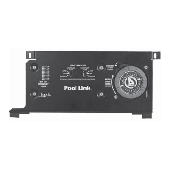
POOL LINK
Dual Timer Module
Control System
FOR YOUR SAFETY - This product must be installed and serviced by a pro fes sion al pool/
spa service technician. The procedures in this manual must be followed ex act ly. Failure to
follow warning notices and instructions may result in property damage, serious injury, or
death.
WARNING
Advertisement
Table of Contents

Related Manuals for Jandy POOL LINK


Summary of Contents for Jandy POOL LINK
- Page 1 Installation Data Installation Man u al POOL LINK Dual Timer Module Control System WARNING FOR YOUR SAFETY - This product must be installed and serviced by a pro fes sion al pool/ spa service technician. The procedures in this manual must be followed ex act ly. Failure to follow warning notices and instructions may result in property damage, serious injury, or death.
-
Page 3: Table Of Contents
3.3.1 System Power ....... 8 Two-Speed Filter Pump Operation . 13 3.3.2 3HP (Standard) Relays ....8 Heater Cool Down ......13 3.3.3 Bonding the Pool Link ....8 Freeze Protection ......13 Low Voltage Wiring ..... 10 3.4.1 Wire Relays to Printed Circuit Board ........ -
Page 4: Section 1. Important Safety Instructions
Page 4 Important Safety Instructions Section 1. READ AND FOLLOW ALL INSTRUCTIONS Lire la notice technique. All electrical work must be performed by a licensed electrician and conform to all national, state, and local codes. When installing and using this electrical equipment, basic safety precautions should always be followed, including the following: DANGER To reduce the risk of injury, do not remove the suction fittings of your spa or hot tub. - Page 5 Page 5 WARNING People with infectious diseases should not use a spa or hot tub. To avoid injury, exercise care when entering or exiting the spa or hot tub. Do not use drugs or alcohol before or during the use of a spa or hot tub to avoid unconsciousness and possible drowning.
-
Page 6: Section 2. System Overview
Page 6 Section 2. System Overview Package Contents Pool Link Control System Sub-Assemblies Power Centers (required and sold separately) 6613AP and 6614AP PureLink 6613 Standard Power Center 6614 Sub-Panel Power Center Sub-Panel Power Center (with (with mounting brackets) (with mounting brackets) mounting brackets) (6614AP shown). -
Page 7: System Component Specifi Cations And Dimensions
High voltage - 25 A; 3HP @ 240 VAC 1½ HP @ 120 VAC 1500 Watts Incandescent Low Voltage - Class Two, 1 A @ 24 VAC Service Switch All Circuits (located at Power Center) Dimensions Pool Link Control System 5½" 3" 2½" 2" 5" 10½"... -
Page 8: Section 3. Installation
Each piece of equipment requires its own high voltage relay. NOTE The Pool Link is not to be considered as Connect 120 volts to the transformer and Pool suitable for use as Service Equipment. - Page 9 Page 9 Transformer Transformer To "Motor" Terminals of Filter Time Clock To "Motor" (See Terminals Figure 6) of Filter Time Clock (See Figure 6) Wire nut to White 120 VAC power Black Earth Ground Neutral Black White Ground To 120 VAC Earth Ground From Main Breaker...
-
Page 10: Low Voltage Wiring
Connect two 18-gauge wires, designed for use in hot environments, to terminals 5 and 6 on the print- For the Pool Link, plug the in-floor cleaning ed circuit board as shown in Figure 6. Run the two system JVA into P6 (refer to Figure 6). Note: The... -
Page 11: Connect Freeze Protection Sensor To Printed Circuit Board
Sensor 3 and 4) Cleaning System or Series with Transformer Thermostat Water Feature Figure 6. Pool Link Wiring Diagram Single - Speed Filter Diode is stored T o 24 VAC Pump and Pool Cleaner here for future Power Supply use. -
Page 12: Connect System Power To Printed Circuit Board
P5 on the back of the Control System PCB (see Figure 8). Mount the Bezel to the Control System using the screws provided. 24 VAC Power Plug Connection Figure 8. Pool Link Control Panel (Back View) -
Page 13: Section 4. System Startup
Page 13 Section 4. System Startup Freeze Protection When freeze conditions exist, the filter pump will Set Time Clocks and Test Equipment turn on and run until the time clock duration is reached. If freeze conditions still exist after the Follow the instructions on the faceplate to set time has passed, the pump will remain on. - Page 14 Page 14 Notes...
- Page 15 Page 15 Notes...
-
Page 16: Warranty
DE grids, or cartridge elements; or damage caused by running the pump with insufficient quantities of water. LIMITATION OF LIABILITY: This is the only warranty given by Jandy Pool Products, Inc. No one is authorized to make any other warranties on behalf of Jandy Pool Products, Inc. THIS WARRANTY IS IN LIEU OF ALL OTHER WARRANTIES, EXPRESSED OR IMPLIED, INCLUDING BUT NOT LIMITED TO ANY IMPLIED WARRANTIES OF FITNESS FOR A PARTICULAR PURPOSE AND MERCHANTABILITY.
Need help?
Do you have a question about the POOL LINK and is the answer not in the manual?
Questions and answers