Table of Contents
Advertisement
Quick Links
OnSite 1052 &1063 Series
Metro-Optical Transport
Access Nodes
Getting Started Guide
Important
This is a Class A device and is not intended for use in a residential environment.
Sales Office:
+1 (301) 975-1000
Technical Support:
+1 (301) 975-1007
E-mail:
support@patton.com
WWW:
www.patton.com
Part Number: 07MOS10xx-GS, Rev. B
Revised: October 25, 2010
Advertisement
Table of Contents

Related Manuals for Patton electronics OnSite 07MOS10xx-GS


Summary of Contents for Patton electronics OnSite 07MOS10xx-GS
- Page 1 OnSite 1052 &1063 Series Metro-Optical Transport Access Nodes Getting Started Guide Important This is a Class A device and is not intended for use in a residential environment. Sales Office: +1 (301) 975-1000 Technical Support: +1 (301) 975-1007 E-mail: support@patton.com WWW: www.patton.com Part Number: 07MOS10xx-GS, Rev.
- Page 2 Patton Electronics Company, Inc. 7622 Rickenbacker Drive Gaithersburg, MD 20879 USA Tel: +1 (301) 975-1000 Fax: +1 (301) 869-9293 Support: +1 (301) 975-1007 Web: www.patton.com E-mail: support@patton.com Copyright © 2010, Patton Electronics Company. All rights reserved. The information in this document is subject to change without notice. Patton Electronics assumes no liability for errors that may appear in this document.
-
Page 3: Summary Table Of Contents
Summary Table of Contents Product Overview... 14 Application Overview ... 18 Installation Overview ... 23 System Management Access... 39 Contacting Patton for assistance Compliance information ... 56 Specifications ... 58 Terms and Acronyms ... 63 ... 53... -
Page 4: Table Of Contents
Table of Contents Summary Table of Contents Table of Contents ... 4 List of Figures ... 7 List of Tables ... 8 About this guide ... 9 Audience... 9 Structure... 10 Precautions ... 10 Safety when working with electricity Optical Safety ...12 Fiber-Optic Ports ...12... - Page 5 OnSite Series Getting Started Guide Mounting the Chassis to an ETSI Rack Mounting the Chassis on the Wall Installing the Chassis Ground Connection Connecting Power to the OS-10 System Connecting AC Power to the OS-10 System Powering On the OS-10 System with AC Power Connecting DC Power to the OS-10 System Wiring Procedure for DC Input Power Checking the OS-10 System Installation...
- Page 6 OnSite Series Getting Started Guide Expansion Modules ...59 Configuration & Port Capacity for 2 Expansion Slots Protection ...59 Bandwidth Connectivity and Provisioning Timing & Synchronization System Access ...59 Operations ...60 Management ...60 Packet Intelligence ...60 Dimensions ...60 Weight ...60 Cooling ...60 Mounting ...60...
-
Page 7: List Of Figures
List of Figures OnSite Model 1052 ..............15 OnSite Model 1063 . -
Page 8: List Of Tables
List of Tables General conventions ..............13 Mouse conventions . -
Page 9: About This Guide
About this guide This guide describes how to install a Patton OnSite Series Model 1052 and1063 Metro-Optical Transport Access Node. For detailed configuration and management instructions, refer to the OnSite 1052 & 1063 Series Administrator’s Reference Guide, which is located on the CD-ROM that came with your unit and at www.pat- ton.com. -
Page 10: Structure
OnSite Series Getting Started Guide Structure This guide contains the following chapters and appendices: • Chapter 1 describes the OnSite Series Metro-Optical Transport Access Nodes • Chapter 2 describes typical applications for the OS-10 series • Chapter 3 describes instructions for installing the OS-10 •... -
Page 11: Safety When Working With Electricity
OnSite Series Getting Started Guide Safety when working with electricity • Do not open the device when the power cord is connected. For systems without a power switch and without an external power adapter, line volt- ages are present within the device when the power cord is connected. •... -
Page 12: Optical Safety
OnSite Series Getting Started Guide Electrostatic Discharge (ESD) can damage equipment and impair electrical cir- cuitry. It occurs when electronic printed circuit cards are improperly handled and can result in complete or intermittent failures. Do the following to prevent ESD: Always follow ESD prevention procedures when removing and replacing •... -
Page 13: Typographical Conventions Used In This Document
OnSite Series Getting Started Guide Typographical conventions used in this document This section describes the typographical conventions and terms used in this guide. General conventions The procedures described in this manual use the following text conventions: Convention Garamond blue type Futura bold type Italicized Futura type Futura type... -
Page 14: Product Overview
Chapter 1 Product Overview Chapter contents Introduction ...15 OnSite Platforms ...15... -
Page 15: Introduction
OnSite Series Getting Started Guide 1 • Product Overview Introduction The OnSite Series is family of ultra-compact, micro multi-service provisioning platforms ( MSPPs). The sup- ports flexible and economic delivery of time division multiplexing (TDM) and Ethernet-based packet data ser- vices over synchronous digital hierarchy (SDH) transport networks. -
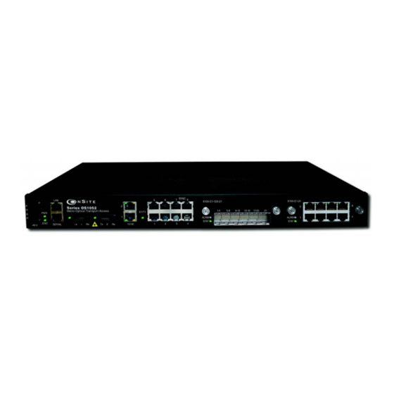
Page 16: Onsite Model 1063
OnSite Series Getting Started Guide Table 3. Base System Configuration for OnSite Platforms Type SDH Trunks Client Signals Management Expansion Slots The OS1052 and OS1063 systems have two expansion slots. The expansion slots support the insertion of the following modules for flexible configuration changes and capacity upgrades: •... -
Page 17: Os1052 Base System
OnSite Series Getting Started Guide Figure 2 shows the front panel of the OS1063 system. The OS1063 uses a future bus connector for access to the 21 E1 or T1 ports on the base system. When the system is equipped with two 21-port high-density E1 (HD-E1) expansion modules, the OS1063 provides access for up to 63 E1 ports. -
Page 18: Application Overview
Chapter 2 Application Overview Chapter contents OS1052 Application...19 OS1063 Application...21... -
Page 19: Os1052 Application
OnSite Series Getting Started Guide 2 • Application Overview OS1052 Application The advanced modular design of the Patton OnSite OS1052 provides unequaled flexibility in its class in terms of service offerings, capacity and functional upgrades. Figure 5. Typical OS1052 application OS1052 Application... -
Page 20: Os1052 Map + Modules
OnSite Series Getting Started Guide The base OS1052 system is configured with: • 2 STM-1 • 8 E1/T1 • 2 Ethernet • 10/100Base-TX Two expansion module slots allow increasing system capacity beyond the initial base configuration. Additional ports and features only require simple insertion of one of the many available types of TDM and packet data modules. -
Page 21: Os1063 Application
OnSite Series Getting Started Guide 2 • Application Overview OS1063 Application The advanced modular design of the Patton OnSite OS1063 provides unequaled flexibility in its class in terms of service offerings, capacity and functional upgrades. Figure 7. Typical OS1063 application OS1063 Application... -
Page 22: Os1063 Map + Modules
OnSite Series Getting Started Guide The base OS1063 system is configured with: • 2 STM-1 • 21 E1/T1 Two expansion module slots allow increasing system capacity beyond the initial base configuration. Additional ports and features only require simple insertion of one of the many available types of TDM and packet data modules. -
Page 23: Installation Overview
Chapter 3 Installation Overview Chapter contents Introduction ...24 Unpacking and Inspection...24 Site Preparation ...24 Site Environment ...25 Planning Your Site...25 Site Requirements ...25 Operating Environment Requirements Power Supply Requirements Distribution Rack Requirements Mechanical Recommendations for the Rack Protective Grounding for the Rack and Chassis Space Requirements for the Rack Securing the Rack ...28... -
Page 24: Introduction
OnSite Series Getting Started Guide Introduction This chapter provides the procedures for installing the OnSite OS-10 system. Unpacking and Inspection Do not unpack the OS-10 system until you are ready to install it. If the final installation site will not be ready for some time, keep the chassis in its shipping container to prevent accidental damage. -
Page 25: Site Environment
OnSite Series Getting Started Guide Site Environment The OS-10 system can be mounted in a rack or on a wall. The location of the chassis and layout of your equip- ment rack or wiring room are extremely important for proper system operation. Equipment that is too close together, ventilation that is inadequate, and panels that are inaccessible can make system maintenance difficult or cause system malfunctions and possible shutdowns. -
Page 26: Operating Environment Requirements
OnSite Series Getting Started Guide • Distribution rack requirements The following sections provide further details for each area. Operating Environment Requirements You need to verify that your site meets all environmental and safety requirements. During the early planning stages of installing or modifying your network, it is important that you develop a thorough understanding of the regulations that pertain to your location and industry. -
Page 27: Power Supply Requirements
OnSite Series Getting Started Guide Power Supply Requirements To operate your OS-10 equipment safely, follow these requirements: • Ensure that your power supply meets the site power requirements of the equipment to be installed. • Check the power at your site to ensure that you are receiving “clean” power (free of spikes and noise). Install a power conditioner, if necessary. -
Page 28: Mechanical Recommendations For The Rack
OnSite Series Getting Started Guide Mechanical Recommendations for the Rack The following information will help you plan your equipment rack configuration: • Use a rack made of steel or aluminum. • Install equipment in the lower half of the rack first to avoid making the rack top heavy. •... -
Page 29: Tools And Equipment For Installation And Maintenance
OnSite Series Getting Started Guide Tools and Equipment for Installation and Maintenance You need the following tools and equipment to install or upgrade the OS-10 system and its components: • ESD-preventive cord and wrist strap (when working with modular components or expansion cards) •... -
Page 30: Mounting The Chassis To An Etsi Rack
OnSite Series Getting Started Guide Note Take care to load the rack so that it is not top heavy. Note Do not cover vents that would restrict airflow. Leave a minimum of a half-rack space above and below the OS-10 system for adequate ven- tilation. -
Page 31: Mounting The Os-10 System In An Etsi 300-Mm Rack
OnSite Series Getting Started Guide Note Do not cover vents that would restrict airflow. Leave a minimum of a half-rack space above and below the OS-10 system for adequate ven- tilation. 3. Secure the chassis using four 12-24 x 3/4-inch screws (two screws for each side) through the elongated holes in the L bracket nearest to the chassis and to the threaded holes in the mounting post. -
Page 32: Mounting The Chassis On The Wall
OnSite Series Getting Started Guide Mounting the Chassis on the Wall Note When choosing a wall-mounting location, consider the cable limita- tions and the wall structure. Use the four L brackets provided for rack mounting to mount the chassis on a wall. The brackets provide the most stable installation for the chassis. -
Page 33: Installing The Chassis Ground Connection
OnSite Series Getting Started Guide Installing the Chassis Ground Connection The OS-10 system chassis requires a reliable earth ground connection. You must connect the chassis to a reli- able earth ground. The ground wire must be installed in accordance with local electrical safety standards. Grounding Standard EN/IEC 60950 NEBS... -
Page 34: Connecting Ac Power To The Os-10 System
OnSite Series Getting Started Guide Note The DC-to-DC converter has dual power inputs (A and B power). The system continues to operate normally if either the A or B power input fails. The system uses natural convection for heat dissipation (that is, it does not use fans). The absence of fans increases system reliability and eliminates periodic maintenance visits for fan filter vides the maximum power consumption figures for the OS-10 system under normal operating conditions. -
Page 35: Powering On The Os-10 System With Ac Power
OnSite Series Getting Started Guide Powering On the OS-10 System with AC Power To power on the OS-10 system using AC power, follow these steps: 1. Connect the AC power cable to the OS-10 system and then to the wall outlet. 2. -
Page 36: Wiring The Os-10 System For Dc Power
OnSite Series Getting Started Guide Figure 13. Wiring the OS-10 System for DC Power 1. Choose an available circuit from a DC power source and identify both the positive and negative leads for this circuit. Note The DC power source may be a DC circuit breaker or an AC-to-DC power rectifier. - Page 37 OnSite Series Getting Started Guide The ground wire should always be connected first and discon- nected last. CAUTION 5. Connect the positive lead of the circuit to the return direction for “A” power on the OS-10 system termi- nal block. See wiring 2-A in Figure 7. Note The terminal block indicates the return direction for “A”...
-
Page 38: Checking The Os-10 System Installation
OnSite Series Getting Started Guide 9. Connect the negative lead of the circuit to the “B” power input lead on the OS-10 system terminal block. See wiring 3-B on figure 13 Note The terminal block indicates the “B” power lead by the letter B. This lead is third from the top on the OS-10 system terminal block. -
Page 39: System Management Access
Chapter 4 System Management Access Chapter contents Introduction ...40 General Overview...40 Ethernet LAN Management Port Serial Management Port ...42 Gaining Access to the System ...43 Access through the Serial Port Access through the Ethernet LAN Management Port Web-Based Management Interface Launching the GUI Application Autonomous Alarm Messages ...47... -
Page 40: Introduction
OnSite Series Getting Started Guide 4 • System Management Access Introduction This chapter provides the procedures for configuring and monitoring the local serial and LAN management (LM) ports, and the inband management channel (IMC) for remote management communications. The chap- ter also provides the procedures for configuring and using the Orderwire communications port (if the AUX port is factory-installed). -
Page 41: Ethernet Lan Management Port
OnSite Series Getting Started Guide Figure 15 provides a close-up view of the two management ports. The figure includes the location of the RJ-45 connector pins for both ports. Figure 16 shows the location of the signal pins on the RJ-45 plug. Figure 16. -
Page 42: Serial Management Port
OnSite Series Getting Started Guide Table 11 provides the pin assignments for the RJ-45 connector. Table 11. Pin Assignments for the Ethernet LAN Management Port Serial Management Port The physical connector for the RS-232 SERIAL management port is an RJ-45 connector. the pin assignments for the RJ-45 connector. -
Page 43: Gaining Access To The System
OnSite Series Getting Started Guide Gaining Access to the System There are two ways of gaining access to the system management functions. One way is through the SERIAL port and the command line interface (CLI). The other way is through the Ethernet LAN port and the web browser interface. -
Page 44: Access Through The Ethernet Lan Management Port
OnSite Series Getting Started Guide 8. Type the following CLI command to save the IP settings (address, net mask, and default gateway)for the Ethernet LAN management port to the system configuration file, and then press the Enter key: save config Note Saving the configuration is important to prevent the loss of the IP configuration data if a system reset or reboot occurs. -
Page 45: Web-Based Management Interface
OnSite Series Getting Started Guide “Web-Based Management Interface” features. Once you gain access to the system through the Ethernet LAN port, you may change the IP settings for the port for secure access in the future. 5. Refer to the OnSite Series Administrator’s Reference Guide, located on the CD that came with your unit and online at www.patton.com for instructions on how to change the IP settings for the Ethernet LAN port. -
Page 46: Web-Based Management Gui Frames
OnSite Series Getting Started Guide After successful completion of the login, the browser displays the OnSight DM splash screen from which you can select the language of your choice (English or Chinese, currently). After language selection, the browser displays the System Information page. The OnSight DM screen is divided into three frames, as shown in Figure Table 15 provides a description of each frame. -
Page 47: Autonomous Alarm Messages
OnSite Series Getting Started Guide Autonomous Alarm Messages You can configure the system to generate autonomous alarm messages that can be received and displayed by an SNMP-based network management system (NMS). By default, the system does not generate SNMP traps. To allow the generation of SNMP traps, you must first configure the IP address of the NMS host device or devices to which you wish to direct the traps. -
Page 48: Configuring An Authorized Onsight Nms Server
OnSite Series Getting Started Guide 4 • System Management Access To remove an existing SNMP trap receiver, follow these steps: 1. Select a trap receiver on the SNMP Trap Receivers page. 2. Click on Delete to remove the trap receiver. At this point, the system removes the trap receiver, and it is no longer displayed in the table. -
Page 49: Engineering Orderwire (Eow)
OnSite Series Getting Started Guide Engineering Orderwire (EOW) If the system is equipped with the factory-installed AUX (auxiliary) board, you can use AUX port 1 (AUX 1) for voice communications between two or more interconnected OnSite OS-10 Series systems. Figure 20 shows the location of EOW port (AUX 1) on the system. -
Page 50: Location Of Signal Pins On The Eow Port (Aux 1) Rj-11 Connector
OnSite Series Getting Started Guide To prevent electrical shock, never touch uninsulated wires or terminals when the phone line is plugged into the RJ-11 connector of the EOW port (AUX 1). WARNING Figure 21. Location of signal pins on the EOW port (AUX 1) RJ-11 connector The EOW port supports dual-tone multifrequency (DTMF) signaling to identify EOW stations within an OnSite OS-10 subnetwork. -
Page 51: Configuring The Engineering Orderwire (Eow) Function
OnSite Series Getting Started Guide Note In addition to supporting selective calling of EOW stations using the station ID, the EOW also supports a party-line function that allows calling and communicating with all EOW stations at once (party-line function) by dialing *000. 6. - Page 52 OnSite Series Getting Started Guide At this point, the called station begins to ring if another telephone set is connected to the EOW port of that station. Note To call and communicate with all EOW stations at once (party-line function), dial *000. To complete the call, simply place the telephone set in the on-hook position, like a regular analog phone.
-
Page 53: Contacting Patton For Assistance
Chapter 5 Contacting Patton for assistance Chapter contents Introduction ...54 Contact information...54 Warranty Service and Returned Merchandise Authorizations Warranty coverage ...54 Out-of-warranty service Returns for credit ...54 Return for credit policy RMA numbers ...55 Shipping instructions ...55 (RMAs)...54 ...54 ...55... -
Page 54: Introduction
OnSite Series Getting Started Guide Introduction This chapter contains the following information: • “Contact information”—describes how to contact Patton technical support for assistance. • “Warranty Service and Returned Merchandise Authorizations RAS warranty and obtaining a return merchandise authorization (RMA). Contact information Patton Electronics offers a wide array of free technical services. -
Page 55: Return For Credit Policy
OnSite Series Getting Started Guide Return for credit policy • Less than 30 days: No Charge. Your credit will be issued upon receipt and inspection of the equipment. • 30 to 120 days: We will add a 20% restocking charge (crediting your account with 80% of the purchase price). -
Page 56: A Compliance Information
Appendix A Compliance information Chapter contents Compliance ...57 ...57 Low-Voltage Directive (Safety) PSTN ...57 Declaration of Conformity ...57 Authorized European Representative ...57 ...57... -
Page 57: Compliance
OnSite Series Getting Started Guide Compliance • EN 55022 Class A • EN55024 Low-Voltage Directive (Safety) • IEC/EN60950-1 PSTN • This device is not intended nor approved for connection to the PSTN. Declaration of Conformity Patton Electronics, Inc declares that this device is in compliance with the essential requirements and other rel- evant provisions of Directive 2004/108/EC relating to electromagnetic compatibility and Directive 2006/95/EC relating to electrical equipment designed for use within certain voltage limits. -
Page 58: Specifications
Appendix B Specifications Chapter contents Model OS1052...59 Trunk Interfaces ...59 Client Interfaces ...59 Expansion Modules ...59 Configuration & Port Capacity for 2 Expansion Slots Protection ...59 Bandwidth Connectivity and Provisioning Timing & Synchronization System Access ...59 Operations ...60 Management ...60 Packet Intelligence ...60 Dimensions... -
Page 59: Model Os1052
OnSite Series Getting Started Guide B • Specifications Model OS1052 Trunk Interfaces STM-1: G.707, G.783 Optics: G.957 S-1.1, L-1.1 and L-1.2 options Client Interfaces E1: G.703, 75-ohm and 120-ohm options T1: G.703, 100-ohm Ethernet 10/100Base-TX: 802.3u Expansion Modules SDH: STM-1 optical (2 ports) • STM-1 electrical (2 ports) PDH: E1 (21 ports) •... -
Page 60: Operations
OnSite Series Getting Started Guide B • Specifications Operations Local and remote software download and upgrade (FTP/TFTP) Loopbacks: facility and terminal ALS (automatic laser shutdown): G.958 Alarm Contacts (optional) Orderwire: 2-wire interface using E1 or E2 byte (optional) Management Web-based GUI management interface SNMP v1/v2 Packet Intelligence Ethernet MAC: 802.3... -
Page 61: Model Os1063
OnSite Series Getting Started Guide B • Specifications Model OS1063 Trunk Interfaces STM-1: G.707, G.783 Optics: G.957 S-1.1, L-1.1 and L-1.2 options Client Interfaces E1: G.703, 75-ohm and 120-ohm options T1: G.703, 100-ohm Ethernet 10/100Base-TX: 802.3u Expansion Modules SDH: STM-1 optical (2 ports) • STM-1 electrical (2 ports) PDH: E1 (21 ports) •... -
Page 62: Operations
OnSite Series Getting Started Guide B • Specifications Operations Local and remote software download and upgrade (FTP/TFTP) Loopbacks: facility and terminal ALS (automatic laser shutdown): G.958 Alarm Contacts (optional) Orderwire: 2-wire interface using E1 or E2 byte (optional) Management Web-based GUI management interface SNMP v1/v2 Packet Intelligence Ethernet MAC: 802.3... -
Page 63: Terms And Acronyms
Appendix C Terms and Acronyms Chapter contents Abbreviations ...64... -
Page 64: Abbreviations
OnSite Series Getting Started Guide Abbreviations Abbreviation B3ZS B8ZS cHEC CSU/DSU C-Tag ETSI HDB3 HTTP Abbreviations Meaning Alarm Indication Signal Alternate Mark Inversion Administrative Unit Auxiliary (port) Bit Interleaved Parity Background Block Error Bit Error Rate Bipolar Violation Bipolar with 3-zero Substitution Bipolar with 8-zero Substitution core Header Error Check Command Line Interface... - Page 65 OnSite Series Getting Started Guide Abbreviation LCAS NEBS POST RSOH SNMP S-Tag STM-1 Abbreviations Meaning Link Capacity Adjustment Scheme Loss of Frame Delineation Loss of Frame Loss of Pointer Low-order Path Multiplex Section Network Equipment Building System National Electric Code Private Branch Exchange Personal Computer Plesiochronous Digital Hierarchy...
- Page 66 OnSite Series Getting Started Guide Abbreviation Abbreviations Meaning Time Division Multiplexing Telecommunications Industry Association Trace Identifier Mismatch Telecommunications Network Voltage Termination Point Tributary Unit Tributary Unit Group Unavailable Seconds C • Terms and Acronyms...