Table of Contents
Advertisement
Quick Links
Copyright © 2006
Patton Electronics Company
All Rights Reserved.
USER
MANUAL
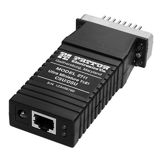
MODEL 2711 Series
MicroLink-T1™
T1/Fractional T1 CSU/DSU
Part# 07M2711-UM
Doc# 08606U2-001,
Rev. D
Revised 10/26/06
C E R T I F I E D
An ISO-9001
Certified Company
SALES OFFICE
(301) 975-1000
TECHNICAL SUPPORT
(301) 975-1007
http://www.patton.com
Advertisement
Table of Contents

Summary of Contents for Patton electronics Model 2711
- Page 1 Copyright © 2006 Patton Electronics Company All Rights Reserved. USER MANUAL MODEL 2711 Series MicroLink-T1™ T1/Fractional T1 CSU/DSU Part# 07M2711-UM SALES OFFICE Doc# 08606U2-001, (301) 975-1000 Rev. D TECHNICAL SUPPORT Revised 10/26/06 C E R T I F I E D (301) 975-1007 http://www.patton.com...
-
Page 2: Table Of Contents
Patton Electronics Technical Support at (301) 975-1007. 1.1 WARRANTY STATEMENT Patton Electronics warrants all Model 2711 Series components to be free from defects, and will—at our option—repair or replace the product should it fail within one year from the first date of shipment.This warranty is limited to defects in workmanship or materi-... -
Page 3: Radio And Tv Interference
FCC registration number. You may be requested to provide this information to your telephone company. your service if they believe that the Model 2711 may cause harm to the telephone network. Whenever possible the telephone company will attempt to notify you in advance. -
Page 4: Service
48S jack on the rear of the unit. Seven easy-to-read LED indicators monitor data, network, test sig- nals, and proper setup. Model 2711 is also available for 120 VAC or 100-240 Universal Interface (UI), or even DTE Interface power opera-... -
Page 5: Supported Applications
2.3.2 The 2711 as a High-Speed Short Range Modem The Model 2711 Series can also be installed into high-speed cam- pus applications. In this application, a pair of Model 2711 Series units operate as short range modems (See below). Bridge/Router... -
Page 6: Dip Switches Sw1 - Sw8
Clocking Mode Network Internal Network Internal External These switches set the DTE date rate. Each setting represents MODEL 2711 DTE DATA RATE DTE Data Rate 1544 kbps (unframed) 56/64 kbps (n=1) 112/128 kbps (n=2) 168/192 kbps (n=3) 224/256 kbps (n=4) - Page 7 Switches SW1.1 SW1.2, SW1.3, SW 2.7 & SW2.8 These switches set the starting channel. The starting channel is the first channel that carries valid data. This channel can be set to any value between 1 and 24. If the starting channel is other than 1, then the maximum possible bandwidth will be less than 1536 kbps.
- Page 8 Switch SW2.3 Line Framing This switch is used to set the frame. There are three framing modes available in the Model 2711 Series: ESF, D4 and Unframed. When SW1.8~SW1.4 are turned off, the unit is set to unframed opera- tion, and SW2.3 is ignored. Otherwise, SW2.3 is used to set the frame to either ESF or D4.
-
Page 9: Installation
DC Power Supply The 36-60 VDC DC to DC adapter is supplied with the DC version of the Model 2711. The black and red leads plug into a DC source (nominal 48VDC) and the barrel power connector plugs into the barrel power supply jack on the 2711. -
Page 10: Central Office Loops
(Alarm) glows red to indicate that one of several alarm conditions exist. These con- ditions may be local alarms or remote alarm conditions. Alarms may occur due to: • Loss of Synchronization • Loss of Frame • AIS (Blue Alarm) •... -
Page 11: Appendix A - Specifications
3.5”L x 2.1”W x 0.78”H (9.0 x 5.3 x 1.9 APPENDIX B PATTON MODEL 2711 SERIES CABLE RECOMMENDATIONS The Patton Model 2711 Series operates at frequencies of 20kHz or less and has been performance tested by Patton technicians using twisted-pair cable with the following characteristics:... - Page 12 APPENDIX C PATTON MODEL 2711 SERIES FACTORY REPLACEMENT PARTS AND ACCESSORIES Patton Model # Description 2711/CM/120 ...T1 Nx64 CSU/DSU(M/34 Male, 120VAC) 2711/CM/UI ...T1 CSU/DSU (V.35 M/34 Male, UI) 07M2711...User Manual APPENDIX D PATTON MODEL 2711 SERIES INTERFACE PIN ASSIGNMENT RJ-48C T1 (DS0) Network Interface...
-
Page 13: Appendix E - Power Supply Interface
APPENDIX D (continued) PATTON MODEL 2711 SERIES INTERFACE PIN ASSIGNMENT M/34 Connector, Terminal Interface Pin # Signal GND (Earth Ground/Shield) SGND (Signal Ground) CTS (DCE Source) DSR (DCE Source, Always On) CD (DCE Source) LL (Local Loop, DTE Source) TM (Test Mode Indicators, DCE Source)


Need help?
Do you have a question about the Model 2711 and is the answer not in the manual?
Questions and answers