Table of Contents
Advertisement
SIMATIC NET
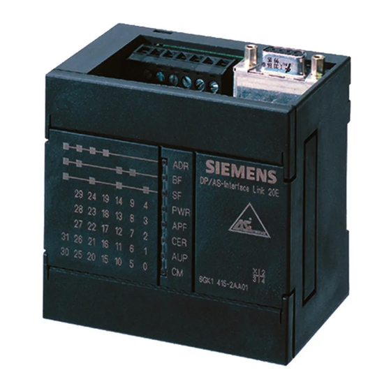
DP/AS-Interface Link 20E
Manual
Release 11/2002
C79000-G8976-C138–04
Industrial Ethernet
PROFIBUS
AS–Interface
Preface, Contents
Technical Description, Installation
Instructions, Operation
Data Exchange between DP
Master and AS-i Slave
Using the Command Interface
Slave Diagnostics
Eliminating Problems /
Error Displays
Appendix
AS-Interface
Protocol Implementation
Conformance Statements
Structure of the PROFIBUS
Parameter Assignment and
Configuration Frame
AS-Interface
References
Note on the CE Mark
Glossary
Index
1
2
3
4
5
A
B
C
D
E
Advertisement
Table of Contents

Related Manuals for Siemens DP/AS-Interface Link 20E


Summary of Contents for Siemens DP/AS-Interface Link 20E
- Page 1 Preface, Contents Technical Description, Installation Instructions, Operation SIMATIC NET Data Exchange between DP Master and AS-i Slave DP/AS-Interface Link 20E Using the Command Interface Slave Diagnostics Manual Eliminating Problems / Error Displays Appendix AS-Interface Protocol Implementation Conformance Statements Structure of the PROFIBUS...
- Page 2 Note highlights important information on the product, using the product, or part of the documentation that is of particular importance and that will be of benefit to the user. DP/AS-Interface Link 20E Release 11/2002 C79000-G8976-C138–04...
- Page 3 Siemens. Before you use the supplied sample programs or programs you have written yourself, make certain that no injury to persons nor damage to equipment can result in your plant or process. DP/AS-Interface Link 20E Release 11/2002 C79000-G8976-C138–04...
- Page 4 You will find the ordering data for this documentation in the relevant catalogs or contact your local Siemens office. Copyright E Siemens AG 2001–2002 All rights reserved Disclaimer of Liability The reproduction, transmission or use of this document or its contents is not We have checked the contents of this manual for agreement with the hard- permitted without express written authority.
- Page 5 Preface Purpose of the Manual This manual supports you when using the DP/AS-Interface Link 20E module, shortened to DP/AS-i Link 20E in the following chapters. It contains information about how PROFIBUS DP masters can address AS-i actuators and AS-i sensors via this module.
- Page 6 Preface DP/AS-Interface Link 20E Release 11/2002 C79000-G8976-C138–04...
-
Page 7: Table Of Contents
......... . . Command Interface of the DP/AS-Interface Link 20E . - Page 8 Error Displays/Remedying Errors ........DP/AS-Interface Link 20E Release 11/2002...
-
Page 9: Dp/As-Interface Link 20E Release 11/2002
........DP/AS-Interface Link 20E Release 11/2002 C79000-G8976-C138–04... - Page 10 Contents DP/AS-Interface Link 20E Release 11/2002 C79000-G8976-C138–04...
-
Page 11: Technical Description, Installation Instructions, Operation
Technical Description, Installation Instructions, Operation This chapter explains the performance, installation and basic functions of the master module DP/AS-Interface Link 20E module (DP/AS-i Link 20E). You will learn the following: S How to install the DP/AS-i Link 20E module S The display and control elements of the DP/AS-i Link 20E module... -
Page 12: General Notes On Operation - Safety Warnings
S VDE 0805 = EN60950 = IEC 950 (as safety extra-low voltage SELV) or S VDE 0106 Part 101 Note The DP/AS-i Link 20E module can be configured, installed and started up independent of the PROFIBUS installation. DP/AS-Interface Link 20E Release 11/2002 C79000-G8976-C138–04... -
Page 13: Application Of The Module
– Standard Slaves / AS–i Analog Slaves – Slaves with the extended addressing mode Wider networking via PROFIBUS DP DP/AS-Interface Link 20E 6GK7 1415 2AA0 DP/AS-Interface Link 20E Active module Passive module (with slave ASIC) (without slave ASIC) AS-i power supply... -
Page 14: Release
Commands complying with the AS-i master specification M1e are implemented with the read_record/write_record (record 2) services. Components of the Product The product DP/AS-i Link 20E includes the following components: S DP/AS-i Link 20E S Product information for the DP/AS-i Link 20E DP/AS-Interface Link 20E Release 11/2002 C79000-G8976-C138–04... -
Page 15: Technical Data Of The Module
Transportation and storage temperature –40°C to +70°C Relative humidity max. 95% at +25°C Construction Type of protection IP 20 Dimensions (W x H x D) in mm 90 x 80 x 62 Weight approx. 200 g DP/AS-Interface Link 20E Release 11/2002 C79000-G8976-C138–04... -
Page 16: Installing The Module
The standard rail can also be installed vertically. Due to the reduced convection, the maximum permitted ambient temperature is reduced to 45°C. Fit a grounding clip to the standard rail below the DP/AS-i Link 20E to prevent it slipping down on the standard rail. DP/AS-Interface Link 20E Release 11/2002 C79000-G8976-C138–04... -
Page 17: Front Panel - Access To All Functions
DP/AS-i Link 20E module. In operation, the connection and control elements are protected by a front cover. Connection Elements (front cover open) PROFIBUS DP DP/AS-Interface Link 20E Group Display – 3 LEDs Slave Display – 5 LEDs... -
Page 18: Connection Elements
The DP/AS-i Link 20E module is supplied with power entirely from the AS-Interface. The current consumption from the AS-Interface is 200 mA. AS-i cables Functional ground Connections not used – – PROFIBUS DP Figure 1-3 Connection of the AS-i Cable DP/AS-Interface Link 20E Release 11/2002 C79000-G8976-C138–04... - Page 19 When laying and installing the PROFIBUS DP cable and the bus connector, follow the instructions in /5/. To connect to PROFIBUS DP, bus connectors are available with cable outlets at different angles (0°, 30° and 90°). Once again, follow the instructions in /5/. DP/AS-Interface Link 20E Release 11/2002 C79000-G8976-C138–04...
-
Page 20: Display And Control Elements
Í Í È È È Static display: AS-i standard slaves and A slaves Flashing display: B slaves Í Í È È È Key: red or off green green or off Í Í È È È DP/AS-Interface Link 20E Release 11/2002 C79000-G8976-C138–04... -
Page 21: Status Display
While pressing the SET button, the DP/AS-i Link 20E module cannot currently make the required mode change (for example a slave exists with address 0). PWR (green) The LED is lit when the DP/AS-Interface Link 20E is supplied with power. APF (red) AS-i Power Fail This indicates that the voltage supplied to the AS-i cable by the AS-i power supply unit is too low. - Page 22 DP/AS-i Link 20E module. In the configuration mode, the DP/AS-i Link 20E module activates all connected AS-i slaves and exchanges data with them. For more information about the configuration mode, refer to Section 1.8. DP/AS-Interface Link 20E Release 11/2002 C79000-G8976-C138–04...
-
Page 23: Slave Display For As-I Slaves
S If the DP/AS-i Link 20E module is in the protected mode, all active AS-i slaves are displayed. In the protected mode, failed or existing but unconfigured AS-i slaves are indicated by the corresponding LED flashing. DP/AS-Interface Link 20E Release 11/2002 C79000-G8976-C138–04... - Page 24 From the display you can obtain the following information: S The group LEDs indicate the second group of five. S Within this group, the active AS-i slaves 6 and 8 are displayed by the lower five LEDs. DP/AS-Interface Link 20E Release 11/2002 C79000-G8976-C138–04...
-
Page 25: Displaying And Setting The Profibus Address
(LED off). The display then jumps to the “SF” LED (next address bit of the PROFIBUS address). 5. By following the steps outlined above, you can now set or reset each of the individual bits of the PROFIBUS address. DP/AS-Interface Link 20E Release 11/2002 C79000-G8976-C138–04... - Page 26 The highest address that can be set is address 126. Remember that address 126 is reserved on PROFIBUS for special functions (address assignment). For data exchange with a DP master, you can use addresses 1 to 125. DP/AS-Interface Link 20E Release 11/2002 C79000-G8976-C138–04...
-
Page 27: Configuring The As-Interface With The Set Button (Button Configuration)
SET button. Any AS-i slaves active at this point are therefore configured. The AS-i slave information shown below is then stored in non-volatile memory on the DP/AS-Interface Link 20E module: S the addresses... - Page 28 Technical Description, Installation Instructions, Operation Protected Mode If the DP/AS-Interface Link 20E is in the protected mode, it only exchanges data with slaves that are “configured”. In this sense, “configured” means that the slave addresses stored on the DP/AS-Interface Link 20E and the configuration data stored on the DP/AS-Interface Link 20E match the values of the existing AS-i slaves.
- Page 29 Changing from the configuration mode to the protected mode is only possible when there is no AS-i slave with address 0 connected to the AS-Interface. If a slave 0 is connected, the “SF” LED lights up when the SET button is pressed. DP/AS-Interface Link 20E Release 11/2002 C79000-G8976-C138–04...
-
Page 30: Configuring The Dp/As-I Link 20E As A Dp Slave On The Dp Master
S The use of the GSD file S The entries to be made in the configuration tool of the DP master S Configuration of a DP master from the SIMATIC S7 device range in STEP 7. DP/AS-Interface Link 20E Release 11/2002 C79000-G8976-C138–04... -
Page 31: General Procedure
S7 with DP STEP 7 up to Version 5 Import GSD file and set DPV0 or DPV1 can be attachment via CP with SP2 S7 mode selected (see Section 342-5 and CP 443-5 1.9.2) DP/AS-Interface Link 20E Release 11/2002 C79000-G8976-C138–04... - Page 32 Interface Center Fürth at the telephone number +49 911 737972. The GSD file can also be downloaded from the Internet at http://www.ad.siemens.de/csinfo/ (under “All Downloads...”). BMP File (bitmap) To allow graphic representation of the DP/AS-i Link 20E, some configuration tools, for example STEP 7, use bitmap files.
-
Page 33: Importing A Gsd File
DP master and when the master is configured with STEP7 V5.0 SP2 or with an earlier version. Caution If you use a DPV0 master, you must leave the “DPV1 disable” setting! Otherwise the I/O transfer may be deactivated if AS-i errors occur. DP/AS-Interface Link 20E Release 11/2002 C79000-G8976-C138–04... - Page 34 DP/AS-i Link 20E module when you configure the DP master. The structure of the parameter assignment and configuration frame for the DP/AS-i Link 20E module is explained in Appendix C. DP/AS-Interface Link 20E Release 11/2002 C79000-G8976-C138–04...
-
Page 35: Configuration In Step 7 - Basic Configuration
After you have inserted the DP/AS-i Link 20E as a DP slave, there are still no AS-i slaves to be seen in the detailed view of the station window. With this default setting, the configuration rules of “configuration by button” apply initially (see Section 1.8 ). DP/AS-Interface Link 20E Release 11/2002 C79000-G8976-C138–04... - Page 36 Start addresses: The settings must be identical for inputs and outputs. Reserved length: Pack: As default, 32 bytes are The address utilization is optimized; all reserved gaps are eliminated During packing, the area is optimized DP/AS-Interface Link 20E Release 11/2002 C79000-G8976-C138–04...
- Page 37 If you replace an AS-i slave (due to a fault), the addresses are pro- grammed automatically. If you do not require this functiona- lity, for example for safety reasons, the option can be deselected here. DP/AS-Interface Link 20E Release 11/2002 C79000-G8976-C138–04...
-
Page 38: Configuring In Step 7 - Slave Configuration
This specifies the addresses of the AS-i slaves. Notice If you define the AS–I slave configuration in STEP 7, any button configuration on the DP/AS–I Link 20E is overwritten during the DP startup. DP/AS-Interface Link 20E Release 11/2002 C79000-G8976-C138–04... - Page 39 By configuring the properties of the AS-i slaves, you can do the following: S Store general information for the AS-i slaves S Enter configuration data of the AS-i slaves S Specify the I/O configuration S Specify I/O address areas DP/AS-Interface Link 20E Release 11/2002 C79000-G8976-C138–04...
- Page 40 Depending on the I/O configuration, you can specify the address area for input/output data here. 1 For AS-i slaves that do not support the ID1/ID2 codes, enter the values F DP/AS-Interface Link 20E Release 11/2002 C79000-G8976-C138–04...
- Page 41 Here, for example: ID Code: 3h ID1: Fh (is not evaluated)1 ID2: 5h = 2-channel analog slave 1 For AS-i slaves that do not support the ID1/ID2 codes, enter the values F DP/AS-Interface Link 20E Release 11/2002 C79000-G8976-C138–04...
- Page 42 With A/B slaves, only three bits are available! Bit 4 is required for the address changeover. Depending on the I/O configuration, you can specify the address area for input/output data here. DP/AS-Interface Link 20E Release 11/2002 C79000-G8976-C138–04...
-
Page 43: Upload Actual Configuration
Tip: To use this function simply for information despite an existing defined configuration in STEP 7, you can upload the actual configuration, check it and then click the “Cancel” button in the dialog. DP/AS-Interface Link 20E Release 11/2002 C79000-G8976-C138–04... -
Page 44: Transmission Rate On Profibus
Transmission Rate on PROFIBUS The DP/AS-i Link 20E supports the following transmission rates on PROFIBUS 9.6 Kbps 19.2 Kbps 45.45 Kbps 93.75 Kbps 187.5 Kbps 500 Kbps 1.5 Mbps 3 Mbps 6 Mbps 12 Mbps DP/AS-Interface Link 20E Release 11/2002 C79000-G8976-C138–04... -
Page 45: Data Exchange Between The Dp Master And As-I Slave
AS-i Slave This chapter contains the information you require to access the AS-Interface from the DP master via the DP/AS-Interface Link 20E (DP/AS-i Link 20E) The chapter explains the transfer of the following: S Binary values using the cyclic DP services... -
Page 46: Preparation For Operation - An Overview
–> Section 2.3 Write a user program with analog value access for the DP master –> Section 2.4 For example, create a program for an S7 CPU with a DP interface in LAD/CSF/STL Putting into operation DP/AS-Interface Link 20E Release 11/2002 C79000-G8976-C138–04... -
Page 47: How The Interfaces Work
S Acyclic services of PROFIBUS-DP V1 In the remainder of this description, these services are known as read_record and write_record. They are used for the following: – The transfer of analog values – To operate the command interface DP/AS-Interface Link 20E Release 11/2002 C79000-G8976-C138–04... -
Page 48: Transferring As-I Binary Values
Addressing these bytes within the DP master (in the user program etc.) depends on the PROFIBUS DP master being used. You will find examples of this below. For more detailed information, refer to /3/ and the manuals for your PROFIBUS DP master. DP/AS-Interface Link 20E Release 11/2002 C79000-G8976-C138–04... -
Page 49: Addressing As-I Slaves
Slave 29 or 29A m+15 Slave 30 or 30A Slave 31 or 31A m+16 reserved Slave 1B m+17 Slave 2B Slave 3B m+18 Slave 4B Slave 5B m+19 Slave 6B Slave 7B m+20 Slave 8B Slave 9B DP/AS-Interface Link 20E Release 11/2002 C79000-G8976-C138–04... - Page 50 S The input nibbles of these AS-i slaves are set to the value “0” by the DP/AS-i Link 20E; S The output nibbles of these AS-i slaves are ignored by the DP/AS-i Link 20E; How to access AS-i analog slaves is described in Section 2.4. DP/AS-Interface Link 20E Release 11/2002 C79000-G8976-C138–04...
- Page 51 The assignment of the AS-i terminals of the AS-i bus modules to the data bits of the input/output bytes is shown below based on the example of slave number 3: Bit no. Input byte 1 Terminal 2 on the AS-i bus module Terminal 1 on the AS-i bus module DP/AS-Interface Link 20E Release 11/2002 C79000-G8976-C138–04...
- Page 52 Data Exchange Between the DP Master and AS-i Slave Bit no. Output byte 1 Terminal 4 on the AS-i bus module Terminal 3 on the AS-i bus module DP/AS-Interface Link 20E Release 11/2002 C79000-G8976-C138–04...
-
Page 53: Accessing As-I Binary Data
AS-i bit values using single bit commands. Example (see also Figure 2-2): A I 1.0 //Attachment 1 on AS–i module 3 = Q 1.3 //Attachment 4 on AS–i module 3 DP/AS-Interface Link 20E Release 11/2002 C79000-G8976-C138–04... -
Page 54: Transferring As-I Analog Values
You can operate up to 31 AS-i slaves each with up to 4 analog input or 4 analog output values. You access the analog values using up to 8 data records (data record numbers 140–147). DP/AS-Interface Link 20E Release 11/2002 C79000-G8976-C138–04... - Page 55 Î Î Î analog Command response Î Î Î values inputs Data area for analog input Í Í Í values AS-i Í Í Í Î Î Î Î slave n PROFIBUS AS-Interface Figure 2-3 DP/AS-Interface Link 20E Release 11/2002 C79000-G8976-C138–04...
-
Page 56: Calling Acyclic Services
DP-V1 specification and shows examples of how they are mapped in the parameter assignment of a user program for a SIMATIC S7 CPU and a user program for a PC/programming device in which the SIMATIC NET programming interface is used. DP/AS-Interface Link 20E Release 11/2002 C79000-G8976-C138–04... - Page 57 Referenced using ANY pointer Data RECORD Data_s Address of the input/output data area Referenced using pointer RET_VAL Return parameter for BUSY execution check You will find sample programs for SIMATIC S7 in Section 2.4.3 DP/AS-Interface Link 20E Release 11/2002 C79000-G8976-C138–04...
-
Page 58: Programming
Table 2-4. The table can be used equally for the analog input area and the analog output area. Following the tables, you will find notes explaining how to read the tables. DP/AS-Interface Link 20E Release 11/2002 C79000-G8976-C138–04... - Page 59 Accessing Analog Values using Data Records Start addresses for analog values in the data record AS-i slave DS 140 DS 141 DS 142 DS 143 DS 144 DS 145 DS 146 DS 147 address DP/AS-Interface Link 20E Release 11/2002 C79000-G8976-C138–04...
- Page 60 According to slave profile 7.3 or 7.4, the analog values are interpreted as 16-bit values in two’s compliment For further information regarding the range of values, the measurement range and the accuracy please refer to the relevant documentation of the analog slaves. DP/AS-Interface Link 20E Release 11/2002 C79000-G8976-C138–04...
- Page 61 The maximum permitted number depends on the particular S7 CPU. If more than the maximum number of jobs are triggered, they are terminated with the error 80C3h (temporary lack of resources). The rejected job must then be repeated. DP/AS-Interface Link 20E Release 11/2002 C79000-G8976-C138–04...
-
Page 62: Programming Examples
:=B#16#54 //Fixed value LADDR :=W#16#120 //Start of cyclic input data RECNUM :=B#16#8E //DS142 (slave 9 and following) RECORD :=P#DB40.DBX 32.0 BYTE 32 //Send buffer (slaves 9...12) RET_VAL :=MW132 //Return parameter BUSY :=M129.1 //Return parameter DP/AS-Interface Link 20E Release 11/2002 C79000-G8976-C138–04... -
Page 63: Profibus Dp Control Commands
UNSYNC The SYNC command is canceled. CLEAR The values of the binary output data passed on by the DP/AS-i Link 20E to the AS-i slaves are set to ’0’ by the DP/AS-i Link 20E. DP/AS-Interface Link 20E Release 11/2002 C79000-G8976-C138–04... - Page 64 Data Exchange Between the DP Master and AS-i Slave DP/AS-Interface Link 20E Release 11/2002 C79000-G8976-C138–04...
-
Page 65: Using The Command Interface
This chapter contains the information you require to access the command interface of the DP/AS-Interface Link 20E from your DP master. Apart from a detailed description of the commands, the two interface variants are... -
Page 66: Command Interface Of The Dp/As-Interface Link 20E
Using the Command Interface Command Interface of the DP/AS-Interface Link 20E Note A special function block (FC ASI_3422) is available for the AS-i commands in a SIMATIC S7 DP master. This FC handles the command protocol described below independently (see Section 3.2). - Page 67 Table 3-1). To complete command processing, you must always sent a read_record job (data record 2) either to obtain further status information or to receive response data. DP/AS-Interface Link 20E Release 11/2002 C79000-G8976-C138–04...
- Page 68 It is possible to trigger a command with the user program Reserved for SIMATIC S7 application FC “ASI_3422” It is possible to trigger a command with the user program Command processing active It is not possible to trigger a command with the user program DP/AS-Interface Link 20E Release 11/2002 C79000-G8976-C138–04...
- Page 69 A new command can be triggered by the user program Job processing is completed. The response data or the return value of the previous job have already been read by the user. A new command can be triggered by the user program DP/AS-Interface Link 20E Release 11/2002 C79000-G8976-C138–04...
- Page 70 An AS-i slave with address 0 exists. 8385H The AS-i slave has illegal configuration data (I/O or ID codes). 8386H 83A1 The addressed AS-i slave was not found on the AS-Interface. 83A2 An AS-i slave with address 0 exists. DP/AS-Interface Link 20E Release 11/2002 C79000-G8976-C138–04...
- Page 71 The AS-i master has detected an EEPROM error. Note Errors that occur during processing of the acyclic services and that are indicated by call parameters such as “Return Value” can be found in the documentation of the relevant programming interface. DP/AS-Interface Link 20E Release 11/2002 C79000-G8976-C138–04...
-
Page 72: Command Interface For Simatic S7
The module start address is specified during STEP 7 configuration. SEND I,Q,M,D,L Send buffer The parameter references a memory area in which the command must be specified by the user. for example: P#DB20.DBX 20.0 byte DP/AS-Interface Link 20E Release 11/2002 C79000-G8976-C138–04... - Page 73 5. You then query the parameters DONE, ERROR and STATUS. For handling these parameters in the user program, note the signal sequence of the parameters explained below. The diskette supplied with this manual contains sample programs. DP/AS-Interface Link 20E Release 11/2002 C79000-G8976-C138–04...
- Page 74 STATUS. The DONE, ERROR and STATUS parameters remain unchanged until the next job is processed. DONE ERROR STATUS 8181h 0000h 8181h 0000h 8181h 8181h 8181h 8381h 0000h 0000h Figure 3-3 DP/AS-Interface Link 20E Release 11/2002 C79000-G8976-C138–04...
- Page 75 An AS-i slave with address 0 exists. 8386 The AS-i slave has illegal configuration data (I/O or ID codes). 83A1 The addressed AS-i slave was not found on the AS-Interface. 83A2 An AS-i slave with address 0 exists. DP/AS-Interface Link 20E Release 11/2002 C79000-G8976-C138–04...
- Page 76 An access error has occurred while the system attempted to read out a parameter from the peripheral area of the inputs. 8F43 An access error occurred while the system was attempting to write a parameter to the peripheral area of the outputs DP/AS-Interface Link 20E Release 11/2002 C79000-G8976-C138–04...
- Page 77 Error Coding, continued DONE ERROR STATUS Meaning 8F44 This parameter code indicates that read access to a parameter was denied 8F45 This error code indicates that write access to a parameter was denied 8F7F Internal error DP/AS-Interface Link 20E Release 11/2002 C79000-G8976-C138–04...
-
Page 78: Description Of The As-I Slave Commands
–> described in section 3.3.9 Set_LPS –> described in section 3.3.10 Set_Offline_Mode Mode –> described in section 3.3.11 Select_Autoprogramming Mode –> described in section 3.3.12 Set_operation_mode Mode –> described in section 3.3.13 DP/AS-Interface Link 20E Release 11/2002 C79000-G8976-C138–04... - Page 79 –> described in section 3.3.28 Read_AS-i_Slave_Parameter_String Slave address Parameter string –> described in section 3.3.29 Read_AS-i_Slave_ID_String Slave address ID string –> described in section 3.3.30 Read_AS-i_Slave_Diagnostic_String Slave address Diagnostic string –> described in section 3.3.31 DP/AS-Interface Link 20E Release 11/2002 C79000-G8976-C138–04...
- Page 80 The basic structure of the response buffer is shown below. The bytes only relevant with certain commands are shown on a gray background. Byte Meaning Response data Response data n+... Response data n = start address of the response buffer on the DP master DP/AS-Interface Link 20E Release 11/2002 C79000-G8976-C138–04...
- Page 81 S S bit = 0 Standard AS-i slave or AS-i slave with extended addressing mode in address area A S S bit = 1 AS-i slave with extended addressing mode in address area B DP/AS-Interface Link 20E Release 11/2002 C79000-G8976-C138–04...
-
Page 82: Set_Permanent_Parameter
DP/AS-i Link 20E during the DP startup. Use of the call described here is then generally unnecessary. Structure of the Job Data in the Send Buffer Byte Meaning Bit 7 Bit 4 Bit 3 Bit 0 Command number: 00 Slave address irrelevant Parameter DP/AS-Interface Link 20E Release 11/2002 C79000-G8976-C138–04... -
Page 83: Get_Permanent_Parameter
Structure of the Job Data in the Send Buffer Byte Meaning Command number: 01 Slave address Structure of the Response Data in the Receive Buffer Byte Meaning Bit 7 Bit 4 Bit 3 Bit 0 reserved configured parameters DP/AS-Interface Link 20E Release 11/2002 C79000-G8976-C138–04... -
Page 84: Write_Parameter
Bit 4 Bit 3 Bit 0 Command number: 02 Slave address irrelevant Parameter Structure of the Response Data in the Receive Buffer Byte Meaning Bit 7 Bit 4 Bit 3 Bit 0 reserved Parameter echo DP/AS-Interface Link 20E Release 11/2002 C79000-G8976-C138–04... -
Page 85: Read_Parameter
Structure of the Job Data in the Send Buffer Byte Meaning Command number: 03 Slave address Structure of the Response Data in the Receive Buffer Byte Meaning Bit 7 Bit 4 Bit 3 Bit 0 reserved Parameter DP/AS-Interface Link 20E Release 11/2002 C79000-G8976-C138–04... -
Page 86: Store_Actual_Parameters
AS-i slave parameter assignment itself. The configured parameters for these AS-i slaves always have the value F Structure of the Job Data in the Send Buffer Byte Meaning Command number: 04 DP/AS-Interface Link 20E Release 11/2002 C79000-G8976-C138–04... -
Page 87: Set_Extended_Permanent_Configuration
Structure of the Job Data in the Send Buffer Byte Meaning Bit 7 Bit 4 Bit 3 Bit 0 Command number 25 Slave address ID code I/O configuration Extended ID1 code Extended ID2 code DP/AS-Interface Link 20E Release 11/2002 C79000-G8976-C138–04... -
Page 88: Get_Extended_Permanent_Configuration
Command number 26 Slave address Structure of the Response Data in the Receive Buffer Byte Meaning Bit 7 Bit 4 Bit 3 Bit 0 ID code I/O configuration Extended ID1 code Extended ID2 code reserved reserved DP/AS-Interface Link 20E Release 11/2002 C79000-G8976-C138–04... -
Page 89: Store_Actual_Configuration
DP/AS-i Link 20E during the DP startup. Use of the call described here is then generally unnecessary. Structure of the Job Data in the Send Buffer Byte Meaning Command number: 07 DP/AS-Interface Link 20E Release 11/2002 C79000-G8976-C138–04... -
Page 90: Get_Extended_Actual_Configuration
Command number 28 Slave address Structure of the Response Data in the Receive Buffer Byte Meaning Bit 7 Bit 4 Bit 3 Bit 0 ID code I/O configuration Extended ID1 code Extended ID2 code reserved reserved DP/AS-Interface Link 20E Release 11/2002 C79000-G8976-C138–04... -
Page 91: Set_Lps
Slave Slave Slave Slave Slave Slave Slave Slave Slave Slave Slave Slave Slave Slave Slave The bits in the LPS data have the following meaning: 0: AS-I slave not configured 1: AS-I slave configured. DP/AS-Interface Link 20E Release 11/2002 C79000-G8976-C138–04... -
Page 92: Set_Offline_Mode
DP/AS-i Link 20E is once again in the online mode. Structure of the Job Data in the Send Buffer Byte Meaning Bit 7 Bit 1 Bit 0 Command number: 0A reserved Mode (0=online 1=offline) DP/AS-Interface Link 20E Release 11/2002 C79000-G8976-C138–04... -
Page 93: Select Autoprogramming
Structure of the Job Data in the Send Buffer Byte Meaning Bit 7 Bit 1 Bit 0 Command number: 0B reserved Value for AUTO_ADDR_ENABLE 1= Automatic address program- ming enabled 0= Automatic address program- ming disabled DP/AS-Interface Link 20E Release 11/2002 C79000-G8976-C138–04... -
Page 94: Set_Operation_Mode
Structure of the Job Data in the Send Buffer Byte Meaning Bit 7 Bit 1 Bit 0 Command number: 0C reserved Operating mode 0= Protected mode 1=Configuration mode DP/AS-Interface Link 20E Release 11/2002 C79000-G8976-C138–04... -
Page 95: Change_As-I_Slave_Address
AS-i slave are retained until new data are received at the new address. Structure of the Job Data in the Send Buffer Byte Meaning Command number: 0D Slave address old Slave address new DP/AS-Interface Link 20E Release 11/2002 C79000-G8976-C138–04... -
Page 96: Get_As-I_Slave_Status
Structure of the Job Data in the Send Buffer Byte Meaning Command number: 0F Slave address Structure of the Response Data in the Receive Buffer Byte Meaning Bit 7 Bit 4 Bit 3 Bit 2 Bit 1 Bit 0 DP/AS-Interface Link 20E Release 11/2002 C79000-G8976-C138–04... -
Page 97: Get_Lps, Get_Las, Get_Lds, Get_Flags
LDS slave LDS slave LDS slave LDS slave LDS slave LDS slave LDS slave LDS slave LDS slave LDS slave LDS slave LDS slave LDS slave LDS slave LDS slave LDS slave LDS slave DP/AS-Interface Link 20E Release 11/2002 C79000-G8976-C138–04... - Page 98 Meaning of the Bits in Bytes 0 to 23 S Bit = 0 : The AS-i slave is not activated, detected, or configured S Bit = 1 : The AS-i slave is activated, detected, or configured DP/AS-Interface Link 20E Release 11/2002 C79000-G8976-C138–04...
- Page 99 This flag is set when at least one AS-i slave is signaling a peripheral fault. MPO startup The “master_power_on_startup” flag is set after the power supply of the AS-i slave master has been turned on. If the master is later changed to OFFLINE, the bit is reset. DP/AS-Interface Link 20E Release 11/2002 C79000-G8976-C138–04...
-
Page 100: Get_Extended_Total_Configuration
LAS slave LAS slave LAS slave LAS slave LAS slave LAS slave LAS slave LAS slave LAS slave LAS slave LAS slave LAS slave LAS slave LAS slave LAS slave LAS slave LAS slave DP/AS-Interface Link 20E Release 11/2002 C79000-G8976-C138–04... - Page 101 Ext ID2 slave 19 ID_CODE slave 20 I/O configuration slave 20 Ext ID1 slave 20 Ext ID2 slave 20 ID_CODE slave 21 I/O configuration slave 21 Ext ID1 slave 21 Ext ID2 slave 21 DP/AS-Interface Link 20E Release 11/2002 C79000-G8976-C138–04...
- Page 102 Ext ID2 slave 12B ID_CODE slave 13B I/O configuration slave 13B Ext ID1 slave 13B Ext ID2 slave 13B ID_CODE slave 14B I/O configuration slave 14B Ext ID1 slave 14B Ext ID2 slave 14B DP/AS-Interface Link 20E Release 11/2002 C79000-G8976-C138–04...
- Page 103 Parameters slave 20 Parameters slave 21 Parameters slave 22 Parameters slave 23 Parameters slave 24 Parameters slave 25 Parameters slave 26 Parameters slave 27 Parameters slave 28 Parameters slave 29 Parameters slave 30 Parameters slave 31 DP/AS-Interface Link 20E Release 11/2002 C79000-G8976-C138–04...
- Page 104 Bit Number Meaning OFFLINE_READY OFFLINE INTERNAL NORMAL_MODE EEPROM_OK CONFIG_MODE AUTO_ADDR_ENABLE AUTO_ADDR_AVAIL PERIPHERY_FAULT AUTO_ADDR_ASSI_GN reserved LDS_0 reserved CONFIG_OK MPO startup The meaning of the flags is the same as for the Get_LPS, Get_LAS, Get_LDS, Get_Flags job. DP/AS-Interface Link 20E Release 11/2002 C79000-G8976-C138–04...
-
Page 105: Store_Extended_Total_Configuration
LPS slave LPS slave LPS slave LPS slave LPS slave LPS slave LPS slave LPS slave LPS slave LPS slave reserved LPS slave LPS slave LPS slave LPS slave LPS slave LPS slave LPS slave DP/AS-Interface Link 20E Release 11/2002 C79000-G8976-C138–04... - Page 106 Ext ID2 slave 18 ID_CODE slave 19 I/O configuration slave 19 Ext ID1 slave 19 Ext ID2 slave 19 ID_CODE slave 20 I/O configuration slave 20 Ext ID1 slave 20 Ext ID2 slave 20 DP/AS-Interface Link 20E Release 11/2002 C79000-G8976-C138–04...
- Page 107 Ext ID2 slave 11B ID_CODE slave 12B I/O configuration slave 12B Ext ID1 slave 12B Ext ID2 slave 12B ID_CODE slave 13B I/O configuration slave 13B Ext ID1 slave 13B Ext ID2 slave 13B DP/AS-Interface Link 20E Release 11/2002 C79000-G8976-C138–04...
- Page 108 Parameters slave 16 Parameters slave 17 Parameters slave 18 Parameters slave 19 Parameters slave 20 Parameters slave 21 Parameters slave 22 Parameters slave 23 Parameters slave 24 Parameters slave 25 Parameters slave 26 Parameters slave 27 DP/AS-Interface Link 20E Release 11/2002 C79000-G8976-C138–04...
- Page 109 1: On completion of the job, the AS-i master starts up in the configuration mode.. AUTO_ADDR_ENABLE ’0’ means that the automatic address programming is disabled, ’1’ means that the automatic address programming is enabled. 0: Automatic address programming disabled. 1: Address programming enabled DP/AS-Interface Link 20E Release 11/2002 C79000-G8976-C138–04...
-
Page 110: Write_Extended_Parameter_List
Parameters slave 20B Parameters slave 21B Parameters slave 22B Parameters slave 23B Parameters slave 24B Parameters slave 25B Parameters slave 26B Parameters slave 27B Parameters slave 28B Parameters slave 29B Parameters slave 30B Parameters slave 31B DP/AS-Interface Link 20E Release 11/2002 C79000-G8976-C138–04... -
Page 111: Read_Extended_Parameter_Echo_List
Par echo slave 23B Par echo slave 24B Par echo slave 25B Par echo slave 26B Par echo slave 27B Par echo slave 28B Par echo slave 29B Par echo slave 30B Par echo slave 31B DP/AS-Interface Link 20E Release 11/2002 C79000-G8976-C138–04... -
Page 112: Read_Version_Id
Command number: 14 The response of the DP/AS-i Link 20E contains the name and the firmware version number in the form shown below: Structure of the Response Data in the Receive Buffer Byte Meaning DP/AS-Interface Link 20E Release 11/2002 C79000-G8976-C138–04... - Page 113 Using the Command Interface Byte Meaning “x.yy” stands for the current version number of the firmware of DP/AS-i Link 20E. DP/AS-Interface Link 20E Release 11/2002 C79000-G8976-C138–04...
-
Page 114: Read_As-I_Slave_Id
Structure of the Job Data in the Send Buffer Byte Meaning Command number: 17 Slave address Structure of the Response Data in the Receive Buffer Byte Meaning Bit 7 Bit 4 Bit 3 Bit 0 reserved ID code DP/AS-Interface Link 20E Release 11/2002 C79000-G8976-C138–04... -
Page 115: Read_As-I_Slave_Extended_Id1
Structure of the Job Data in the Send Buffer Byte Meaning Command number: 37 Slave address Structure of the Response Data in the Receive Buffer Byte Meaning Bit 7 Bit 4 Bit 3 Bit 0 reserved Extended ID1 code DP/AS-Interface Link 20E Release 11/2002 C79000-G8976-C138–04... -
Page 116: Write_As-I_Slave_Extended_Id1
The AS-i master passes on the extended ID1 code to the AS-i slave without any plausibility check. Structure of the Job Data in the Send Buffer Byte Meaning Command number: 3F irrelevant Extended ID1 code DP/AS-Interface Link 20E Release 11/2002 C79000-G8976-C138–04... -
Page 117: Read_As-I_Slave_Extended_Id2
Structure of the Job Data in the Send Buffer Byte Meaning Command number: 38 Slave address Structure of the Response Data in the Receive Buffer Byte Meaning Bit 7 Bit 4 Bit 3 Bit 0 reserved Extended ID2 code DP/AS-Interface Link 20E Release 11/2002 C79000-G8976-C138–04... -
Page 118: Read_As-I_Slave_I/O
Structure of the Job Data in the Send Buffer Byte Meaning Command number: 18 Slave address Structure of the Response Data in the Receive Buffer Byte Meaning Bit 7 Bit 4 Bit 3 Bit 0 reserved I/O configuration DP/AS-Interface Link 20E Release 11/2002 C79000-G8976-C138–04... -
Page 119: Get_Lpf
Slave 2B4 Slave 25B Slave 26B Slave 27B Slave 28B Slave 29B Slave 30B Slave 31B reserved reserved reserved For the LPF data, the bit values have the following meaning: Bit=0: Slave signals no peripheral fault Bit=1: Slave signals peripheral fault. DP/AS-Interface Link 20E Release 11/2002 C79000-G8976-C138–04... -
Page 120: Write_As-I_Slave_Parameter_String
Structure of the Job Data in the Send Buffer Byte Meaning Command number: 40 Slave address Number of parameter bytes String byte (1) String byte (2) ..String byte (n-1) String byte (n) Maximum value for n=220 DP/AS-Interface Link 20E Release 11/2002 C79000-G8976-C138–04... -
Page 121: Read_As-I_Slave_Parameter_String
Slave address Structure of the Response Data in the Receive Buffer Byte Meaning Number of parameter bytes String byte (1) String byte (2) ..String byte (n-1) String byte (n) Maximum value for n=220 DP/AS-Interface Link 20E Release 11/2002 C79000-G8976-C138–04... -
Page 122: Read_As-I_Slave_Id_String
Slave address Structure of the Response Data in the Receive Buffer Byte Meaning Number of ID bytes String byte (1) String byte (2) ..String byte (n-1) String byte (n) Maximum value for n=220 DP/AS-Interface Link 20E Release 11/2002 C79000-G8976-C138–04... -
Page 123: Read_As-I_Slave_Diagnostic_String
Slave address Structure of the Response Data in the Receive Buffer Byte Meaning Number of diagnostic bytes String byte (1) String byte (2) ..String byte (n-1) String byte (n) Maximum value for n=220 DP/AS-Interface Link 20E Release 11/2002 C79000-G8976-C138–04... - Page 124 Using the Command Interface DP/AS-Interface Link 20E Release 11/2002 C79000-G8976-C138–04...
-
Page 125: Slave Diagnostics
With slave diagnostics, errors on PROFIBUS DP (for example parameter assignment errors) and errors on the AS-Interface are signaled to the DP master. In the protected mode, the DP/AS-Interface Link 20E (DP/AS-i Link 20E) signals“diagnostics” whenever the configuration on the AS-Interface is changed. -
Page 126: Overview
DP master PROFIBUS address Byte 4 High byte vendor ID Byte 5 Low byte vendor ID Byte 6 Byte 7 ID-related diagnostic information Byte 8 Byte 9 Byte 10 Byte 11 Byte 12 Byte 13 DP/AS-Interface Link 20E Release 11/2002 C79000-G8976-C138–04... -
Page 127: Station Status 1 To 3
Required configuration is not supported by the DP/AS-i Link 20E module. 1: Error on the AS-Interface Evaluate the device-related diagnostic (device-related diagnostics) information (see Section 4.5 ). 0: No error was detected on the AS-Interface. DP/AS-Interface Link 20E Release 11/2002 C79000-G8976-C138–04... - Page 128 1: The DP/AS-i Link 20E module is deactivated, in other words it is not taking part in the current processing. Station Status 3 Byte Value/meaning Station status 3 is reserved and is irrelevant for diagnostics on the DP/AS-i Link 20E module. DP/AS-Interface Link 20E Release 11/2002 C79000-G8976-C138–04...
-
Page 129: Profibus Address Of The Dp Master And Vendor Id
The device-related diagnostic information consists of a fixed header in bytes 9 to 12 and a variable field with bytes 13 to 23 that signals the errors on the AS-Interface. Byte Value Meaning Header and length of the device-related diagnostic information. Fixed value DP/AS-Interface Link 20E Release 11/2002 C79000-G8976-C138–04... - Page 130 1: At least one AS-i slave differs from the expected configuration. 0: Normal status 1: The DP/AS-i Link 20E module is offline. 1: Hardware error (internal watchdog) 4..7 Byte Value/meaning 1: EEPROM defective 4..7 DP/AS-Interface Link 20E Release 11/2002 C79000-G8976-C138–04...
- Page 131 1: Error in AS-i slave 24B..31B *) Bit 0 belongs to slave 0, bit 1 belongs to slave 1 etc. Note: Bytes 13 to 27 correspond to diagnostic data record 1 of SIMATIC S7. DP/AS-Interface Link 20E Release 11/2002 C79000-G8976-C138–04...
- Page 132 Slave Diagnostics DP/AS-Interface Link 20E Release 11/2002 C79000-G8976-C138–04...
-
Page 133: Dealing With Problems/Error Displays
Dealing with Problems/Error Displays This chapter contains information on specific operating states of the DP/AS-Interface Link 20E (DP/AS-i Link 20E) and explains how to deal with errors. DP/AS-Interface Link 20E Release 11/2002 C79000-G8976-C138–04... -
Page 134: Replacing A Defective As-I Slave/Automatic Address Programming
The DP/AS-i Link 20E module now programs this slave with the address of the original slave you are replacing. The “AUP” display goes off. The LED in the slave display of the DP/AS-i Link 20E module indicates that the slave has been included. DP/AS-Interface Link 20E Release 11/2002 C79000-G8976-C138–04... -
Page 135: Error Displays/Remedying Errors
DP/AS- i Link 20E module if the AS-i slave is not required. An unconfigured slave was con- Remove the AS-i slave or nected to the AS-i cable. reconfigure the DP/AS-i Link 20E module. DP/AS-Interface Link 20E Release 11/2002 C79000-G8976-C138–04... - Page 136 If “APF” is displayed at the same time, check the power supply on the AS-i cable. If more than one slave is defec- tive, program the address on the replaced slaves using the addres- sing unit. DP/AS-Interface Link 20E Release 11/2002 C79000-G8976-C138–04...
- Page 137 The “CER” LED and the LEDs of An extender is installed in the AS- Correct the connections on the active AS-i slaves flicker irregu- Interface with “Line1” and “Line2” extender. larly. and the connections are reversed. DP/AS-Interface Link 20E Release 11/2002 C79000-G8976-C138–04...
- Page 138 Dealing with Problems/Error Displays DP/AS-Interface Link 20E Release 11/2002 C79000-G8976-C138–04...
- Page 139 AS-Interface Protocol Implementation Conformance Statement (PICS) PICS for the DP/AS-Interface Link 20E Table A-1 Vendor SIEMENS AG Product Name DP/AS-Interface Link 20E Order Number 6GK1415-2AA01 Version Master Profile Date 30.11.99 List of Master Functions Available Table A-2 Function or Call on the Host Interface...
- Page 140 Status = Activate_Data_Exchange(Mode) – not implemented Status = Change_Slave_Address(Addr1, see Section 3.3 Addr2) 21.1 Status = Set_Auto_Address_Enable see Section 3.3 21.2 Status = Get_Auto_Address_Enable see Section 3.3 22.1 Status, Resp = see Section 3.3 Cmd_Reset_ASI_Slave(Addr, RESET) DP/AS-Interface Link 20E Release 11/2002 C79000-G8976-C138–04...
- Page 141 Part B Supported Slave Profiles Analog slave profile S7.3 support see Section 3.3 integrated Analog slave profile S7.4 support see Section 3.3 integrated Symbols in column 3 (M2) Symbol Purpose Function exists – Function does not exist DP/AS-Interface Link 20E Release 11/2002 C79000-G8976-C138–04...
- Page 142 The reason for this is that slave pairs with the same address are only addressed in every second cycle. The cycle time in the formula above is therefore doubled for such slaves. DP/AS-Interface Link 20E Release 11/2002 C79000-G8976-C138–04...
- Page 143 When you require this information This section describes the structure of the parameter assignment and configuration frame for the DP/AS-Interface Link 20E. You require this information if you use configuration tools that cannot interpret the GSD file of the DP/AS-Interface Link 20E supplied on diskette with this manual.
- Page 144 I/O operation for up to 31 AS-i slaves. Structure of the Parameter Assignment Frame The parameter assignment frame of the DP/AS-Interface Link 20E is 17 bytes long. It consists of a 7 byte standard section complying with EN 50170 and a further 10 byte long field with additional parameters for the DP/AS-Interface Link 20E.
- Page 145 STEP 7 versions); with all other DP masters, bit 2 =0. Note In the configuration tool, the user-specific parameters can also be represented starting with the identification “Byte 0”. Note the information in the documentation and help texts of the configuration tool. DP/AS-Interface Link 20E Release 11/2002 C79000-G8976-C138–04...
- Page 146 Structure of the PROFIBUS DP Parameter Assignment and Configuration Frame DP/AS-Interface Link 20E Release 11/2002 C79000-G8976-C138–04...
- Page 147 Internet address of the AS-International Association e.V.: http:/www.as-interface.com SIMATIC NET Industrial Communications Networks Catalog IK 10 The catalog can be ordered from your local SIEMENS branch office or distributor. Profibus & AS-Interface Components on the Field Bus Catalog ST PI The catalog can be ordered from your local SIEMENS branch office or distributor.
- Page 148 PROFIBUS standard EN 50170 Order Numbers The order numbers of the SIEMENS documentation listed above can be found in the catalogs “SIMATIC NET Industrial Communication, Catalog IK10” and “SIMATIC Programmable Controllers SIMATIC S7 / M7 / C7 – Components for Integrated Automation, Catalog ST70”.
- Page 149 Notes on the CE Mark Product name: DP/AS-Interface Link 20E Order no.: 6GK1415-2AA01 EU Directive EMC 89/336/EEC The product listed above meets the requirements of the EU directive 89/336/EEC “Electromagnetic Compatibility”. The EU conformity certificates are available for the relevant authorities according...
- Page 150 Notes on the CE Mark DP/AS-Interface Link 20E Release 11/2002 C79000-G8976-C138–04...
- Page 151 ........DP/AS-Interface Link 20E Release 11/2002 C79000-G8976-C138–04...
-
Page 152: E.1 Terms Relating To As-Interface
The AS-i master is used to monitor and control the simplest binary actuators and sensors via AS-i modules or AS-i slaves. A distinction is made between a standard AS-i master and an extended AS-i master. DP/AS-Interface Link 20E Release 11/2002 C79000-G8976-C138–04... - Page 153 The extended AS-i masters of SIMATIC NET support the integrated transfer of AS-Interface analog slaves that operate in compliance with Profile 7.3/7.4 of the AS-Interface Specification. List of activated slaves. List of detected slaves. DP/AS-Interface Link 20E Release 11/2002 C79000-G8976-C138–04...
- Page 154 A nibble is a unit of information consisting of four bits. Standard AS-i master Up to 31 standard slaves or slaves with the extended addressing mode (A slaves only) can be attached to a standard AS-i master. DP/AS-Interface Link 20E Release 11/2002 C79000-G8976-C138–04...
-
Page 155: E.2 Terms Relating To Profibus
Active station on –> PROFIBUS that can send frames unsolicited when it is in possession of the token . DP master system A –> DP master and all the –> DP slaves with which this DP master exchanges data. DP/AS-Interface Link 20E Release 11/2002 C79000-G8976-C138–04... - Page 156 The multipoint interface (MPI) is the PG interface of SIMATIC S7. PROFIBUS A field bus complying with EN 50170, Vol. 2. Previous name: SINEC L2. DP/AS-Interface Link 20E Release 11/2002 C79000-G8976-C138–04...
- Page 157 PROFIBUS DP DP mode complying with EN 50170, Vol 2. SIMATIC NET Siemens SIMATIC Network and Communication. Product name for –> networks and network components from Siemens (previously SINEC). SIMATIC NET PROFIBUS SIMATIC NET bus system for industrial application based on PROFIBUS.
- Page 158 Glossary UNFREEZE Job for resetting the –> FREEZE mode. UNSYNC Job for resetting the –> SYNC mode. DP/AS-Interface Link 20E Release 11/2002 C79000-G8976-C138–04...
- Page 159 FREEZE, 63 Command interface, 65 Front panel, 17 description of the commands, 78 for SIMATIC S7, 72 general structure of the receive buffer, 80 general structure of the send buffer, 80 significance and functions, 66 DP/AS-Interface Link 20E Release 11/2002 C79000-G8976-C138–04...
- Page 160 25 PROFIBUS DP Vendor ID, 129 connection to, 19 control commands, 63 master, configuration tool entries, 33 slave, 13 PROFIBUS-DP, master, 48 write_record, 47 available master functions, 139 call, 56 DP configuration, 30 DP/AS-Interface Link 20E Release 11/2002 C79000-G8976-C138–04...