
Related Manuals for Siemens SMP16-CPU06 Series


Summary of Contents for Siemens SMP16-CPU06 Series
- Page 1 Technical Description February 2001 Order No.: 6AR1930-0AA07-2CA0 SMP16-CPU06x SMP16-CPU065, SMP16-CPU066 SMP16-AT CPU Boards with Pentium II/III Processor SICOMP Industrial Microcomputer (4)J31069-D2085-U001-A2-7618...
- Page 2 (e.g., NMI). Notes: SICOMP® is a registered brand of Siemens AG. IBM AT® and IBM PC® are registered brands of International Business Machines Corp. INTEL® is a registered brand of INTEL Corp.
- Page 3 Keep all signal wiring (particularly the interrupt signal lines) as short as possible. If long signal cables cannot be avoided, use twisted pair wiring. Related SICOMP literature See the SICOMP IMC system manual for more information on installing and handling SICOMP boards. ©Siemens AG 2001, All Rights Reserved (4)J31069-D2085-U001-A2-7618...
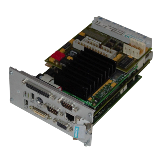
- Page 4 SMP16-CPU06x ©Siemens AG 2001, All Rights Reserved (4)J31069-D2085-U001-A2-7618...
- Page 5 Additional Interrupt Controller 4.7.3 Digital Inputs/Outputs Safety Functions 4.8.1 Voltage Monitoring 4.8.2 Battery Buffering 4.8.3 Watchdog 4.8.4 Temperature Monitoring 4.8.5 Password Protection 4.8.6 LEDs Operation without Fan 4.9.1 Setting via Setup 4.9.2 Regulated Operation ©Siemens AG 2001, All Rights Reserved (4)J31069-D2085-U001-A2-7618...
- Page 6 7.2.1 Input/Output for Internal Board Registers 7.2.2 Manual Throttling Register 7.2.3 General Purpose Ports (GPP) 7.2.4 SMB Register Set 7.2.5 Memory Input/Output on the SMP16 Bus 7.2.6 Direct Input/Output for SMP16 AT Boards ©Siemens AG 2001, All Rights Reserved (4)J31069-D2085-U001-A2-7618...
- Page 7 RMOS and Power Management/Fanless Operation 11.2 Installation Program 11.3 RMOS Configuration for the SMP16-CPU06x 11.3.1 Support of the Secondary EIDE Controller 11.3.2 TCP/IP Connection 11.3.3 Extra Interrupt Controller 11.3.4 SRAM Driver 11.3.5 System Generation ©Siemens AG 2001, All Rights Reserved (4)J31069-D2085-U001-A2-7618...
- Page 8 12.2 Layout of the CMOS RAM and the CDT 12.3 Use of the CDT during BIOS Startup 12.4 POST Codes 12.5 View of the Front Plate of the SMP16-CPU06x 12.6 Abbreviations and Terms ©Siemens AG 2001, All Rights Reserved (4)J31069-D2085-U001-A2-7618...
- Page 9 Use of the SMP16-CPU065 varies depending on the specific models of the individual boards, while such differentiation does not apply with the SMP16-CPU066! The SMP16-CPU066 does not have a PCI-PCI bridge which means that the CPCI backplane bus is PCI bus 0 of the SMP16-CPU066. ©Siemens AG 2001, All Rights Reserved (4)J31069-D2085-U001-A2-7618...
- Page 10 Introduction SMP16-CPU06x ©Siemens AG 2001, All Rights Reserved (4)J31069-D2085-U001-A2-7618...
- Page 11 Hard disk interfaces 40-pin pin strip (channel 0) and (EIDE, UDMA33) Expansion of the I/CPCI bus (channel 1) • Floppy disk interfaces 34-pin pin strip (drive A) and Expansion of the I/CPCI bus (drive B) ©Siemens AG 2001, All Rights Reserved (4)J31069-D2085-U001-A2-7618...
- Page 12 Analog monitor screen/ Socket, 15-pin, high density LVDS display Can be switched for display Resolution: 640x480 / 800x600 / 1024x768 • PanelLink display Socket, 26-pin HDP Resolution: 640x480 / 800x600 / 1024x768 • ©Siemens AG 2001, All Rights Reserved (4)J31069-D2085-U001-A2-7618...
- Page 13 Approx. 1.5 kg with AGP option Approx. 1.3 kg without AGP option Reliability (MTBF) With AGP, with SMP16 26.2 years With AGP, without SMP16 29.4 years Without AGP, with SMP16 30.3 years Without AGP, without SMP16 34.7 years ©Siemens AG 2001, All Rights Reserved (4)J31069-D2085-U001-A2-7618...
- Page 14 Technical Data SMP16-CPU06x ©Siemens AG 2001, All Rights Reserved (4)J31069-D2085-U001-A2-7618...
- Page 15 The flowcharts on the next few pages illustrate the procedure recommended for initial commissioning of the board. Initial commissioning Settings on the hardware Layout and special wiring of the bus backplane BIOS settings (see chapter 6.2) ©Siemens AG 2001, All Rights Reserved (4)J31069-D2085-U001-A2-7618...
- Page 16 CDT in flash and these are still valid, pin 2 and pin 12 must be connected on the LPT plug connector the next time the system is started (so that both the CMOS content and CDT are invalid). ©Siemens AG 2001, All Rights Reserved (4)J31069-D2085-U001-A2-7618...
- Page 17 IPCI system in the system storage insert for SMP16 system, and install rack. both together in the system rack. 1) PS 330 is required if PCI boards need 3.3 V. ©Siemens AG 2001, All Rights Reserved (4)J31069-D2085-U001-A2-7618...
- Page 18 (SMP16 or IPCI). Connect SMP16-CPU065 CPU board to mass storage insert for SMP16 system, and install both together in the system rack. 1) PS 330 is required if PCI boards need 3.3 V. ©Siemens AG 2001, All Rights Reserved (4)J31069-D2085-U001-A2-7618...
- Page 19 Clock pulses can be enabled separately. Bits 3, 4, 5 Gates can be addressed separately. R13C Bits 0,1,2 Clock pulses can be addressed with DI. Bits 4,5,6 Gates can be addressed with DI. ©Siemens AG 2001, All Rights Reserved (4)J31069-D2085-U001-A2-7618...
- Page 20 EIDE channel. SMP_INT can only be fed in with one of the SMP_IRQs. Starting with KS02: Depending on the EIDE channel SMP_INT is assigned to IRQ14 or IRQ15 (or neither of the two). ©Siemens AG 2001, All Rights Reserved (4)J31069-D2085-U001-A2-7618...
Need help?
Do you have a question about the SMP16-CPU06 Series and is the answer not in the manual?
Questions and answers