Advertisement
Advertisement
Table of Contents

Related Manuals for Davey Silensor


Summary of Contents for Davey Silensor
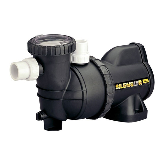
- Page 1 Silensor Pool Pump SERVICING INSTRUCTIONS...
- Page 2 Barrel unions need to be hand tightened. No sealant, glues, or • silicones are required. For all other trouble shooting and warnings please refer to the Silensor installation and operating instructions supplied with each pump or contact the Davey customer service centre on 1300 2 DAVEY (1300 232 839).
- Page 3 Tools Required Tools Required Ring spanner 13mm Davey Small Silensor spanner - Part number 13810-1SP Davey Large Silensor spanner - Part number 13810SP Davey bearing tools - Part number 48678 Davey Silensor bearing tool - Part number 48678-6 Bearing Press...
- Page 4 This makes it easier to unscrew the locking nut a flat blade screw driver break the plastic tab blocking the using the large Silensor spanner (part 13810SP). If the impeller nut. spanner is tight hit the spanner with a sharp tap of the...
- Page 5 With the small Silensor spanner (Part 13810-1SP) undo Remove the power lead from the non drive end shield, the locking nut at the rear of the motor and remove. You...
- Page 6 Sealing Ring O-ring Slinger Tap off the non drive end shield taking care not to damage To remove the rotor and perform a bearing change the wiring. Move the power cord out of its recess to a safe remove the slinger, O-ring and the front sealing ring in position before proceeding to the next step.
- Page 7 Remove the stator and shell and turn upside down on the Replace the front sealing ring, O-ring, and slinger. The small bearing tool then place back under the press. Insert motor is now ready for reassembly. the rotor being careful of the windings and then press it into the bearing with the press.
- Page 8 Replace the large case nut and bring the power lead push it into the cut out in the casing thread now you through it . can replace the casing nut and tighten it with the small Silensor spanner (part 13810-1SP).
-
Page 9: Mechanical Seal
Replace the rubber cover with the flanged end down Slide the outer cover down over the assembly so that the and lock it into the slot in the casing with the power lead slot lines up with the slot in the casing and the power lead running down the middle. - Page 10 With the pump facing you place the front casing against it Use the large spanner to tighten the nut. Be aware that and turn the casing nut anti clockwise to lock it in. There there is a lug on the nut that should not finish at the top are two slots in the motor casing that the front casing as it can interfere with the barrel union on the SLS model locks into.
- Page 11 The balance drum must be removed and the alternative arrangement utilising a Myler washer (p/n 13846*10) must be fitted during re-assembly. For further information please refer to service bulletin SP61/1550/1207. Silensor service tools 13810SP & 13810-1SP required to remove case nuts during servicing. DESCRIPTION PART NO.
- Page 12 Product specifications may change without notice. Drawings are indicative only, product appearance may change slightly. ® Davey is a registered trade mark of Davey Water Products Pty Ltd. © Davey Water Products Pty Ltd 2010. Davey Water Products Pty Ltd...
Need help?
Do you have a question about the Silensor and is the answer not in the manual?
Questions and answers