Interacoustics ad226 Instructions For Use Manual
Diagnostic audiometer
Hide thumbs
Also See for ad226:
- Instructions for use manual (575 pages) ,
- Instructions for use manual (195 pages)
Table of Contents
Advertisement
Advertisement
Table of Contents

Related Manuals for Interacoustics ad226


Summary of Contents for Interacoustics ad226
- Page 1 Instructions for Use - US AD226 Diagnostic Audiometer D-0103003-C - 2016/06...
-
Page 3: Table Of Contents
Save Session ......................14 3.9.2 View client ........................14 CARE AND MAINTENANCE ......................15 General Maintenance Procedures ..................15 How to clean Interacoustics Products ................16 Concerning Repair ......................17 Warranty ..........................17 GENERAL TECHNICAL SPECIFICATIONS ................19 Reference Equivalent Threshold Values for transducers ..........21 Pin Assignments ....................... 21... -
Page 5: Introduction
1.2 Intended Use The AD226 diagnostic audiometer is designed to be a device for diagnosing hearing loss. Output and specificity of this type of device are based on the test characteristics defined by the user, and may vary depending on environmental and operating conditions. The diagnosing of hearing loss using this kind of diagnostic audiometer depends on the interaction with the patient. -
Page 6: Warnings
AD226 Instruction for Use - US Page 2 1.4 Warnings Throughout this manual the following meaning of warnings, cautions and notices are used: WARNING indicates a hazardous situation which, if not avoided, could result in death or serious injury. CAUTION, used with the safety alert symbol, indicates a hazardous situation which, if not avoided, could result in minor or moderate injury. -
Page 7: Unpacking And Installation
Return Report will be of great help to us and is your best guarantee that the correction of the problem will be to your satisfaction. Storage If you need to store the AD226 for a period, please ensure it is stored uder the following conditions: Temperature: Transportation: -20° to 50°... -
Page 8: Marking
Failing to do so may endanger the environment. The CE-mark indicates that Interacoustics A/S meets the requirements of Annex II of the Medical Device Directive 93/42/EEC. TÜV Product Service, Identification No. 0123, 0123 has approved the quality system. - Page 9 No modification of this equipment is allowed without Interacoustics authorization. Interacoustics will make available on request circuit diagrams, component part lists, descriptions, calibration instructions, or other information that will assist service personnel to repair those parts of this audiometer that are designated by the Interacoustics as repairable by service personnel Never insert or in any way use the insert headset without a new clean non defect test tip.
- Page 10 AD226 Instruction for Use - US Page 6...
-
Page 11: Getting Started - Setup And Installation
AD226 Instruction for Use - US Page 7 3 Getting Started - Setup and Installation 3.1 Back Panel Connections – Standard Accessories When connecting to back panel connections tilt up/turn the instrument carefully for better overview. Patient Bone Left Phone... -
Page 12: Pc-Interface
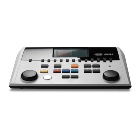
Please refer to the Diagnostic Suite operation manual regarding hybrid mode (on-line and PC-operated mode) as well as patient/session data transfer. 3.3 Operating instructions The figure below shows the outline of the front plate of the AD226 including buttons, dials and display: (13) (14) (15) - Page 13 AD226 Instruction for Use - US Page 9 7-12 Function Keys These keys are context sensitive and depend on the selected test screen. The fuctions of these keys will be explained further in later sections. Shift The shift function will enable the clinician to activate the sub functions written in italic underneath the buttons.
- Page 14 AD226 Instruction for Use - US Page 10 Mask on/off Masking channel on/off: First push: turns masking on Second push: turns masking off Sync This allows the masking attenuator to be locked to the tone attenuator. This option is used for e.g. synchronous masking.
-
Page 15: Tone Test
AD226 Instruction for Use - US Page 11 Battery operation Insert batteries correct according to marking. Use 4x1.5V/1.2V Alkaline/NiMH Type AA Note: When the instrument is battery powered or USB-only powered the maximum stimuli output level is reduced 20dB 3.4 Tone test... -
Page 16: Stenger Test
AD226 Instruction for Use - US Page 12 3.5 Stenger Test (12) (10) (11) Please refer to the Tone Test section above for key function descriptions for Function Keys (7), (8), (9), (10). 3.6 ABLB Test (10) (11) (12) Please refer to the Tone Test section above for key function descriptions for Function Keys (7), (8), (9),... -
Page 17: Hughson-Westlake Test
AD226 Instruction for Use - US Page 13 3.7 Hughson-Westlake Test (10) (11) (12) Text on screen Description Famili Select familarity Start HW test 3.8 Setup (10) (11) (12) Text on screen Description Tone Access the settings for the Tone Tests. -
Page 18: Sessions And Clients
AD226 Instruction for Use - US Page 14 3.9 Sessions and clients 3.9.1 Save Session (12) (10) (11) Text on screen Description Save Save session under the selected client. Delete Delete the selected client. Create new client. Edit Edit the selected client. -
Page 19: Care And Maintenance
Page 15 4 Care and Maintenance 4.1 General Maintenance Procedures The performance and reliability of the AD226 will be prolonged if the following recommendations for care and maintenance are adhered to: Great care when handling the headset: Great care should be considered when handling the headset as dropping it may alter the calibration. -
Page 20: How To Clean Interacoustics Products
Calibration procedure is available in service manual which is available on request. Do not modify this equipment without authorization. Interacoustics will make available on request relevant circuit diagrams, component part lists, descriptions, calibration instructions, or other information that will assist service personnel to repair those parts of this audiometer that are designated by the Interacoustics as repairable by service personnel 4.2 How to clean Interacoustics Products... -
Page 21: Concerning Repair
Page 17 4.3 Concerning Repair Interacoustics is only considered to be responsible for the validity of the CE marking, effects on safety, reliability and performance of the equipment if: 1. assembly operations, extensions, readjustments, modifications or repairs are carried out by authorised persons, 2. - Page 22 AD226 Instruction for Use - US Page 18...
-
Page 23: General Technical Specifications
EMC Standard IEC 60601-1-2:2007 Medical CE-mark Audiometer Standards Tone: IEC 60645-1:2012/ANSI S3.6:2010 Type 3 Calibration Calibration information and instructions is located in the AD226 Service manual TDH39: ISO 389-1 1998, ANSI S3.6-2010 Conduction DD45: PTB/DTU report 2009 E.A.R Tone 3A: ISO 389-2 1994, ANSI S3.6-2010... - Page 24 AD226 Instruction for Use - US Page 20 Intensity AC: -10 to 120 dB HL BC: -10 to 80 dB Available Intensity Steps is 1, 2 or 5dB Extended range function: If not activated, the Air Conduction output will be limited to 20 dB below maximum output.
-
Page 25: Reference Equivalent Threshold Values For Transducers
AD226 Instruction for Use - US Page 21 5.1 Reference Equivalent Threshold Values for transducers See Appendix in English in the back of the manual. 5.2 Pin Assignments See Appendix in English in the back of the manual. 5.3 Electromagnetic Compatibility (EMC) - Page 27 Survey of Reference and max Hearing Level Tone Audiometer ANSI TDH39 IEC TDH39 Coupler: ANSI S3.7-1995 (NBS-9A) / Coupler: IEC 60318-3 1998 (6ccm) IEC 60318-3 1998 (6ccm) Tone Audiometer Tone Audiometer Tone Narrow Band Noise Tone Narrow Band Noise ANSI S3.6-2010 ANSI S3.6-2010 ISO 389-1 1998 ISO 389-4 1994...
- Page 28 ANSI EAR 3A Coupler: ANSI S3.7-1995 (HA-2 with 5mm rigid Tube) Tone Audiometer Tone Narrow Band Noise ANSI S3.6-2010 ANSI S3.6-2010 IEC EAR 3A Frequency RETSPL MaxHL RETSPL MaxHL Coupler: IEC 60318-5 2006 26.0 30.0 Tone Audiometer 22.0 26.0 Tone Narrow Band Noise 18.0 22.0...
- Page 29 Coupler ANSI S3.7-1995 (HA-2) Tone Audiometer Tone Narrow Band Noise ANSI S3.6-2010 ANSI S3.6-2010 Frequency RETSPL MaxHL RETSPL MaxHL 26.0 30.0 22.0 26.0 18.0 22.0 14.0 18.0 12.0 16.0 13.0 1000 1250 1500 1600 2000 2500 11.0 3000 3150 10.0 4000 10.5 5000...
- Page 30 General properties for earphones Sound attenuation values for earphones Frequency Attenuation DD45 or TDH39 with MX41/ EAR-Tone 3A AR or PN 51 cushion [Hz] [dB] [dB] 33,5 34,5 34,5 1000 35,0 1250 1500 1600 2000 33,0 2500 3000 3150 4000 39,5 5000 6000...
- Page 31 AD226 Pin assignment Socket Connector Pin 1 Pin 2 Pin 3 Ground /1.6A DC Supply Left Right Ground Signal Bone Ins. Mask. 6.3mm Mono Pat. Resp. 6.3mm Stereo Ground Signal ch. 2 Signal ch. 1 3.5mm Stereo USB (host) USB (PC)
- Page 33 The use of accessories, transducers and cables other than those specified, with the exception of servicing parts sold by Interacoustics as replacement parts for internal components, may result in increased EMISSIONS or decreased IMMUNITY of the device. Anyone connecting additional equipment is responsible for making sure the system complies with the IEC 60601-1-2 standard.
- Page 34 Voltage dips, short < 5% UT (>95% dip in UT) < 5% UT (>95% dip in UT) (>95% dip in UT) interruptions and voltage for 0.5 cycle for 0.5 cycle for 5 sec Mains power quality variations on power supply should be that of a typical lines 40% UT (60% dip in UT)
- Page 35 Other : Date : Person : Please provide e-mail address or fax No. to whom Interacoustics may confirm reception of the returned goods: The above mentioned item is reported to be dangerous to patient or user In order to ensure instant and effective treatment of returned goods, it is important that this form is filled in and placed together with the item.
Need help?
Do you have a question about the ad226 and is the answer not in the manual?
Questions and answers