Sign In
Upload
Download
Table of Contents
Contents
Add to my manuals
Delete from my manuals
Share
URL of this page:
HTML Link:
Bookmark this page
Add
Manual will be automatically added to "My Manuals"
Print this page
×
Bookmark added
×
Added to my manuals
Manuals
Brands
Asko Manuals
Ventilation Hood
CC4727S / 4000
Instructions for use manual
Asko CC4727S / 4000 Instructions For Use Manual
Hide thumbs
1
2
Table Of Contents
3
4
5
6
7
8
9
10
11
12
13
14
15
16
page
of
16
Go
/
16
Contents
Table of Contents
Bookmarks
Advertisement
Table of Contents
1
Instructions for Use
2
Table of Contents
3
Description
4
Controls
5
Cleaning
6
Removing the Grease Filters
7
General
8
Electrical Connection
8.1
Technical Specifications
8.2
Appendix
9
Disposal of Appliance and Packaging
Download this manual
Instructions for use
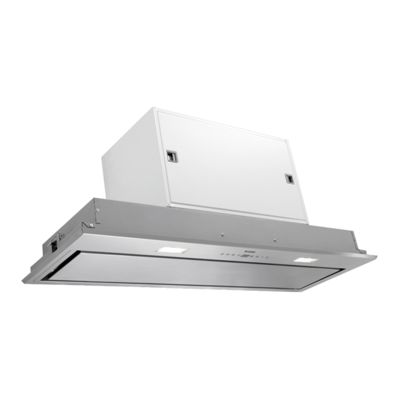
Built-in unit
CC4727S / 4000
CC4927S / 4000
CC41227S / 4000
Table of
Contents
Previous
Page
Next
Page
1
2
3
4
5
Advertisement
Table of Contents
Need help?
Do you have a question about the CC4727S / 4000 and is the answer not in the manual?
Ask a question
Questions and answers
Related Manuals for Asko CC4727S / 4000
Ventilation Hood Asko CC4840S Operating Instructions Manual
Cooker hood (17 pages)
Ventilation Hood Asko CC4520 Operating Instructions Manual
(14 pages)
Ventilation Hood Asko CC4927S / 4000 Instructions For Use Manual
(16 pages)
Ventilation Hood Asko CCT1252W Instructions For Use Manual
(16 pages)
Ventilation Hood Asko CC4527S Instructions For Use Manual
Built-in unit (28 pages)
Ventilation Hood Asko CC4525S Instructions For Use Manual
(19 pages)
Ventilation Hood Asko CCT9051S Instructions For Use Manual
(16 pages)
Ventilation Hood Asko CCT1252WC Instructions For Use Manual
(36 pages)
Ventilation Hood Asko CCT9051SC Instructions For Use Manual
(38 pages)
Ventilation Hood Asko CG1 User Instructions
Asko cg1 range hood: user guide (25 pages)
Ventilation Hood Asko CH060-60 Use And Care Manual
Asko ch060-60 ventilator: user guide (20 pages)
Ventilation Hood Asko CW 4985 Instructions For Use Manual
(22 pages)
Ventilation Hood Asko CO4927S Instructions For Use Manual
Telescopic cooker hood (20 pages)
Ventilation Hood Asko CBB901SB Instructions For Use Manual
(12 pages)
Ventilation Hood Asko CBB761S Instructions For Use Manual
(20 pages)
Ventilation Hood Asko CBB861S Instructions For Use Manual
(19 pages)
This manual is also suitable for:
Cc41227s / 4000
Cc4927s / 4000
Table of Contents
Print
Rename the bookmark
Delete bookmark?
Delete from my manuals?
Login
Sign In
OR
Sign in with Facebook
Sign in with Google
Upload manual
Upload from disk
Upload from URL


Need help?
Do you have a question about the CC4727S / 4000 and is the answer not in the manual?
Questions and answers