Table of Contents
Advertisement
Quick Links
Advertisement
Table of Contents

Related Manuals for DSC PC560


Summary of Contents for DSC PC560
- Page 1 INSTALLATION MANUAL PC56O Version 1.OA...
-
Page 2: Table Of Contents
TABLE OF CONTENTS INTRODUCTION Features ..............................3 Specifications ............................3 INSTALLATION Mounting the Control Panel ........................4 Mounting the Keypad ..........................4 Wiring ..............................5 Burglary Zone Wiring ..........................5 Auxiliary Power Connection ........................5 PGM OUT Terminal Connection ......................5 STR Terminal Connection ........................ - Page 3 PROGRAMMING GUIDE Sections [05] through [07]: Selecting System Functions ..............11 HEX Data Programming ........................11 Resetting Programming to the Factory Default Settings ............... 11 PROGRAMMING SECTIONS [01] Zone Definitions ..........................12 [02] System Times ..........................13 [03] Installer’s Code ..........................13 [04] Programmable Output Options (PGM OUT Terminal) ..............
-
Page 4: Introduction
INTRODUCTION FEATURES SPECIFICATIONS • Fully featured security system with Trouble PC560 Control Panel Supervision, Alarm Memory, Master Code and 3 • Four fully programmable zones programmable Access Codes, Quick-Arming and • Zones are End-of-Line Resistor supervised At-Home Arming, Door Chime, 3 one-touch Keypad •... -
Page 5: Installation
It is recommended that appropriate wall anchors be used when securing the cabinet to drywall, plaster, concrete, brick or other similar surfaces. Press the PC560 Control Panel onto the nylon mounting studs. Pull all cables into the cabinet and prepare them for connection. -
Page 6: Wiring
Wiring NOTE: Complete all wiring to the control panel before applying battery or AC power. Burglary Zone Wiring Burglary zone definition, (for example, Delay, Instant, 24-Hour, and so on) is programmed using the keypad. Refer to Programming Guide Section [01]. NOTE: To help prevent false alarms, all zones are automatically bypassed for 120 seconds on power-up to allow detectors to settle. -
Page 7: Str Terminal Connection
STR Terminal Connection The STR (strobe output) terminal is a normally open output that will switch to ground when activated. This output will be activated when a zone alarm or tamper alarm is generated while the system is armed. The output will remain activated until the system is disarmed. -
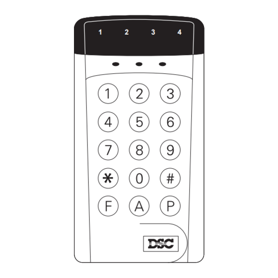
Page 8: Keypad Functions
Master Code A default Master Code “1234” is factory programmed into the PC560. The Master Code is used to arm and disarm the system, to silence the bell or siren after an alarm, and to program additional Access Codes. The ∗... -
Page 9: Disarming
]+[2]: Display Trouble Conditions The PC560 continuously monitors a number of trouble conditions. If one of these conditions occurs, the keypad “System” light will come ON and the sounder will sound two short beeps every 10 seconds. To silence the sounder, press the [#] Key;... -
Page 10: Display Alarm Memory
∗ ]+[8]+[Installer’s Code]: Installer’s Programming Command ∗ The PC560 is programmed from the keypad by using commands in the [ ][8][Installer’s Code] section. These commands are described in detail in the Programming Section of this manual. The default Installer’s Code... -
Page 11: At-Home Arming
If all power to the system is shut off, each Keypad’s tone and backlighting will be restored to the factory settings. NOTE: WARNING Some models of the PC560 have a special lockout feature that prevents the control panel from being reset to the factory default programming. Call DSC Australia if you are attempting to take over a system installed by another security company. -
Page 12: Programming Guide
7 Remove the short between the PGM OUT and Zone 1 terminals 8 Re-connect original wiring to the PGM OUT and Zone 1 terminals 9 Restore power to the PC560; the Programming Sections have now been restored to the factory default settings... -
Page 13: Programming Sections
PROGRAMMING SECTIONS [01] Zone Definitions Enter four 2-digit numbers in this section to determine the operating characteristics of each zone. Zone Definitions: Digit 1 The first digit of each Zone Definition determines each zone’s audible alarm characteristics. When programmed as audible, the siren will sound on alarm; when programmed as silent, the siren will not sound on alarm. Note that zone response times are factory set at 500 ms. -
Page 14: System Times
[02] System Times Three system times are programmed in Section [02]; each time requires a 3-digit number. Do not press the [#] Key during data entry. Entry Delay (001 to 255 seconds) The Entry Delay determines the amount of time permitted between the activation of a Delay Zone and the disarming of the system. -
Page 15: 1St System Option Code
Ringback disabled • Factory default settings If DLS Answer is disabled, the PC560 will not answer calls from a downloading computer. If DLS Answer is enabled, the system will only connect to the downloading computer using the “double call” technique. The system must be called by the downloading computer, and the computer must allow the telephone line to ring only once or twice. -
Page 16: 3Rd System Option Code
Private Line Format The Private Line format will only transmit zone alarms for which reporting codes are programmed in Section [11]; [F], [A] and [P] Key alarms will not be reported by this format. Do not program any reporting codes other than the Alarm Reporting Codes for Zones 1 through 4 and the Tamper Zone. -
Page 17: First Phone Number
[08] First Phone Number This is the first telephone number the Communicator will dial when an alarm is generated. Enter the telephone number the same way it would be dialled on a touch-tone phone. Press [#] after the last digit to complete the telephone number programming. -
Page 18: Maintenance And Priority Codes
[13] Maintenance and Priority Codes Maintenance Codes are transmitted to indicate various trouble conditions and their restorals; Priority Codes are used to indicate the activation of the [F], [A] and [P] keys. Program a 2-digit code for each of the following conditions: •... -
Page 19: For The Record
PC560 v1.0A FOR THE RECORD Customer ___________________________________________________________________________________ Address ___________________________________________________________________________________ ___________________________________________________________________________________ Phone ________________________________ Installation Date ____________________________ CONTACTS Name ________________________________ Phone ________________________ Name ________________________________ Phone ________________________ Name ________________________________ Phone ________________________ ZONE INFORMATION Zone Type Protected Area ____________________ _______________________________________________________ ____________________ _______________________________________________________ ____________________ _______________________________________________________... -
Page 20: Programming Worksheets
PC560 v1.0A PROGRAMMING WORKSHEETS [01] Zone Definitions Page 12 NOTE: When defining zones, assign delay zones first, then assign the other types. Default Digit 1 Digit 2 [0] Audible [0] Standard Delay Zone 1 [1] Silent [1] Instant Zone 2... - Page 21 PC560 v1.0A [06] 2nd System Option Code Page 14 Default Zone Light ON Zone Light OFF Zone Light 1 Private Line 40 BPS 4/2 with parity Zone Light 2 1400Hz Handshake 2300Hz Handshake Zone Light 3 DLS Answer enabled DLS Answer disabled...
- Page 22 PC560 v1.0A [11] Zone Alarm and Restoral Reporting Codes Page 16 For single digit reporting codes, enter [0] as the second digit. ∗ ∗ Zone 1 Alarm Enter [ ] (HEX A) to transmit a “0” (zero = 10 pulses)
- Page 23 PC560 v1.0A [13] Maintenance and Priority Codes Page 17 For single digit reporting codes, enter [0] as the second digit. ∗ ∗ Battery Trouble Enter [ ] (HEX A) to transmit a “0” (zero = 10 pulses) Battery Restore Periodic Test Code...
-
Page 24: Hook-Up Diagram
Detection devices that require power from the Control Panel should operate over the range of 10.0 to 14.0 VDC. The DSC BRAVO models are recommended motion detectors. The DSC DG-50 is a recommended glassbreak detector. Temperature Range: 0˚C to 49˚C (32˚F to 120˚F). Maximum Humidity: 85% relative humidity... -
Page 25: Limited Warranty
LIMITED WARRANTY Digital Security Controls Ltd. warrants that for a period of twelve months from the date of purchase, the product shall be free of defects in materials and workmanship under normal use and that in fulfilment of any breach of such warranty, Digital Security Controls Ltd. - Page 26 © 1995 Digital Security Controls Ltd. 29001315 R0 1645 Flint Road, Downsview, Ontario Canada M3J 2J6 April 25 1995 Telephone: (416) 665 8460 Fax: (416) 665 7498...
Need help?
Do you have a question about the PC560 and is the answer not in the manual?
Questions and answers