Table of Contents
Advertisement
Rev-5
PIN NUMBER: 0558bl5590
INSTALLATION MANUAL & USER HANDBOOK
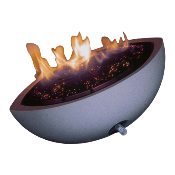
Small Oval Gas Fire Bowl
[with Remote Control Ignition System]
For use with Natural Gas or LPG/Propane (See Data Plate)
Important
It is recommended, even if you have fitted these appliances
before, that you take the time to read through these
instructions and ensure that you follow them step by step.
Serial Number ....................................
Please quote this serial number when calling our Customer Service team
regarding Warranty issues or to order spare parts. The warranty is valid
for 1 Year from the date of delivery. The Warranty card supplied is to be
completed by the Installer and returned to the address below.
This manual must be handed to the owner of the property once the
fire is commissioned and retained for future reference.
Spirit Fires Ltd. Unit 4 Beaumont Square, Aycliffe Industrial Park, Newton Aycliffe, County Durham, DL5
6XN. Tel: 01325 327221, Fax: 01325 327292, Email: info@cvo.co.uk, Web: www.cvo.co.uk
Advertisement
Table of Contents

Related Manuals for CVO Fire 0558bl5590


Summary of Contents for CVO Fire 0558bl5590
- Page 1 Rev-5 PIN NUMBER: 0558bl5590 INSTALLATION MANUAL & USER HANDBOOK Small Oval Gas Fire Bowl [with Remote Control Ignition System] For use with Natural Gas or LPG/Propane (See Data Plate) Important It is recommended, even if you have fitted these appliances before, that you take the time to read through these instructions and ensure that you follow them step by step.
-
Page 2: Table Of Contents
Contents Page 3 Technical Data Page 4 Unpacking the Appliance Page 5 Remote Control Information Page 6 General Requirements Page 7 Installation Instructions Page 10 Commissioning the Fire Page 11 Re-setting the Appliance Page 13 Remote Control Options Page 14 Lighting the Fire Page 20 Fault Diagnosis &... -
Page 3: Technical Data
Technical Data Specifications Pilot Burner Assembly NG: P4/10 (or P4/10D, Holland Only), LPG: P4/16 Gas Inlet Connection 8mm O.D. Tube Minimum Flue Diameter 178mm Minimum Flue Height Approximate Weight 22kg Small Oval Gas Fire Unit Main Burner Heat Setting Inlet Injector Input Pressure... -
Page 4: Unpacking The Appliance
IS 813 and ICP3 and any guidance notes from Bord Gais. Failure to have the fire fitted by a qualified person will invalidate the Warranty, and CVO Fire will not accept any claims for incorrect installation. -
Page 5: Remote Control Information
IS 813 and ICP3 and any guidance notes from Bord Gais. Failure to have the fire fitted by a qualified person will invalidate the Warranty, and CVO Fire will not accept any claims for incorrect installation. Power Supply... -
Page 6: General Installation Requirements
General Installation Requirements This fire is intended for decorative purposes. The installation must be in accordance with National Regulations and must be carried out by a qualified installer. Clearances between the fire and all combustible materials must conform to National Regulations. This fire must be installed and used in accordance with these instructions. - Page 7 Installing the Fire Bowl. The installation should only be carried out by a qualified Gas Safe Registered fitter and in accordance with National and local Regulations for both gas and electricity otherwise this will invalidate your guarantee. Step-1 Check the packing label on the box to confirm gas type and gas pressure required for the bowl to be fitted and ensure this complies with the property supply.
- Page 8 Diagram of Burner Removal Step-4 • Once removed place he burner unit in a safe location. • The base of the bowl has holes which can be used to secure the fire bowl into the enclosure by the use of screws and rawl plugs. See Diagram below.
- Page 9 Step-5 • Decide the location of the “Hard Wire” Remote switch. • Remove the switch from the “GREY” hard wire cable and store in a safe place. • Route the grey cable to the desired location and refit the wall switch ensuring the wiring is in the correct order [see wiring diagram] –...
-
Page 10: Commissioning The Fire
Small Oval Remote Burner – Perspective View of Back: NOTE: Gas inlet runs through the back hole of the bowl Commissioning the Fire TEST THE GAS PRESSURE. Turn the fire on full; attach a manometer to the inlet test point and ensure there is a pressure of 20mbar (+/- 1mbar) for natural gas appliances or 37mb for propane appliances. -
Page 11: Re-Setting The Appliance
Registration. If the appliance is not fitted in strict accordance with these instructions this will invalidate the Warranty, and CVO Fire will not accept any claims for incorrect installation. CVO Fire cannot be held responsible for any damage caused due to incorrect installation and reserve the right to charge for any corrective work. - Page 12 The wall mounted switch and cable carries low voltage, (20v). The colour code used in the switch wiring diagrams must not be confused with normal mains colour coding. Option 1 – Choosing the Infra-Red System The following procedure should be carried out: Trace the cable on the wall-mounted switch back to the main body of the fire.
-
Page 13: Remote Control Options
Remote Control Options The remote system is supplied with both the hardwired wall switch and infrared system as standard. Both options can be used as tandem; alternatively the remote control can be used without the wall-mounted switch and vice versa. It is very important when removing an option it is done correctly in order for the option left to function correctly on its own. -
Page 14: Lighting The Fire
Lighting the Fire Infra-Red Remote Operation Infrared systems require “Line of sight” between the handset and the sensor at the appliance, it is a standard safety feature to ensure that the appliance cannot be remotely lit from another room. Hardwired Wall Mounted Switch Press the ON/OFF bottom (left side) for 2-3 seconds (until the spark ignition sequence begins) and release. - Page 15 Press the HIGH/LOW button (right side) for 2-3 seconds the appliance will change to low rate. This operation is repeated to switch between high and low. Page 15 of 31...
- Page 16 Infra-Red Remote Operation Infrared (IR) systems require “Line of sight” between the handset and the appliance. This is a standard feature to ensure the appliance cannot be lit from another room. Page 16 of 31...
- Page 17 Infra-Red Remote - Replacing the Battery The Remote Controls - Black Box Page 17 of 31...
-
Page 18: Spark Failure
Remote Valve Spark Failure The gap between the pilot electrode and the pilot should be 3.5 – 4.5mm and normally adjustment is not necessary (the electrode is very brittle). The spark should jump across the gap between the electrode and the gas outlet on the pilot head. If the ignitor fails, a lighted taper can be inserted into the pilot area to check that gas is reaching the pilot. - Page 19 Remote Wiring Diagram 8.11 Troubleshooting for Remote version All CVO Fires are given a full function test at the factory including being run for a number of minutes on full gas supply to ensure that the unit functions correctly. It is highly unlikely, that if the unit has been installed correctly as set out in this manual that the fire will not function.
-
Page 20: Fault Diagnosis & Troubleshooting
Fault Diagnosis Symptom Check List Tick Check remote handset is working properly and battery is charged Unit does Check power supply has not been switched off not respond Check fuses in spur Check wiring is correct on fire and hardwire switch Remote Check battery power handset... - Page 21 INSTALLATION MANUAL & USER HANDBOOK Small Oval Gas Fire Bowl [with Remote Control Ignition System] For use with Natural Gas or LPG/Propane (See Data Plate) Important It is recommended, even if you have fitted these appliances before, that you take the time to read through these instructions and ensure that you follow them step by step.
- Page 22 Contents Page 23 General Instructions Page 24 Exchangeable Components List Page 25 Servicing Instructions Page 26 Cleaning Instructions Page 29 Fire Guards & Other Information Page 30 Warranty Information Page 22 of 31...
- Page 23 GENERAL INSRUCTIONS This fire is intended for decorative purposes. Any purpose-provided ventilation should be checked regularly to ensure that it is free from obstruction. The fire should be serviced regularly by a qualified person. The chimney should be swept before the appliance is installed, and should be swept and inspected regularly to ensure that all of the products of combustion are entering the flue and there is no excessive build up of soot.
- Page 24 Exchangeable Components List Engineer User Part Code Item Description Exchange Exchange Code Number Parts? Parts? GC002 Gas Valve (Remote) GC002 AC009 Pilot Unit (NG Remote) P4-05 Pilot Unit (LPG Remote AC007 P4-16 with M9 Nut) Small Flame Picture Injector AC021 (NG/Remote) CVO/460 Small Flame Picture...
-
Page 25: Servicing Instructions
Servicing Instructions General The following servicing procedure should be carried out regularly and only by a qualified person. Note: foreign bodies which can gather on the surface of the burner unit it is inevitable that servicing can be a dusty operation. Suitable precautions should be taken. -
Page 26: Cleaning Instructions
If the scuff mark persists it may be necessary to use a stronger cleaner. Please contact CVO Fire for details. Page 26 of 31... - Page 27 Removing Powders, Soot, Ash or Grit These should be removed without the use of liquids of any kind. Best results are achieved by using a vacuum cleaner; to lift the particles from the surface of the surround, or by blowing or fanning the particles away with a piece of card.
- Page 28 When completing the annual service of the Bronze Cube Unit, refer to the enclosed technical installation and operational manual & the optional remote control instruction document. The gas unit should be installed to the manufacturer’s instructions by a Gas Safe registered gas installer, every 12 months the gas fire unit should undergo a regular service, this work should be carried out by a competent person who is Gas Safe registered and familiar with the CVO Fire range of goods.
- Page 29 Bowls which are manufactured from Cast Metal are sand cast at a UK Foundry and then Hand Polished for over 15 Hours at the CVO Fire Factory. Pitting and Air Holes are a normal occurrence and are a part of the unique quality of such a hand made piece.
- Page 30 WARRANTY This appliance is supplied with a manufacturer’s warranty which is valid from 12 months from date of delivery. The Warranty covers defective components only and does not cover damage caused by incorrect installation or normal wear and tear caused by usage. When making a Warranty claim you will be required to supply the serial number of the appliance [as shown on the front of this booklet] and full details of the GAS SAFE registered...
- Page 31 ONLY USE GENUINE REPLACEMENT PARTS To order Spare Parts please contact Customer Services on 01325 327221. Opening hours are 9.15am to 3.15pm Monday to Friday. For further Technical information please call our CVO Technical Department on 01325 327221. Spirit Fires Ltd. Unit 4 Beaumont Square, Aycliffe Industrial Park, Newton Aycliffe,...
Need help?
Do you have a question about the 0558bl5590 and is the answer not in the manual?
Questions and answers