Table of Contents
Advertisement
Quick Links
Advertisement
Chapters
Table of Contents

Related Manuals for Nera Inmarsat-c

Summary of Contents for Nera Inmarsat-c
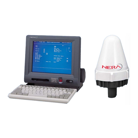
- Page 1 Nera C Service Manual INMARSAT-C MOBILE EARTH STATION...
-
Page 3: Table Of Contents
1.3.3 [LAN] port......................1-5 1.3.4 [DTE] port ......................1-5 1.3.5 [D-GPS] port ....................1-5 Chapter 2. Block Description 2.1 Configuration.........................2-1 2.1.1 Nera C......................2-1 2.1.2 Boards in each unit ..................2-2 2.2 Antenna unit, IC-115 .....................2-4 2.2.1 ANT RF board (16P0207) ................2-4 2.2.2 Antenna element .....................2-5 2.3 Terminal unit, IC-215 ....................2-6... - Page 4 Contents Chapter 4. Set up 4.1 System menu (F8)......................4-1 4.1.1 Setting by DTE port..................4-1 4.1.2 System menu (F8)...................4-2 1. Distress Alert Setup: [F8]-1.................4-2 2. System Setup: [F8]-2 ...................4-2 3. Editor Setup (Close the TEXT editor display.) : [F8]-3 ......4-4 4. Terminal Setup: [F8]-4 ................4-5 5.
- Page 5 Contents 5.7 Checking LES Information....................5-18 5.8 Changing Back-up battery on TERM CPU board ............5-20 5.9 Clearing Memory......................5-21 5.10 Distress alert test......................5-22 5.11 Saving and loading of system setting................5-24 Chapter 6. Updating program 6.1 Updating program......................6-1 6.1.1 Checking program version ................6-1 6.1.2 Procedure ......................6-2 6.2 Program files........................6-3 6.3 Installing Terminal software to PC ................6-3...
- Page 6 Contents Appendix 1) Inmarsat system ..............AP1-1 AP1.1 System Overview ..................AP1-1 AP1.1.1 System Configuration ................AP1-1 AP1.1.2 Inmarsat C Services ................AP1-3 AP1.1.3 Destination Type ................AP1-4 AP1.1.4 Charging.....................AP1-6 AP1.1.5 Network .....................AP1-7 AP1.1.6 Frequency assignment................AP1-9 AP1.2 Message & Signal Transfer................AP1-10 AP1.2.1 Ship- originated Call ................AP1-10 AP1.2.2 Shore- originated Call ................AP1-12 AP1.2.3 Log in/Log out ...................AP1-15 AP1.2.4 Distress Alert ..................AP1-16...
- Page 7 Contents AP4.8 Connection and setting..................AP4-9 AP4.8.1 Connection to single PC ..............AP4-9 AP4.8.2 Connection of multiple PCs...............AP4-11 AP4.8.3 Connection to multiple networks............AP4-12 AP4.9 Function settings ...................AP4-14 AP4.9.1 DHCP....................AP4-14 AP4.9.2 SMTP Enable IP Address ..............AP4-15 AP4.9.3 Mail Gateway..................AP4-16 AP4.9.4 Selective forwarding ................AP4-18 AP4.9.5 Message size ..................AP4-20 AP4.9.6 Attachment conversion ..............AP4-21 AP4.10 E-mail Client Setup (Outlook Express Ver.6)..........AP4-22...
-
Page 8: Check List
: IMN, AAB, CS, etc unit. 2. Program version See chapter 6. The program version is checked by “Diagnostic Test” (keystroke: [F7]-7-3). For the detail version, type “Nera” while pressing [Ctrl]. Table2. Program version Program Detail version TERM CPU 1650162-01.xx RF CON/CPU 1650159-01.xx... - Page 9 Check List 3. Settings Table 3 lists check items for the setting. Table 3. Items to be set Items to be set Result Reference to [F8]-2: Command Window DMC-5 “Remote Box Setup” [F8]-2: Command Window IC-305 “Remote Box Setup” [F8]-2: Command Window IC-306 “Remote Box Setup”...
- Page 10 Check List 4. Checking Table 4 is the check list for items to be set. Table 4. Check list for items to be set Refere Items to be checked Result nce to When [ALARM RESET] is pressed, the IC-306 buzzer and LED is an active. IC-305 [F7]-7-4: Distress Alert Button Test 5-22...
- Page 11 Check List 5. Communication test Before the test, check followings. 1) C/N of the status display is OK. 2) Its value is stable. 3) “Current Status” is “Idle”. 5.1 Log in When Log in ([F7]-1) is succeeded, “Successful Login” appears. If the trouble message appears, see the list below.
- Page 12 Check List 5.3 Loop back test Start Loop back test which the message is send back to the own ship. The transmitting and receiving message should be printed out. 1) Make a test message by “New” ([F1]-1). 2) Set following items by “Transmit Message” ([F3]-1). - Priority : Normal - Destination Type...
- Page 13 To cancel the distress alert, report by the priority message (Priority: Distress ) to proper RCC via LES which is used to transmit the distress alert. Example; NAME, CALLSIGN, ID NUMBER, POSITION Cancel my INMARSAT-C distress Alert of DATE, TIME UTC. =Master+ 7. Clearing memory When the trouble occurs, clear the memory before changing the board or the units.
- Page 14 Check List Non-delivery Notification Failure Codes Absent subscriber. The mobile terminal is not logged-in to the ocean region. Access barred. Addressee refuses to accept message. Deleted. The message has not been delivered within an hour and is therefore deleted. Attempting to deliver the message. Message aborted.
- Page 15 Check List Network congestion. Operator aborted. Subscriber is occupied. Out of order. Packet assembler/disassembler. Premature clearing. Protocol failure. Reverse changing acceptance not subscribed. There was a failure in the remote equipment. Resource limit exceeded. Remote procedure error. RPOA out of order. Call completed successfully.
-
Page 16: Chapter 1. General
1.1 General Nera C is a successor of "Nera C12". Nera C is a communication system of Class 2 Inmarsat C which is smaller and lighter than "Nera C12". The operation is the same as "Nera C12". Nera C has 10BASE-T port to communicate by E-mail from PC connected to LAN. -
Page 17: Configuration
1.2 Configuration 1.2 Configuration To use the cable other than TP5FBAW-5DFBB, optional N-TNC converting cable is needed to both the antenna unit and the terminal unit. Fig.1.2.1 Nera C system configuration... -
Page 18: Connection
1.3 Connection 1.3 Connection 1.3.1 Antenna and terminal unit The antenna unit, IC-115 and terminal unit, IC-215 are connected by the coaxial cable. This coaxial cable includes 1530.0 MHz to 1545.0 MHz receiving RF signal, 1626.5 MHz to 1646.5 MHz transmitting RF signal, 1575.42 MHz receiving GPS RF signal and the power supplied to the antenna unit. - Page 19 1.3 Connection 1) Connecting the distress alert received unit and ALAM unit The distress alert received unit: IC-305 and up to 3 ALARM units: IC-306 are connected to port #1 to #4 in parallel. The electrical rating of port #3 and #4 (TD/RD-A/B) connecting line is RS-485.
-
Page 20: Lan] Port
1.3 Connection 1.3.3 [LAN] port 10Base-T, RJ-45 connector is used for Ethernet LAN. Terminal unit includes the mail gateway function such as SMTP and POP3 so that the E-mail communication is available from the PC connected to LAN by using Inmarsat C. Up to 32 k bite data is sent from the Inmarsat C. -
Page 21: Chapter 2. Block Description
Chapter 2. Block Description 2.1 Configuration 2.1 Configuration 2.1.1 Nera C Fig.2.1.1 shows the block diagram of the terminal unit, Nera C. Fig.2.1.1 Block diagram of terminal unit, Nera C... -
Page 22: Boards In Each Unit
1) Consisting of RF amplifier circuit and the dielectric filter which dividing TX/RX signal. The difference from 2) Changing TX and RX circuit by Nera C12. antenna supplied voltage, TX 29 V/RX 1) The diplexer is changed 7 V. to the dielectric filter. - Page 23 2.1 Configuration I/F rating - Printer: Centronics - PC: RS-232C Communicating with followings; - Distress Alert Received/ TERM/CPU LCD, Printer, PC, Distress Alert Received ALERT unit : RS-485 (16P0209) unit, ALERT unit, NAV data, Ethernet, - NAV data inputting: FDD, keyboard and RF-CON/CPU board. GGA, GLL, WPL, VTG, RMA, RMB, RMC, MTW, DBT, VDR, BWC, BWR...
-
Page 24: Antenna Unit, Ic-115
2.2 Antenna unit, IC-115 2.2 Antenna unit, IC-115 The antenna unit consists of ANT RF board (16P0207), ANT B(16P0206) and the daisy loop type antenna element. 2.2.1 ANT RF board (16P0207) ANT RF board consists of the transmitting RF amplifier circuit, the receiving RF amplifier circuit, the voltage changing circuit of TX/RX circuit and the heat protecting circuit. -
Page 25: Antenna Element
2.2 Antenna unit, IC-115 2.2.2 Antenna element Antenna unit consists of the element, the 3 dB hybrid and the reflector. The antenna unit is called “DAISY LOOP ANT antenna”. ANT RF output, 42 dBm of 1.6 GHz is radiated from the antenna by 14 dBW of EIRP. The receiving signal of the power flux density, -148 dBW/m to –136 dBW/m of 1.5 GHz is input to... -
Page 26: Terminal Unit, Ic-215
RF CON/CPU board and TERM CPU board are communicated by RS-232C. The transmitting control unit such as Nera C 10/11/12 has the function of RF CON/CPU board, and the terminal unit such as IC-511/IB-581 has the function of TERM CPU board. -
Page 27: Rf Con/Cpu Board (16P0208A)
2.3 Terminal unit, IC-215 2.3.1 RF CON/CPU board (16P0208A) The following describes the function of RF CON/CPU board. Analog part - Dividing the received RF signal to [D-GPS] terminal for D-GPS decoder. - Dividing the received RF signal to GPS receiving board (GN-79, option). - Changing the received RF signal to the IF signal: 1.2 kHz. - Page 28 2.3 Terminal unit, IC-215...
- Page 29 2.3 Terminal unit, IC-215 1) Receiving part Receiving circuit The RF signal from the antenna unit is input to the receiving circuit by the diode switch, CR20. FL13 of the receiving circuit is B.P.F of 1.5 GHz. The BPSK modulating RF signal is changed to 1.2 kHz intermediate frequency at Hybrid (U21) and DBM (U12 and U9) and then input to CPU (U14) as I and Q signals.
- Page 30 2.3 Terminal unit, IC-215 Frequency control For example, when the receiving frequency from the satellite differs from the carrier frequency input to the de-modulating circuit, the error rate is increased. CPU detects the frequency difference and the phase difference of I signal and Q signal. The detection data controls the frequency of the TX/RX PLL synthesizer oscillator (TCXO: 16.8 MHz) so that the output frequency is equal to the receiving frequency by controlling the PLL synthesizer output frequency.
- Page 31 2.3 Terminal unit, IC-215 2) Transmission part BPSK modulation The transmission frequency is set at CPU. The data is processed by the data to be transmitted according to the channel below. - Transmitting MES signaling channel Message – Scrambling -- Convolutional encoding -- Adding unique word -- BPSK modulating - Transmitting MES message channel Message -- Scrambling -- Convolutional encoding -- Adding unique word --...
- Page 32 2.3 Terminal unit, IC-215 PLL and DDS circuit DDS output is about 1.6 MHz. When transmitting, it is BPSK modulated. Fig.2.3.7 shows the block diagram of DDS. Fig.2.3.7 Block diagram of DDS U4 divides it into 16 frequencies to change to about 100 kHz. About 100 kHz is mixed to the reference oscillation frequency, 16.8 MHz to generate about 16.9 MHz.
- Page 33 2.3 Terminal unit, IC-215 3) CPU CPU, HD64F7065 is 32 bit single tip microcomputer with DSP function. It consists of ROM (256 kbyte), RAM (8 kbyte), A/D (8 channels), D/A (2 channels), Timer (8 channels), watch-dog timer (1 channel) and Serial communication I/F (3 channels). RF CON/CPU board communicates with TERM CPU board by TD and RD signals which are I/F of RS-232C.
- Page 34 2.3 Terminal unit, IC-215 4) Memory EEPROM (8 kbyte) and SRAM (256 kbyte) are connected to CPU. SRAM is backed up by C90 (2.2 F) super capacitance for 72 hours. Table 2.3.1 lists the memory contents of RF CON/PU board. Table 2.3.1 Memory contents of RF CON/CPU board Memory Volume...
- Page 35 The priority sequence of the talker is GP>TR>LC>LA>DE>OM>II>IN. The priority sequence of the position data is GGA>RMC>GLL>RMA. Fig.2.3.12 shows the NMEA data connection. Fig.2.3.12 NMEA data connection Table 2.3.2 Receivable NMEA data Nera C GPS (GN-79) Formatter Description receiving formatter...
- Page 36 2.3 Terminal unit, IC-215 6) Connecting IC-305 and IC-306 The Distress Alert Received unit, IC-305 and Alarm unit, IC-306 (a maximum of 3) are connected to RF CON/CPU board via RS-485 rating interface. The function of the distress alert and the incoming indicator of the distress message and the emergency messages are provided to IC-305.
- Page 37 2.3 Terminal unit, IC-215 7) Handling of Alarm Table 2.3.4 lists the alarm output. Table 2.3.4 Alarm output EGC message reception Alarm when TLX/E-mail DIS ACK Category Unit detecting reception reception following to “TROUBLE” IC-215 Output Output Output Output Not output Output IC-305 Not output...
- Page 38 2.3 Terminal unit, IC-215 Table 2.3.6 lists the alarm stop. Table 2.3.6 Alarm stop Unit Reset switch Action IC-215 [F10]: Stop Alarm All alarm is stopped. The alarm period is changed. ALARM ACK IC-305 (From 1.2S ON, 0.3S OFF to 0.1S ON, 1.9S OFF) (Receiving EGC msg.) After receiving: Only the alarm of the unit which reset switch is pressed is...
-
Page 39: Term Cpu Board (16P0209)
2.3 Terminal unit, IC-215 2.3.2 TERM CPU board (16P0209) TERM CPU board, which is the same as the terminal unit of Nera C 12, controls LCD, a printer, a keyboard, FDD, Ethernet and DTE (PC). Fig.2.3.14 shows the block diagram of the TERM CPU board. - Page 40 2.3 Terminal unit, IC-215 The function is as follows. - Communicating with RF CON/CPU board (RS-232C, Asynchronous communication) Baudrate : 4800 Data length : 8 bits Stop bit : 1 bit Parity : ODD Flow control line : Yes Communication control: Only TX/RX data - LCD (U12) control: 640x480 pixel 262,144 color display (In specification, IC-215 display uses 16 colors.) acked up by Lithium battery...
- Page 41 2.3 Terminal unit, IC-215 15) When starting the data report (F5-1). 16) When starting the self test for RF CON/CPU board (F7-7-3). 17) When starting the Distress Button Test (F7-7-4). Information from RF CON/CPU board to TERM CPU board 1) When receiving the network information. 2) The information of the current channel type (NCSCC, LES TDM, MES Sig.CH, MES Msg.CH and Retuning) 3) The description of the RX message (LES ID, Date, Priority, Size, Msg.
- Page 42 2.3 Terminal unit, IC-215 2) Controlling LCD (In specification, IC-215 display uses 16 colors) U12, HD64412F controls the LCD of TFT (Thin Film Transistor color liquid crystal display) active matrix. It is 262,144 color display and the control line, R, G and B has 6 lines.
- Page 43 - POP3(Post Office Protocol) Protocol for forwarding the mail received at the mail server to the local computer. E-mail service such as “Out Look” is available by connecting Nera C to LAN. The network of Nera C is set by [F8]-2 “Network”.
- Page 44 2.3 Terminal unit, IC-215 Table 2.3.7 [F8]-2 System Setup menu (abstract) IP Address Note) When OFF is selected in DHCP setting. Subnet mask Network DHCP Gateway SMTP Enable IP Address Send Limit Size(KB) 2, 4, 6, 8, 10, 16, 32 UUENCODE Attach BINARY...
- Page 45 2.3 Terminal unit, IC-215 Delivery To: PC Mailer/Server - PC Mailer: Received messages are stored in the Nera C. Messages are transmitted by the PC’s e-mail client. - Server: When a mail server is installed on a LAN, received mail is forwarded to the mail server via the LAN.
-
Page 46: Memory Contents
2.3 Terminal unit, IC-215 4) Back up I/O interface of U7 (FDC37C935APMQFP), which has RTC function and the function of the interface of the printer and FDD, and S-RAM of U3 and U4 (K6T1008C2E) are backed up by Lithium battery. The RTC data is used as a time stamp; [F1]-3: Save [F6]: Log 2.3.3 Memory contents... - Page 47 2.3 Terminal unit, IC-215 The memory contents of DRAM used to TERMCPU board is as follows. - U22 and U23 - U13 Table 2.3.9(a) Memory contents Saving area RF CON/CPU(16P208A) TERM CPU(16P0209) Contents U3,4:S-RAM U15: U14: U14: U22:S-RAM Backup Backup(C90) EEPROM Flash ROM (BATT-1)
- Page 48 2.3 Terminal unit, IC-215 Table 2.3.9(b) Memory contents Saving area RF CON/CPU(16P208A) TERM CPU(16P0209) Contents U3,4:S-RAM U15: U14: U14: U22:S-RAM Backup Backup(C90) EEPROM Flash ROM (BATT-1) 9-1.Station List (99 stations) (44 stations 9-2.LES List 9-3.EGC Setup Channel List (4ch x4) 9-4.NCS (20ch x4) Channel List...
-
Page 49: Pwr Board (16P0211)
2.3 Terminal unit, IC-215 2.3.4 PWR board (16P0211) The input voltage of this switching power supply is from 10.8 V to 31.2 V. The maximum output current is 13 A when the input voltage is 10.8 V. Fig.2.3.16 shows the block diagram of the PW board. Fig.2.3.16 Block diagram of PW board Output voltage - +29V (TX: 3A)/+7V (RX:0.2 A): Antenna unit power supply (Controlling by the HPA ON... - Page 50 2.3 Terminal unit, IC-215 Protection circuit - Protecting from the reversed polarity connection (Setting the diode at the power input part to fuse the power cable.) - Protecting from the over current. Detecting status monitoring signal - CHECK V: Detecting “Antenna Power Supply” of the status monitor. - ANT C: Detecting “Send Level”...
-
Page 51: Chapter 3. Location Of Parts
Chapter 3. Location of Parts 3.1 Terminal unit, IC-215 Color LCD Distress alert button Power switch (For 2HD and 2DD) Fig.3.1.1 Terminal unit, front view [JUNCTION] [PRINTER] [DTE] [D-GPS] (L-band) [KEY BOARD] [LAN] [ANT] (10BASE-T) [POWER] (12 V to 24 V) Fig.3.1.2 Terminal unit, rear view... - Page 52 3.1 Terminal unit, IC-215 [JUNCTION] [PRINTER] [DTE] [D-GPS] (L-band) TERM CPU board (16P0209) PWR board RF CON/CPU board (16P0211) (16P0208A) [LAN] [ANT] (10BASE-T) INT GPS (Option) (GN-79) PWR C (16P0214) (JU-226A032FCK2149) Fig.3.1.3 Boards in Terminal unit with cover removed [KEY BOARD] Fig.3.1.4 Terminal unit with RF CON/CPU board removed...
- Page 53 3.1 Terminal unit, IC-215 DIP SW (S1) TCXO ADJ. (R398) CPU RUN (CR25) (Blinking every second) Watchdog DET (CR6) TCXO CHK (J11) Flash ROM (RF CON Program) With Shield cover [ANT] POWER (CR11) LOG IN (CR12) TX (CR13) to INT GPS (J4) ERROR (CR14) to D.GPS ANT (J5) EEPROM...
- Page 54 3.1 Terminal unit, IC-215 Q2I Reset SW (S3) ULTRA I/O Reset SW (S2) PRINTER JUNCTION CPU Reset SW (S1) CPU RUN (CR3) [KEY BOARD] Blinking every U7:ULTRA I/O second JP1:Disconnecting U12:Q2I back-up battery (LCD CONT) [LAN] (10BASE-T) Lithium Battery DIP switch (S5) U30: Ethernet U28: CPU (ALL OFF)
- Page 55 3.1 Terminal unit, IC-215 PWR board (16P0211) 130 kHz ADJ. +29 V ADJ. PWR C board (16P0214) DC IN (J1) VH (J6) Pin No. 29/7 V 29/7 V 6.5 V 3.3V CHK V ANT C 3.3 V 6.5 V CTRL Fig.3.1.8 PWR board (16P0211) and PWR C board (16P0214) LCD (NL6448BC33-46) SW board(16P0212)
- Page 56 3.1 Terminal unit, IC-215 ** Handling flat cable connector ** note1) note2) FDD connector Fig.3.1.10 Connector allocation Note 1) Disconnecting flat cable from J6 To disconnect the flat cable, gently, set the locking tab to vertical position and then pull out the cable from the connector.
- Page 57 3.1 Terminal unit, IC-215 Note 2) Disconnecting flat cable from J9 To disconnect the flat cable; 1. Release the locking tabs by pushing the tabs toward the cable. Excess force will damage the connector. 2. Pull out the cable. To connect the cable, reverse the above procedure. 1 mm Release tabs.
-
Page 58: Antenna Unit, Ic-115
3.2 Antenna unit, IC-115 3.2 Antenna unit, IC-115 φ156 Antenna element Reflecter 1.4kg Fig.3.2.1 Antenna unit Fig.3.2.2 Antenna unit with cover removed Antenna connector (TNC) Connects to 25.4φpipe (Ridge: 16 to 25.4 mm) Fig.3.2.3 Antenna unit, bottom view... - Page 59 3.2 Antenna unit, IC-115 Note: To connect the antenna and ANT RF, insert the connector directly. ANT RF (16P0207) Fig.3.2.4 Antenna unit with antenna element removed Q4 (PA: PTF10045) Heat detecting switch Q7 (RX RF 1 AMP: from/to ANT (J1) ATF 35143) Fig.3.2.5 ANT RF board...
-
Page 60: Distress Alert Received Unit, Ic-305 And Alarm Unit, Ic-306
3.3 IC-305 and IC-306 3.3 Distress alert received unit, IC-305 and ALARM unit, IC-306 JP1: short JP2: short 16P0213A Fig.3.3.1 IC-305:Distress alert received unit Fig.3.3.2 IC-305 with panel removed 16P0213B Fig.3.3.3 IC-306:ALARM unit Fig.3.3.4 IC-306 with panel removed 3-10... - Page 61 3.3 IC-305 and IC-306 Setting of JP1 and JP2 and installing S1, 2 and 3 16P0213 board has type A and type B. It differs from the jumper setting of JP1 and 2 and the presence of S1, S2 and S3. Table 3.3.1 16P0213A and B A type B type...
-
Page 62: Junction Box, Ic-315 (Option)
3.4 Junction Box, IC-315 (Option) 3.4 Junction Box, IC-315 (Option) H=40 Fig.3.4.1 Junction box, IC-315 Table 3.4.1 IC-315 terminal number Terminal number Signal Terminal number Signal Vcc (ALM) DMC OUT-H DMC OUT-C IC-305/306 TD/RD-A DMC CHECK TD/RD-B DMC IN-C DMC CTR TD-A TD-B RD-A... -
Page 63: Chapter 4. Set Up
Chapter 4. Set up **The brightness adjustment of the display Press [F6] while holding [Alt] to decrease the brightness of the display at 8 levels. To increase the brightness, press [F7] while holding [Alt]. 4.1 System menu (F8) 4.1.1 Setting by DTE port The terminal unit: PC which is connected to the DTE port of the Terminal unit: IC-215 shows the same display as the one of the IC-215. -
Page 64: System Menu (F8)
The input IMN is displayed in the status display. (Indication only) To re-enter, type “IMN” while holding [Ctrl]. Normally, set to “INMARSAT-C”. INMARSAT C/ When set to INMARSAT C, the message communication Operation and the EGC reception is available. When set to EGC, Mode only EGC reception is available. - Page 65 4.1 System menu (F8) - INT: Sets when the built-in GPS is installed (GN-79: option) - EXT: Sets when the external GPS is connected. Note that the alarm is released when the NMEA NAV Port OFF/ EXT/ INT data is stopped. See page 2-15. - OFF: Inputs manually the position data from [F9].
-
Page 66: Editor Setup (Close The Text Editor Display.) : [F8]-3
(When Auto is selected in Address Mode setting.) Command for the direct access to RF CON/CPU Command board. Window JOB No.: NERASERVICE Password: Nera C 3. Editor Setup (Close the TEXT editor display.) : [F8]-3 Item Contents Description Setting for TEXT input character - Telex: Limits for the character used for ITA2 code. -
Page 67: Terminal Setup: [F8]-4
4.1 System menu (F8) 4. Terminal Setup: [F8]-4 Item Contents Description YY - MM - DD Setting for the way of the data display such as the one Date Disp. in the status display and the time stamp for the Log MMM - DD - YY Form menu. -
Page 68: Email Setup: [F8]-7
4.1 System menu (F8) Auto Receive ON/OFF Setting for the automatic saving of the message. Message Save Auto Receive ON/OFF Setting for the automatic printing of the message. Message Print Data Report Setting for the printing of the data report and ON/OFF &... -
Page 69: Configuration: [F8]-9
4.1 System menu (F8) 9. Configuration: [F8]-9 Item Contents Description When registering the station more than two, the station is divided into groups by this setting. Station Group This function is available when the station for sending the message is selected by Transmit Message ([F3]-1). -
Page 70: Setting From Command Window
1. Select “Command window” ([F8]-2) and then press [Enter]. 2. Open the service mode. JOB NO.: Type “NERASERVICE” and [Enter] Password: Type “Nera C” and [Enter] Reversed. In Service mode, the [Main Menu] display is reversed. 3. Press [1] and then [Enter] to select “1. Remote Box Setup”. Start setting according... -
Page 71: Setting Of Internal Gps Transmitting Cycle
The cycle of transmitting signal output from the internal GPS (Option) is set. The minimum of the sentence output cycle from Nera C is set up in 30 seconds from 1 with a bundle. Each sentence is output with the cycle of the house long one of the minimum cycle or default cycle that were set up. - Page 72 4.2 Setting from Command Window 3. Press [2] and then [Enter] to select “2. Internal GPS Setup”. 4. Press [1] and then [Enter]. “Data Output Interval” display appears for setting. 5. To register the settings, press [Enter]. 6. To return to the status display, press [Esc]. 4-10...
-
Page 73: Jumper Setting Of Ic-305 And 306
4.3 Jumper setting of IC-305 and 306 4.3 Jumper setting of IC-305 and 306 A maximum of 3 IC-306 unit is connected. The jumper setting of the 16P0213 board is required for recognition of each IC-305 unit. See table 4.3.1. The 16P0213 board has two types, type A for the IC-305 unit and type B for the IC-306 unit. -
Page 74: Power Alteration
4.4 PR-240 power alteration 4.4 PR-240 power alteration PR-240 is shipped for 220 VAC power connection. The power alteration between 230 V and 115 V is made as below without soldering. Change tap connection. Change jumper connection. See Fig. 4.4.1. See Fig. -
Page 75: Chapter 5. Maintenance
Chapter 5. Maintenance 5.1 PV (Performance Verification) test 5.1 PV (Performance Verification) test PV test is for checking the MES function. The signal (message) is exchanged between MES and LES. 5.1.1 PV test sequence 1. Select PV test on the Test menu. 2. -
Page 76: Procedure
5.1 PV (Performance Verification) test 5.1.2 Procedure Before starting the PV test, check the following. 1) Log in to the system ? 2) The message below left of Current Status is “IDLE” ? 3) C/N is “OK” ? Procedure 1. Press [F7/Option], [7] and then [1] to show PV Test start display. Fig.5.1.1 PV Test start Yes/No display 2. - Page 77 5.1 PV (Performance Verification) test Checking PV test result To check the test result, press [F7/Option], [7] and then [2]. To print out the test result, press [P] while holding [Ctrl]. Fig.5.1.3 PV Test result display - Test Date & Time: Displays the date and the time of PV test. - Attempts: Displays how many times PV test is tried after the last PV test is succeeded.
- Page 78 5.1 PV (Performance Verification) test - Overall Result: When the PV test result is pass, “Pass” appears. Pass: Applicable tests pass Fail: Forward message transfer fail, Return message transfer fail, Signal unreadable, Signal level excessive, Distress alert test fail, Unspecified fail...
-
Page 79: Self Test
5.2 Self test 5.2 Self test The self test is started from the function menu or when the system is turned on. When detecting the system trouble, the message followed by “TROUBLE:” appears. 5.2.1 Self test when the system is turned on The test listed in table 5.2.1 is automatically started. -
Page 80: Trouble Message
5.2 Self test 5.2.3 TROUBLE message Table 5.2.2 lists the trouble message. Table 5.2.2 TROUBLE message Message Description Work to be required When detecting the error of CPU ROM on RF CON/CPU board. This TROUBLE: error occurs when the self test is RFCON CPU ROM NG. - Page 81 EEPRPOM (U15) on RF CON/CPU defected. (U15). board is deleted. Please contact Nera SatCom. Note) MES ID (Forward ID and Return ID) is memorized to EEPROM (U15) on RF CON/CPU board. The serial number is needed when ordering the EEPROM for the ship.
-
Page 82: Status Monitor
5.3 Status monitor 5.3 Status monitor 5.3.1 Items on the status monitor Fig.5.3.1 shows the status monitor display. Fig.5.3.1 Status monitor display - Date: Current date - Time: The time calculated from the frame number of NCS TDM. - Position: Position data of own ship (either manual entry or automatic input by navigation aid) - Waypoint: The destination position data from the external navigational system. - Page 83 5.3 Status monitor - Current TDM: TDM type (NCS common TDM or LES TDM) - MES Status: Busy or Idle - GPS Status: When GGA sentence is input from the external GPS, the status of the external GPS is displayed as follows. CST (Cold Start): Calculates without the almanac data.
- Page 84 5.3 Status monitor Table 5.3.1 Update timing of each item in status display Every 30 seconds, Item Every 30 seconds or when the status Every 5 seconds is changed Date Time Position O(Max. 30 sec) Waypoint Course Speed Current NCS Current Channel Current TDM MES Status...
-
Page 85: Ng Analysis
5.3 Status monitor 5.3.2 NG analysis BBER When the receiving error rate of the bulletin board which is on the top of TDM channel is over 80%, the message, “WARNING: BBER over 80%. SCANNING NCS start manually” appears. Check the RX circuit on RF CON/CPU board. “NG”... - Page 86 5.3 Status monitor Rx AGC Level The BPSK modulated I signal and Q signal at RF CON/CPU board is input to U14 (CPU) to output C/N data. RF CON/CPU board outputs the AGC voltage (Reverse AGC) based on the I signal and Q signal. The circuit to be controlled is the pin diodes of CR31 and CR32.
-
Page 87: Checking Bpsk Waveform
5.4 Checking BPSK waveform 5.4 Checking BPSK waveform To check the strength of the RX signal and the synchronization status, the Lissajous waveform which is the CPU processed BPSK signal is observed. For example, the disconnection of the antenna coaxial cable connector is found out by observing the waveform. -
Page 88: Led
5.5 LED 5.5 LED 5.5.1 IC-215 Fig.5.5.1 shows the LED on RF CON/CPU board. CR25: CPU RUN (ON/OFF every 1 sec) CR6: Watchdog DET CR11: POWER CR12: LOG IN CR13: TX CR14: ERROR Fig.5.5.1 LED on RF CON/CPU board (16P0208A) Table 5.5.1 LED Function LED No. - Page 89 5.5 LED Fig.5.5.2 shows the LED on TERM CPU board (16P0209). S2: ULTRA I/O Reset S3: QZI Reset S1: CPU Reset CR3: CPU RUN Blinks every 1 sec. Not used. Ethernet Always ON communication check CR8: RX ON CR9: TX ON Fig.5.5.2 LED on TERM CPU board (16P0209) Table 5.5.2 LED function LED No.
-
Page 90: Ic-305, 306
5.5 LED 5.5.2 IC-305, 306 Fig. 5.5.3 shows the LED on IC-306 board. Note) CR5 on IC-306 is installed to the same place on the IC-305. Fig.5.5.3 LED on IC-306 board Unit LED No. Function Status IC-305 Blinks every 1 second when Checking of U3. -
Page 91: Dip Switch And Reset Switch On Ic-215
5.6 DIP switch and Reset switch on IC-215 5.6 DIP switch and Reset switch on IC-215 Fig.5.6.1 and Fig.5.6.2 show the switches on the RF CON/CPU board and TERM CPU board. S2: ULTRA I/O Reset S1: Dip SW S3: QZI Reset S1: CPU Reset S5: Dip SW Fig.5.6.1 Dip Switch on RFCON/CPU board... -
Page 92: Checking Les Information
5.7 Checking LES Information 5.7 Checking LES Information LES information is downloaded from NCS automatically at the log in and displayed to “LES Information” ([F7]-6). 1. Press [F7][6] and then [Enter] to select “LES Information”. 2. LES Information below appears. LES Information LES ID Name... - Page 93 Display Maritime distress alerting No Maritime distress alerting Not displayed SafetyNET traffic No SafetyNET traffic Not displayed Inmarsat-C traffic No Inmarsat-C traffic Not displayed Store and Foward No Store and Foward Not displayed Half duplex No Half duplex Not displayed...
-
Page 94: Changing Back-Up Battery On Term Cpu Board
5.8 Changing Back-up battery on TERM CPU board 5.8 Changing Back-up battery on TERM CPU board Take care to avoid short-circuit of the battery. This could CAUTION! create a burn or fire hazard. Do not dispose of battery in a fire or an incinerator; this may cause an explosion! Type of lithium battery: CR2450-F2ST2L Code number: 000-144-941 Backup BATT... -
Page 95: Clearing Memory
5.9 Clearing Memory 5.9 Clearing Memory The memory clear is required when the battery on TERM CPU board is replaced or the error is occurred. Note) The contents of S-RAM, U3 and U4 on TERM CPU board is deleted. See page 2-27 for the memory contents. Procedure 1. -
Page 96: Distress Alert Test
5.10 Distress alert test 5.10 Distress alert test Before starting the test, disconnect the antenna connector. The test is made without transmitting “DISTRESS” of the terminal unit, IC-305 and DMC-5. Note) - When IC-305 and DMC-5 settings of “Remote Box Setup” in “Command Wind” ([F8]-2: System Setup) are not ON, the test is invalid. - Page 97 5.10 Distress alert test 3. Press any [DISTRESS] on the Terminal unit, IC-305 and DMC-5 more than 4 seconds. The beep is sounded rapidly for 3 seconds. Then, it returns to the test mode sound. The system is normal when the message below appears in “CAUTION” window.
-
Page 98: Saving And Loading Of System Setting
5.11 Saving and loading of system setting 5.11 Saving and loading of system setting For the back up of the system setting, the setting value is saved and loaded onto/from the floppy disk. Saving 1. Press [F8][9][6] to show “Save/Load” display. 2. - Page 99 5.11 Saving and loading of system setting Loading 1. Press [F8][9][6] to show “Save/Load” display. 2. Select “Load from FD” and press [Enter]. 3. Select the item to be loaded. When selecting “1. All”, items from “2. Station List” to “5.
-
Page 100: Chapter 6. Updating Program
Chapter 6. Updating program 6.1 Updating program 6.1 Updating program The program for TERM CPU and RF CON/CPU is updated. To update the program, insert the floppy disk to the floppy disk drive and then turn on the terminal unit, IC-215. The updating starts automatically. Table 6.1.1 Program number Program Program number... -
Page 101: Procedure
2. Turn on the system. 3. The following message appears. When TERM CPU is updated. FD Boot Ver1.03 IC-215 Terminal Software update for Nera C Loading: LOADING_A.BIN----Xsec Nera C Term CPU Software Update Are you sure update ? (Y/N)_ When RF-CON CPU is updated. -
Page 102: Program Files
Loadfd_a.bin Rfconcpu.bin 360k Uprfcon.bin 6.3 Installing Terminal software to PC The terminal software of Nera C is required to install to the PC connected to [DET] port. - Type: 16-5-0164 - Code No.: 000-4438-920 - Program number: 1650164-xx OS: Windows 95/98/2000/NT/ME/XP... - Page 103 “NEXT”. 4. Click “NEXT”. 3. Click “NEXT”. 6. Click “Finish”. 5. Wait until the process is completed. 4. After installation, turn off the PC and on it again. To run Nera C terminal software, double click "F15PC.EXE" icon. “F15PC.EXE” icon...
- Page 104 6.2 Program files Note) 1. When the Nera C terminal for PC is used, the installation is automatically started by opening “F15PC.EXE”. 2. Change setting “Active Port” of [F8] [2] of IC-215 to “All”. 3. Some item of [F8] cannot be set by PC terminal.
-
Page 105: Chapter 7. Messages
Chapter 7. Messages 7.1 Status display 7.1.1 Display of bottom left The display of “a” part 1. “DCE F15 Ver.0x”: Normally displaying the version number of RF CON/CPU board. Note) “FFA” is added when the device is FFA version. 2. “Running Report Program (POLL)”: During Program Report by Polling. Note) This message is not displayed by FFA version. - Page 106 7.1 Status display The display of “b” part 1. “CALLING”: During Calling. 2. “WAITING FOR ACKNOWLEDGEMENT”: When waiting the receiving acknowledgement from the coast station. 3. “RECEIVING EGC MESSAGE”: When receiving EGC message. 4. “WAITING FOR BACKOFF” : When waiting the transmission of the data report. Login/Logout ([F7]-1, 2) 5.
- Page 107 7.1 Status display PV TEST ([F7]-7-1) 27. “*PV TEST CALL is rejected.” : When PV test is rejected by LES. 28. “*PV TEST CALL is pending.” : When PV test is pended. 29. “*TEST--RECEIVING MESSAGE” : During the reception of the message from LES. 30.
-
Page 108: Display Of Bottom Center
7.1 Status display 7.1.2 Display of bottom center a a a a b b b b c c c c d d d d The display of “a” part: Displaying the frame sync 1. “Retuning” : During the change of the channel or the transmission. 2. -
Page 109: Display Of Bottom Right
7.1 Status display 7.1.3 Display of bottom right The display of “a” part 1. “Date & Time (UTC)”: The data is input automatically. The time data is calculated from the TDM frame signal, and the date data uses the data from ZDA. If there is no ZDA, then manual input date([F8]-2) is used. -
Page 110: Display Of Upper Part
7.1 Status display 7.1.4 Display of upper part The display of “a” part: Distress alert “ ”: No distress alert. 2. “Sending Distress Alert” : When the distress alert is sent. 3. “Sending Distress Alert Test ” : When the distress alert test is sent (PV Test). 4. -
Page 111: Display Of Status Display Part
7.1 Status display 7.1.5 Display of status display part 1. “Sending Distress Alert” : When the distress alert is sent. 2. “Distress Acknowledgement Received”: When the distress acknowledgement from the LES is received after sending the distress alert. 3. “Distress Message Call Activated”: When the message which category is set to distress is sent. -
Page 112: Messages For Operation
7.2 Messages for Operation 7.2 Messages for Operation 7.2.1 Messages for [F1], File menu 1. “Overwrite?” 2. “OK to save?” 3. “OK to delete file?” 4. “Can't delete.” 5. “Enter new filename” 6. “Can't rename.” 7. “Insert new disk for drive” 8. -
Page 113: Messages For [F5]-1, Data Report Menu
7.2 Messages for Operation 13. “Attach file is too large.” 14. “Attach file '%s' is not found.” 15. “Message is entered in sending Queue. Press any key.” 16. “Can't enter this message to sending Queue. Press any key.” 7.2.3 Messages for [F5]-1, Data Report menu 1. -
Page 114: Cautions And Information Message
236 TROUB LE: DISTRESS ALERT UNIT Fault. 224 TROUB LE: Carrier power level. 234 TROUB LE: EEPROM ERROR. 235 TROUBLE: Invalid MES ID, This equipment is defected. Please contact Nera SatCom. Messages for warning 231 WARNING: Memory Full for receive message. - Page 115 7.3 Cautions and information message Messages for information “208 INF: [DISTRESS] Button switch activated.” “250 INF: DMC switch activated.” “251 INF: DMC activation has been canceled.” “252 INF: DISTRESS ALERT UNIT switch activated.” “253 INF: DISTRESS ALERT UNIT activation has been canceled.” *** Distress Button Test *** “209 INF: [DISTRESS] Button works correctly.”...
- Page 116 7.3 Cautions and information message *** Distress Alert *** “080 Distress Alert activated.” “081 Distress Alert completed.” “082 Distress Alert Test completed.” “083 Distress Alert Test aborted.” “084 Distress Alert Test failed.” “089 Distress Alert not sent to LES, trying to use NCS.” “087 Distress Alert not sent to NCS.
- Page 117 7.3 Cautions and information message *** Receive *** “065 Successful Receiving message.” “066 Receiving message failed.” “067 Receiving message aborted.” “069 MES Signalling Failure, during receiving message.” note1) “070 Receiving message aborted by LES because of” page 7-14. *** Data Report *** “122 Successful Poll Acknowledgement Sending.”...
- Page 118 7.3 Cautions and information message Note 1) The messages followed by “aborted by LES because of” and “pending by LES because of” are as follows. These messages are sent from LES. “LES timeout.” “MES protocol error detected.” “LES hardware error detected.” “operator forced clear.”...
- Page 119 7.3 Cautions and information message Note 2) The messages followed by “rejected by LES because of” are as follows. These messages are sent from LES. “signalling failure.” “LES message store full.” “requested destination not service.” “satellite congestion.” “terrestrial congestion.” “requested service not provided.” “request in queue.”...
- Page 120 7.3 Cautions and information message Command answer sentence “301 Ignored: You are connected with DTE 2 port.” “302 Ignored: Format Error.” “303 Ignored: Undefined Command.” “310 Ignored: Can not abort current process.” “311 Ignored: Can not Forced Clear current process.” “312 Ignored: Awaiting message transfer, Can not start PV TEST.”...
- Page 121 7.3 Cautions and information message *** Mail *** “Can’t delivery a mail to server.” “DHCP server not exist.” 7-17...
-
Page 122: Appendix 1) Inmarsat System
Appendix 1) Inmarsat system AP1.1 System Overview AP1.1.1 System Configration Fig. AP1.1.1 shows the configration of the Inmarsat system. Same as left Same as left Same as left Satellite AOR-W AOR-E Atlantic Ocean Region-West Atlantic Ocean Indian Ocean Pacific Ocean Region-East Region Region... - Page 123 AP1.1 System Overview Fig.AP1.1.2 shows the Inmarsat coverage area. Fig. AP1.1.2 Inmarsat coverage area Table AP1.1.2 Satellite position and NCS Satellite Region Satellite Name Inmarsat C NCS Inmarsat B NCS Position Atlantic Ocean Inmarsat-3, F2 15.5°W Goonhilly Comsat Region-East (AOR-E) Atlantic Ocean Inmarsat-3, F4 54.0°W...
-
Page 124: Ap1.1.2 Inmarsat C Services
AP1.1 System Overview AP1.1.2 Inmarsat C Services The Inmarsat C system provides the following communication services. (1) Store-and-forward Telex message service (2) EGC (Enhanced Group Call) broadcasting: Safety Net and Fleet Net (3) Distress alerting and safety service The following services are also available. - Polling: The facility whereby an operational center sends a instruction to selected MES, to perform a defined task, such as return a pre-assigned data report. -
Page 125: Ap1.1.3 Destination Type
For a data reporting closed network, the owner/shipping company must register the MES with the relevant operational center. The center arranges with an Inmarsat-C CES to download data reporting network identification information, comprising a data network identification (DNID) code and a member number within the group. - Page 126 ITA2. Codes which cannot be converted is shown with a question mark. DATA: Known as 8-bit data format. Used when sending data. Table AP1.1.4 Message Destination Network Destination Type Code Remarks Inmarsat-C TELEX Telex terminal TELEX English FAX terminal PSTN Modem Type : T30 FAX...
-
Page 127: Ap1.1.4 Charging
AP1.1 System Overview AP1.1.4 Charging The maximum size of the transmitted message is 32 kbyte. Table AP1.1.5 shows the sample of KDDI charge list. Table AP1.1.5 Charges from Inmarsat C As of Dec. 1 , 2002 From From From From From From From... -
Page 128: Ap1.1.5 Network
AP1.1 System Overview AP1.1.5 Network Fig.AP1.1.3 shows the Inmarsat C channels and signals. Fig. AP1.1.3 Channels and signals NCS Common Channel This channel is transmitted continuously (24 hours/day) by the NCS. The MES is received the NCS common channel when not engaged in message transfer. Its main functions are;... - Page 129 AP1.1 System Overview NCS/LES Signaling Channel All LES is linked to NCS and this channel. a. contacting to NCS and then confirming whether the MES is login or not, when the shore sends the message to MES. b. forwarding EGC message to NCS. c.
-
Page 130: Ap1.1.6 Frequency Assignment
AP1.1 System Overview AP1.1.6 Frequency assignment The MES operates in the TX frequency, 1626.5 MHz to 1646.5 MHz and the RX frequency, 1530.0 MHz to 1545.0 MHz. The channel numbers ae assigned in increments of 5 kHz as follows. The frequency used to LES or NCS from the satellite is 6 GHz, to the satellite from LES or NCS is 4 GHz. -
Page 131: Ap1.2 Message & Signal Transfer
AP1.2 Message & Signal Transfer AP1.2 Message & Signal Transfer AP1.2.1 Ship- originated Call Fig. AP1.2.1 shows how an MES sends a ship-to-shore message, using store-and forward techniques. Fig. AP1.2.1 Ship to Shore communication flow AP1-10... - Page 132 AP1.2 Message & Signal Transfer Ship-to-shore Message Transfer Steps 1. The MES normally receives the NCS common channel and decodes the information which is included in the NCS common channel to know the LES TDM channel. 2. The MES tunes to the LES TDM channel for the required LES. 3.
-
Page 133: Ap1.2.2 Shore- Originated Call
AP1.2 Message & Signal Transfer AP1.2.2 Shore- originated Call Fig. AP1.2.2 describes how a subscriber to the public telecommunications networks can send a message to an MES. Fig. AP1.2.2 Shore to Ship communication flow AP1-12... - Page 134 AP1.2 Message & Signal Transfer Shore-to-ship Message Transfer Steps 1. On receipt of the call over the public networks, the LES checks its MES database, to ensure that the MES is valid and logged-in. 2. The LES sends the result (MES status) to over the public networks. 3.
- Page 135 AP1.2 Message & Signal Transfer 15. If there are no further calls, the LES begins the call clearing process by sending a “Clear” packet. 16. After receiving the “Clear” packet the MES synchronizes to the NCS common channel to go to idle status. 17.
-
Page 136: Ap1.2.3 Log In/Log Out
AP1.2 Message & Signal Transfer AP1.2.3 Log in/Log out Each time the DTE and Communication Unit are turned on, the vessel should be registered with the Inmarsat C system to enable communications between vessel and LES. This is called login. If the vessel is not going to be using the equipment for a prolonged period it should logout from the Inmarsat C system so the vessel can be registered as inactive. -
Page 137: Ap1.2.4 Distress Alert
AP1.2 Message & Signal Transfer AP1.2.4 Distress Alert ( MES logged-in) Tunes to NCS CC NCS CC Decodes BB (LES network data) Permanently assigned TDM Channel Tunes to CES TDM (Continuous transmission on defined frequency) SES Signalling Channel Tunes to SES Signalling (DISTRESS ALERT) Channel... -
Page 138: Ap1.3 Channel Types And Signal Processing
AP1.3 Channel types and Signal processing AP1.3 Channel types and Signal processing AP1.3.1 Channel types A MES uses the following channels for the communications. 1) NCS Common Channel (NCS CC) 2) LES TDM Channel 3) MES Signaling Channel 4) MES Message Channel Details of each channel are tabulated below. -
Page 139: Ncs Cc/Les Tdm Channel
AP1.3 Channel types and Signal processing 1. NCS CC/LES TDM Channel The NCS common channel and LES TDM channels share a common overall structure. The TDM channels are based on fixed-length frames of 10368 symbols tarnsmitted at 1200 symbols/s giving a frame time of 8.64S. 10,000 frames are transmitted every day (8.64s x 10000= 24 hours). -
Page 140: Signaling Channel
AP1.3 Channel types and Signal processing 2. Signaling Channel The MES signalling channel packet is always a fixed length of 15 bytes (120 bits). This channel is used for signalling from MES to LES and NCS. For example, the packet "Assignment Request"... - Page 141 AP1.3 Channel types and Signal processing Note) P: Priority (Distress/Normal) C: Continuation (Last packet in sequence, Another packet to follow) Type: Packet type Logical Channel No.: Communication Channel Fig. AP1.3.3 Signaling Channel Packet Formats AP1-20...
-
Page 142: Mes Message Channel
AP1.3 Channel types and Signal processing 3. MES Message Channel The message channels operate in TDMA mode and are controlled by the LES. Message channels are used by MESs to transfer messages to an LES. Each LES has one or more message channels assigned to it by the NCS. -
Page 143: Ap1.3.2 Signal Processing
AP1.3 Channel types and Signal processing AP1.3.2 Signal Processing 1. Signal processing Flow for Each Channel Messages are processed on each channel as below. Fig. AP1.3.5 Signal processing Flow for Each Channel AP1-22... - Page 144 AP1.3 Channel types and Signal processing Scrambling Scrambling prevents 0 or 1 from continuing excessively; if 0 or 1 continues, clock recovery would be reduced at the BPSK modulator. For scrambling, the output is gained by inputting to the output from the scramble generator and the modulo-2 adder (exclusive OR).
- Page 145 AP1.3 Channel types and Signal processing Unique Word The 252 symbols from the encoder are affixed with an unique word (uw) to be used for bit synchronization at the recorder. The uw is 64 bits in length on the MES signaling channel and 64x2 bits on the NCS/CES TDM channel.
- Page 146 AP1.3 Channel types and Signal processing Column 0 1 2 ……………………………… 161 10177 10177 10177 63 127 10239 10240 ……………… 25 row 39 row 0 row ( Last frame ) ( 1st frame ) Fig. AP1.3.10 Permuting Preambling For easy synchronization at the receiving side, the preamble is added to the top of the message channel data.
- Page 147 BPSK is a kind of phase modulation using a digital signal. Depending on carrier phase difference, BPSK is expressed as 0 or 1. Data signal “0” is not phase shifted; data signal “1” is phase shifted 180 degrees. DDS of Nera C is for the BPSK modulation.
-
Page 148: Appendix 2) Menu Tree
Appendix 2) Menu Tree AP2.1 Menu Tree AP2.1 Menu Tree Table below shows the menu list. Factory-default is screened. Table AP2.1 Menu List Function Menu-1 Menu-2 Menu-3 Menu-4 1. New (Alt + N) 2. Open (Alt + O) 3. Close (Alt + Q) 4. - Page 149 AP2.1 Menu Tree Function Menu-1 Menu-2 Menu-3 Menu-4 Normal Priority Distress Message File Select File (Select file) Station Name Select Station (Select Station) TELEX E-Mail CSDN PSDN X400 DNID Distention Type SPEC TELEX (Prefixed) FAX (Prefixed) PSDN (Prefixed) X400 (Prefixed) DNID (Prefixed) SPEC (Prefixed) Prefix code...
-
Page 150: Display Egc Message
AP2.1 Menu Tree Function Menu-1 Menu-2 Menu-3 Menu-4 Address (Enter E-mail address: (When E-Mail is max. 60 char.) selected in Destination menu.) Subject (Enter Subject: (When E-Mail is Destination Type max. 60 char.) selected in Destination menu.) Attach File (When E-Mail is (Select Attach file) selected in Destination menu.) -
Page 151: Data Report
AP2.1 Menu Tree Function Menu-1 Menu-2 Menu-3 Menu-4 (Enter 1 to 999) Report Time (When Regular Interval is No Limit selected in Activation menu.) Start Time 1 (When Daily Interval is (Enter 00:00 to 24:00) selected in Activation menu.) 1. Data Report Start Time 2 2. -
Page 152: F5: Report
AP2.1 Menu Tree Function Menu-1 Menu-2 Menu-3 Menu-4 Country/Ocean Code (Enter code: max. 4 digits) Station ID (Enter ID: max. 15 digits) T30 FAX V21 V.21 300 bps Duplex V22 V.22 1200 bps Duplex V22B V.22bis 2400 bps Duplex V23 V.23 Mode Type 600/1200 bps (When FAX or FAX... -
Page 153: Data Network
AP2.1 Menu Tree Function Menu-1 Menu-2 Menu-3 Menu-4 NAV + SEA INF Report Contents 1. Message Report NAV(R) 2. Message Report FILE 2. Message Report 3. Message Report File Reports 4. Message Report (When FILE is selected (Select File) in Report Contents menu.) 3. -
Page 154: Distress Alert Setup
AP2.1 Menu Tree Function Menu-1 Menu-2 Menu-3 Menu-4 LES ID Select LES Update Time 00:00 to 23:59 Position Protocol Maritime (Fixed) Undesignated Fire/Explosion Flooding Collision Grounding 1. Distress Alert Listing Setup Nature Sinking Disabled & Adrift Abandoning ship Further assistance required Piracy or Armed attack... - Page 155 ON/OFF Command Window 3. IC-306-1 ON/OFF 1. Remote Box Setup 4. IC-306-2 ON/OFF - JOB; 5. IC-306-3 ON/OFF NERASERVICE E: EXT - Password; 1. Data Output Nera C 2. Internal GPS Setup Interval (01 – 30) E: EXT (Con’d) AP2-8...
- Page 156 AP2.1 Menu Tree Function Menu-1 Menu-2 Menu-3 Menu-4 Telex Text Mode Ascii Insert Edit Mode Overwrite Word Wrap Line No. 3. Editor Setup 2 Char (At closed file.) Tab Wide 4 Char 8 Char Column Width Max. 80 (When Ascii is selected in Text Mode.) Block Set up...
- Page 157 AP2.1 Menu Tree Function Menu-1 Menu-2 Menu-3 Menu-4 Window - Base Window - RCV Message Display - EGC Message Display - EDIT1 - EDIT2 - Function - SUB Menu1 - SUB Menu2 - SUB Menu3 - SUB Menu4 - Message For Color - YELLOW - MAGENT...
- Page 158 AP2.1 Menu Tree Function Menu-1 Menu-2 Menu-3 Menu-4 Additional Position (Enter 1 pos.) Navarea (Enter area: max. 9) Receive EGC Area Fixed Area (No need) Way point Station Code Ice Report Meteo. forecasts Pilot service 5. EGC Setup DECCA message NAVTEX LOLAN message Set up...
- Page 159 AP2.1 Menu Tree Function Menu-1 Menu-2 Menu-3 Menu-4 System Fleet NET Auto EGC Message Safety NET (Routine) Save Safety NET (Safety) Safety NET 6. Auto Mode Setup (Urgency & Distress) System Fleet NET Auto EGC Message Print Safety NET (Routine) Safety NET (Safety) 7.
- Page 160 AP2.1 Menu Tree Function Menu-1 Menu-2 Menu-3 Menu-4 Prefix code (When Prefixed code (Enter code: 2 digits) is selected in Destination Type menu.) Country/Ocean (Enter code: max. 4 digits) Code Station ID (Enter ID: max. 15 digits) T30 (FAX) V21 V.21 300 bps Duplex V22 V.22 1200 bps Duplex...
- Page 161 AP2.1 Menu Tree Function Menu-1 Menu-2 Menu-3 Menu-4 Service Station (Enter name: max. 19 characters) Name (Enter ID: Service ID max. 9 characters) LES ID (AORW) (Enter LES ID) (AORE) (Enter LES ID) (POR) (Enter LES ID) (IOR) (Enter LES ID) (Enter To: 5.
-
Page 162: Appendix 3) Coast Station Service List
Appendix 3) Coast station service list AP3.1 Inmarsat C coast station service list The table below lists the coast station service. April 2002 Land earth station operator Country AOR- E AOR- W Beijing Marine China Bezeq Israel Thailand CP Radio Marconi Portugal Embratel Brazil... -
Page 163: Appendix 4) E-Mail
Appendix 4) E-mail AP4.2 Limitations Nera C incorporates e-mail protocols, POP3 and SMTP. Connected to a LAN via the Ethernet (10Base-T) port, the PC in the network can send and receive e-mail via Nera C. Nera C having the following programs supports commercial PC e-mail application such as Outlook Express. -
Page 164: Ap4.2 Limitations
3) Can send a message of which line does not exceed 1,000 characters. 4) Can send a mail up to 10 addresses. 5) Does not have “Bcc” field. Nera C changes “Bcc” field to “Cc” field before transmission. AP4.3 Precautions 1) Use “Text”... -
Page 165: Ap4.4 Network Setup Menu
DHCP (Dynamic Host Configuration Protocol) (See page AP4-14.) Set to ON when IP address is automatically assigned from DHCP server. Gateway (See page AP4-16.) Enter IP address of Default Gateway (Router) when Nera C is connected to other network. Mail Gateway SMTP Enable IP Address (See page AP4-15.) - Page 166 - PC Mailer : Received messages are sent to the PC in the LAN. - Server : Received messages are sent to the mail server. Server IP When Nera C is connected to the mail server in the LAN, enter IP address of the mail server. Address Mode (See page AP4-18.) - Fixed : The received message is sent to the address designated by “Mail...
-
Page 167: Ap4.5 Setting Les
AP4.5 Setting LES AP4.5 Setting LES The message is sent via “E-Mail Station” selected on Nera C and received by providers supported by each area. Procedure 1. Press [F8][7] to select “E-Mail Setup”. Setup E-Mail Setup LES Name AOR.W AOR.E POR Telenor S.S.Inc... - Page 168 AP4.5 Setting LES 2. Press [5] to show “E-Mail Service List”. Setup Configuration E-Mail Service List 1. Station List LES Name 2. LES List AOR.W AOR.E POR 3. EGC Channel List Telenor S.S.Inc 4. NCS Channel List Xantic (NED) 5. E-Mail Service List Stratos M.N.
-
Page 169: Ap4.6 Setting Active Port
AP4.6 Setting Active Port AP4.6 Setting Active Port Set “Active Port “ and “Message Output Port” in “System Setup” menu to “ALL” and “INT” respectively. (Keystroke: [F8][2]) The received message is saved in Nera C and then transferred to PC. Procedure 1. -
Page 170: Ap4.7 Message Log
“To:”, “From:” and “Subject:” lines in the header of each mail appear in the log files as below. System message log generated by RF CON CPU in Nera includes Log in/out, Successful Send Message, Successful Receiving Message, INF: Update current ship position, etc. -
Page 171: Ap4.8 Connection And Setting
AP4.8 Connection and setting Contact with the network administrator who knows the network and/or applications on board ship AP4.8.1 Connection to single PC Received messages are stored in the Nera C and retrieved by the PC’s e-mail client. Nera C 1. Parts required... - Page 172 Perform network settings on the PC. For details refer to the PC's owner's manual. For example) - IP address : 172.31.16.2 - Subnet mask : 255.255.0.0 After setting, check the connection between Nera C and PC by using “Ping command”. See page AP4-32. AP4-10...
-
Page 173: Ap4.8.2 Connection Of Multiple Pcs
AP4.8 Connection and setting AP4.8.2 Connection of multiple PCs Received messages are stored in the Nera C and retrieved by one of the PCs in Note)See page AP4-26 the network. Once the message is transferred, it is no longer retrieved. -
Page 174: Ap4.8.3 Connection To Multiple Networks
- IP address : 172.31.16.1 - Subnet mask : 255.255.0.0 If the Nera C is connected to other network, the network address is changed accordingly. Procedure Refer page AP4-9 "3. Setting on Nera C ". 2) Gateway 1. Press [F8][2] to open "Sy stem Setup" menu. - Page 175 IP address assigned to the PC is from "172.31. 0.1" to "172.31.255.254" ex cept for "172.31.16.1". If the Nera C is connected to other network, the network address is changed accordingly. Note 2) When the router supports DHCP and IP address is assigned automatically, set TCP/IP setting on the PC to Obtain an IP address automatically .
-
Page 176: Ap4.9 Function Settings
8. Press [Esc]. The system automatically restarts and new settings are loaded. 9. Check IP address allocated to Nera C after setting. After setting, check the connection between Nera C and PC by using “Ping” command. See page AP4-32. AP4-14... -
Page 177: Ap4.9.2 Smtp Enable Ip Address
PCs connected to the LAN can send e-mail. For example, when IP address of “172.31.16.5” is entered, only the PC of which IP address is “172.31.16.5” in the LAN can send a mail. Nera C Procedure 1. Press [F8][2] to open “System Setup” menu. -
Page 178: Ap4.9.3 Mail Gateway
: 172.31.16.10 - LAN domain name : ship.nera.co.jp - Transferred mail address : nera_c@ship.nera.no (IP Address: 172.31.16.2) Nera C Procedure When a mail server is not connected to the LAN, below setting is unnecessary. 1. Press [F8][2] to show “System Setup” menu. - Page 179 12. Press [Esc] to show [Update]. 13. Select “Yes”, followed by [Enter]. The message “Press ESC key to Restart Nera C.” appears. 14. Press [Esc]. The system restarts automatically and new settings are loaded. When “Delivery To” setting is changed only to “Server” from “Pc mailer”, the system restart automatically and settings are loaded.
-
Page 180: Ap4.9.4 Selective Forwarding
The message can be forwarded to the address which appears just after a keyword. For example, if the keyword is /+forward+/ and the address is nera_c@ship.nera.co.jp , /+forward+/nera_c@ship.nera.no is typed on the top of the message. Note) 1) Do not enter a space between the keyword and the mail address. - Page 181 14. Press [Esc] to show [Update]. 15. Select “Yes”, followed by [Enter]. The message “Press ESC key to Restart Nera C.” appears. 16. Press [Esc]. The system restarts automatically and new settings are loaded. When “Deliver To” is changed from “PC mailer” to “Server”, the system restarts and settings are loaded.
-
Page 182: Ap4.9.5 Message Size
AP4.9 Function settings AP4.9.5 Message size limit the size of outgoing messages. When the The Nera C administrator may message size is larger than the preset value, the message is not sent out with “Data size too large” indication. Note that an attachment is encoded and its size increases about 1.5 times. -
Page 183: Ap4.9.6 Attachment Conversion
AP4.9 Function settings AP4.9.6 Attachment conversion When a sending e-mail attachment from a PC in the network is MIME encoded, the system converts it into UNENCODE (Default) or BINARY attachment according to menu setting. Note 1) BINARY is selected when the e-mail of the land subscriber does not support UNENCODE attachment. -
Page 184: Ap4.10 E-Mail Client Setup (Outlook Express Ver.6)
The mail software on a PC is set for LAN e-mail, referring to the instruction for the software. Table below lists the necessary settings on the PC wh set to “PC en Nera C is Mailer” in “Mail Gateway” menu. PC setting when setting to Pc Mailer Item... - Page 185 AP4.10 E-Mail Client Setup Following explains how to set Outlook Express mail software. 1. Run “Outlook Express”. 2. Select “Account” from “Tool”. “Internet Account” appears. 3. Click “Add” and select “Mail”. “Your Name” appears. Click “Add” and select “Mail”. 4. Enter desired name into “Display Name” in “Your Name” and then click “NEXT”. “Internet E-Mail Address”...
- Page 186 - My incoming mail server is a server : POP3. - Incoming mail (POP3, IMAP or HTTP) server : IP address set on Nera C. - Outgoing mail (SMTP) server : IP address set on Nera C. The default IP address of is “172.32.16.1”.
- Page 187 AP4.10 E-Mail Client Setup 7. Set following items in “Internet Mail Login”. - Account name : Enter “IMN” registered on Nera C. - Password : Enter “IMN” registered on Nera C. Enter IMN. Enter IMN. Tick here. Remove the tick.
- Page 188 AP4.10 E-Mail Client Setup 10. Select “Account” name registered at step 7 in “ Internet Accounts” and click “Properties”. “xxxx Properties” appears. 11. Select “Advanced” and set “Server Port Number” as follows. Then, click “OK”. - Outgoing mail (SMTP) : 25 - Incoming mail (POP3) : 110 Set to 25.
- Page 189 AP4.10 E-Mail Client Setup 13. Click “Send” tab, tick “Plain Text” in “Mail Sending Format”, and select “Plain Text setting” to set followings items. Then, click “OK”. - MIME : Tick here. - Encode text using : None - Allow 8-bit characters in headers : Remove the tick. Tick here.
- Page 190 AP4.10 E-Mail Client Setup Set to 5 minutes. 15. Click “OK”. AP4-28...
-
Page 191: Ap4.11 Windows Xp Lan Setting
AP4.11 Windows XP LAN Setting AP4.11 Windows XP LAN setting Contact with the network administrator who knows the network and/or applications on board ship. For example; To setup the PC for network connection (single PC and see page AP4-9 to AP-11 multiple PCs) 1. - Page 192 AP4.11 Windows XP LAN Setting 4. Click “General” tab and check the tick to Internet Protocol (TCP/IP). Tick here. 5. Click “Properties”. “Internet Protocol Properties” appears. “Internet Protocol Properties” AP4-30...
- Page 193 Set IP address and subnet mask as follows when the default IP address (172.32.16.1) and subnet mask (255.255.0.0) are used. - IP address: 172.32.16.x Enter a number other than 1 to “x”. 1 is for Nera C. - Subnet mask: 255.255.0.0 Note 2 To allocate IP address from the server automatically, tick “Obtain an IP address...
-
Page 194: Ap4.12 Connection Check
Ping command is used for checking the connection between Nera C and the PC. Type “ping” and IP address of Nera C in “Command prompt” on the PC. For example, when IP address is “172.31.16.1”, type “ping 172.31.16.1”. When Nera C is connected to the PC correctly, the replay message (Reply from -) appears as below. -
Page 195: Ap4.12.2 Smtp Error Message List
AP4.12 Connection check AP4.12.2 SMTP error message list When Nera C fails to communicate with mail software on the PC, following SMTP error messages appear. 552: sorry, system busy now. The TX message queue is full. 451: current LES out of service area. -
Page 196: Ap4.13 Us Ascii Code List
AP4.13 US ASCII code list AP4.13 US ASCII code list b7 b6 0 0 0 0 TC7(DLE) 0 0 0 1 TC1(SOH) 0 0 1 0 TC2(STX) ” 0 0 1 1 TC3(ETX) 0 1 0 0 TC4(EOT) 0 1 0 1 TC5(ENQ) TC8(NAK) 0 1 1 0... -
Page 197: Appendix 5) Specifications
Appendix 5) Specifications Appendix 5) Specifications 1. GENERAL Transmitting Frequency 1626.5 to 1646.5 MHz Receiving Frequency 1530.0 to 1545.0 MHz Channel Interval 5 kHz Better than -23 dB/K (elevation angle 5°) EIRP 12 to 16 dBW (elevation angle 5°) Modulation BPSK Modulation Rate 1200 sps... - Page 198 Appendix 5) Specifications 4.2 Relative Humidity 95% (at +40°C) 4.3 Waterproof (IEC 60529) Antenna Unit IPX6 Others IPX0 4.4 VIBRATION IEC 60945 5. COATING COLOR 5.1 Antenna Unit Upper: N9.5, Lower: 2.5PB3.5/10 5.2 Terminal Unit N3.0 5.3 Others 2.5GY5/1.5 AP5-2...
- Page 199 IC-215 TERMINAL UNIT 0 5 - 0 8 5 - 1 0 1 4 2 0 0 2 . 1 2 . 2 6 DRAWN C5635-E01-A DWG. NO. Nera C 2 0 0 2 . 1 2 . 2 6...
- Page 200 2 0 0 2 . 1 2 . 2 6 IC-115 CHECKED ANTENNA UNIT IC-116 2 0 0 2 . 1 2 . 2 6 Nera C DRAWN C5638-E02-A DWG. NO. Nera Mini-C 2 0 0 2 . 1 2 . 2 6...
- Page 201 2 0 0 2 . 1 2 . 2 6 IC-305 CHECKED IC-306 A L A R M U N I T 2 0 0 2 . 1 2 . 2 6 DRAWN C5635-E03-A DWG. NO. Nera C 2 0 0 2 . 1 2 . 2 6...
- Page 202 Model IC-215 Nera SatCom Unit TERMINAL UNIT ELECTRICAL PARTS LIST Ref.Dwg. C5635-K01-A Page Blk.No. 2002 SYMBOL TYPE CODE No. REMARKS SHIPPABLE ASSEMBLY PRINTED CIRCUIT BOARD 16P0208A, RF CON/CPU 004-439-680 16P0209, TERM/CPU 004-439-300 16P0212, SW 004-439-100 16P0226, MCN 004-439-220 2B10 16P0214, PWR-C...
-
Page 203: Electrical Parts List
Model IC-115 Nera SatCom Unit ANTENNA UNIT ELECTRICAL PARTS LIST Ref.Dwg. C5635-K04-A Page Blk.No. 2002 SYMBOL TYPE CODE No. REMARKS SHIPPABLE ASSEMBLY ANTENNA ELEMENT ASSY. IC-115/116 004-439-010 16P0206+Element ANTENNA CASE ASSY. IC-115 004-439-030 16P0207... - Page 204 Contents of Drawings Name Type Dwg. No. Page Remark Nera C Interconnection Nera C C5635-C01 diagram Antenna unit IC-115 C5635-K04 ANT RF 16P0207 C5635-K05 Terminal unit IC-215 C5635-K01 16P0209(1/3) C5635-K07 TERM CPU 16P0209(2/3) C5635-K08 16P0209(3/3) C5635-K09 16P0208A(1/3) C5635-K10 RF CON/CPU...
- Page 228 Nera ASA Nera SatCom AS Bergerveien 12, PO Box 91 N-1375 Billingstad, Norway Tel: +47 67 24 47 00 Fax: +47 67 24 46 21 www.nera.no...
Need help?
Do you have a question about the Inmarsat-c and is the answer not in the manual?
Questions and answers