Table of Contents
Advertisement
Advertisement
Table of Contents
Troubleshooting

Related Manuals for Stratasys Mojo


Summary of Contents for Stratasys Mojo
- Page 1 ® Mojo 3D Printer USER GUIDE Part No. 922592-0005_REV_A...
-
Page 2: Legal Notice
(or recycling) method consistent with local environmental regulations. Except as provided in Stratasys' standard conditions of sale, Stratasys shall not be responsible for any loss resulting from any use of its products described herein. -
Page 3: Table Of Contents
2 OVERVIEW ..................2 3 SETUP ....................9 CONNECTING THE SYSTEM ....................9 CONNECTING THE POWER .....................9 INSTALLING SOFTWARE ......................11 Mojo 3D printer software........................... 11 Print Wizard software............................12 4 OPERATION ..................13 LED DISPLAY ...........................13 PRINTER STATUS ICONS .......................14 PRINT WIZARD/3D PRINTER SOFTWARE OVERVIEW ............15 INSTALLING A MODELING BASE ...................16... - Page 4 Job creation ..............................24 Adding/removing parts............................25 STL part content information ..........................26 Processing the part............................26 Printing a part from Mojo Control Panel ......................28 CONTROL PANEL DROP-DOWN MENU ................31 Attempt to clear the error..........................32 Export printer file .............................. 32 Display units ..............................
- Page 5 EXTRUSION VERIFICATION ....................45 EXPORTING PRINTER FILE....................46 Troubleshooting..............................47 WARNING/FAULT CODES....................... 48 Fault code chart..............................48 Warning code chart ............................49 ERROR CODE CHART......................50 7 SUPPORT ..................52 REGISTRATION ........................52 CUSTOMER SUPPORT ......................52 8 RECYCLING ..................53 9 PRINTER SPECIFICATIONS .............
- Page 6 GLOSSARY OF TERMS ......................58 Host computer ..............................58 Job..................................58 Local printer..............................58 Pack.................................. 58 Part ................................... 58 STL file ................................58 XYZ-axes................................58...
-
Page 7: Introduction
Congratulations on purchasing a Mojo 3D Printer. Your Mojo 3D Printer provides a complete solution to your 3D printing needs with an innovative combination of proprietary hardware, software and material technology. Process your designs with the Mojo Print Wizard and begin printing your models in strong, durable ABSplus material in just a matter of minutes. -
Page 8: Overview
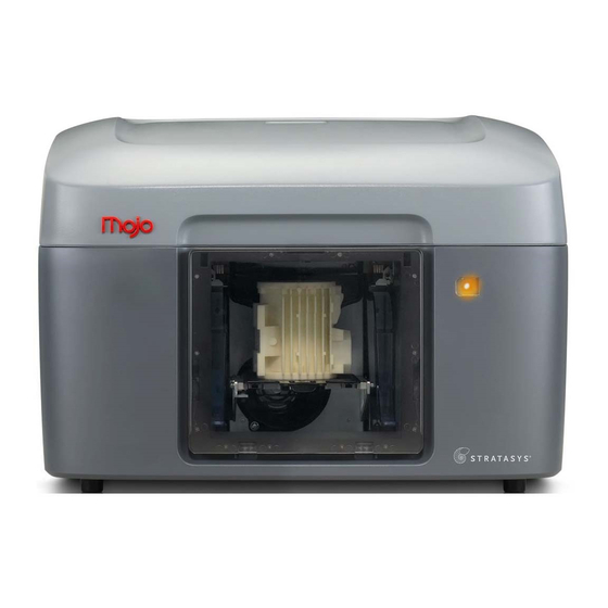
Print Wizard is the preprocessing software that runs on Windows 7 or Windows 8 platforms. Mojo builds a maximum part size of 127 x 127 x 127 mm (5 x 5 x 5 in.). Each QuickPack Print Engine contains 1311 cm³ (80 in³) of material and the extrusion head. - Page 9 Figure 2-1: Front and right side view of printer Cover Tip wipe assemblies Purge buckets Door Modeling base Platen Door sensor LED display...
- Page 10 Top view of printer Model material sensor Model head socket assembly Mojo QuickPack Print Engine - ABSplus Model material bay Bellows Support material bay Cover sensor Mojo QuickPack Print Engine - SR-30 support Support material sensor Support head socket assembly...
- Page 11 Figure 2-3: Left side of printer AC power cord connector Power ON/OFF switch...
- Page 12 Figure 2-4: Rear view of printer USB cable connector...
- Page 13 Figure 2-5: Mojo QuickPack Print Engines Handle Material tube guide Material tube Material container bag (do not remove) Locking tab Print head...
- Page 14 Startup supplies USB Cable Power cord (Euro) Power cord (US) Tip wipe assembly (2X) Modeling base (2X) Mojo Print Wizard Software Mojo 3D Printer Software Model Material Print Engine (Starter: 20 ci/328 ci) Support Material Print Engine (Starter: 8 ci/131 ci)
-
Page 15: Setup
3 SETUP Set up the printer using the setup instructions included with printer. CONNECTING THE SYSTEM Make sure the following preparations of the physical site are met: • The system must be placed on a flat and stable surface able to support 34.1 kg (75 lbs.) to avoid the risk of falling. - Page 16 The LED display will cycle through a test sequence. When complete the display will turn red. After communication has been established to the host computer, the display will turn green. The green LED indicates the printer is ready to build. Figure 3-9: LED test sequence...
-
Page 17: Installing Software
Loss of part will occur if this feature is not turned off. See Windows support and help instructions on how to turn these features off. The host computer is defined as the computer that is connected directly to the Mojo printer. There are two software programs that are required for the Mojo printer: •... -
Page 18: Print Wizard Software
Figure 3-11: Connecting the USB cable The software may take several minutes to load. PRINT WIZARD SOFTWARE Locate the Print Wizard Software CD from the startup supplies and insert into your computer or host computer CD drive. Follow the prompts to finish loading the Print Wizard software on your computer or host computer. -
Page 19: Operation
4 OPERATION LED DISPLAY The LED display indicates the status of the printer. Figure 4-13: LED display LED Display Status Idle/Build Door or cover open User/Pause Machine pause User Cancel Failure... -
Page 20: Printer Status Icons
PRINTER STATUS ICONS Icons show printer status in both 3D printer software and Print Wizard. Printer Icon Printer Status Discription Error Idle Disconnected Out of material Part done Paused Printing... -
Page 21: Print Wizard/3D Printer Software Overview
3D Printer software is installed on the host computer and is used to send files to the printer. • 3D Printer software only needs to be installed on the host computer. • Only one Mojo printer can be connected to the host computer. Figure 4-14: Network overview Print Wizard... -
Page 22: Installing A Modeling Base
INSTALLING A MODELING BASE Note: Re-use of modeling bases is not recommended. Hot Surface: The metal surfaces inside of the chamber can be hot. Use extra care when working around heated components. Always make sure there is a modeling base in the printer before printing a part. Install the modeling base by aligning the base tabs into the slots on the platen. -
Page 23: Processing Your Stl File For Printing
PROCESSING YOUR STL FILE FOR PRINTING OPENING PRINT WIZARD Create an STL file using your CAD software. Refer to your CAD software help section for more information about converting your CAD drawings into STL files. There are several ways of starting Print Wizard: •... -
Page 24: Adding Additional Printers
Obtain the host computer IP address from your network administrator. Enter the IP address of the host computer connected to the printer in the boxes provided, and then press OK or from the menu on the Mojo control panel on the host computer. -
Page 25: Selecting Support Style
SELECTING SUPPORT STYLE Supports are used to support the part during the build process. Supports are removed when the part is complete. Support styles will affect the support strength and build time of the print. SMART support is the default setting. -
Page 26: Selecting Part Interior
Display units can be selected for English or Metric measurement. The STL file selected will display the size of the part under the file name. Display units determines whether the part size is displayed in millimeters or inches. The unit selected will also be reflected in material information in the Mojo Control Panel window. Figure 4-21:... -
Page 27: Selecting The Orientation Of Your Part
SELECTING THE ORIENTATION OF YOUR PART The orientation function displays an expanded preview window that shows the orientation of the part when it prints. Orientation impacts build speed, part strength, surface finish and material consumption. Figure 4-22: Part orientation You can change the orientation of your part by clicking the Orient Part button and then selecting the orientation desired from the preview window. -
Page 28: Rotating The Part View
ROTATING THE PART VIEW Left click on the part and then drag the mouse to the left or right to rotate the view within the chamber. This will provide viewing of the front, left side, back, and right side views of the part(s) being printed. Figure 4-23: Rotating the view SELECTING THE SCALE OF YOUR PART... -
Page 29: Selecting The Number Of Copies
For example: a cube that is defined as 5.1 cm (2 in.) X 5.1 cm (2 in.) X 5.1 cm (2 in.) can be built to be 10.2 cm (4 in.) X 10.2 cm (4 in.) X 10.2 cm (4 in.) by simply changing the scale to 2. If after changing the scale to 2, you decide that a size of 7.6 cm (3 in.) X 7.6 cm (3 in.) X 7.6 cm (3 in.) would be preferred, change the scale to 1.5 - the scale relates to the original size of 2 inches, NOT the resulting 4 inches from the first scale change. -
Page 30: Job Creation
JOB CREATION Print Wizard automatically calculates the size and number of parts that can be printed on the modeling base. If the size and number of the part are too large, Print Wizard will add another job. The number of jobs created is based on: •... -
Page 31: Adding/Removing Parts
ADDING/REMOVING PARTS STL files can be added to the job by: • Double-clicking an STL file. • Using the drag-and-drop feature of Windows Explorer to move the file into the print window. By clicking the “+” sign. • Note: Once the STL file is brought into Print Wizard, the file is then considered a part. -
Page 32: Stl Part Content Information
STL PART CONTENT INFORMATION The name of the STL file and the quantity of parts to be printed for each job are displayed in the window. A thumbnail view of the individual part(s) for all jobs are displayed on the left hand side of the Print Wizard screen. Figure 4-29: Print Wizard screen PROCESSING THE PART... - Page 33 The following window will be displayed while processing the part. Figure 4-31: Processing The following window will display a list of all processed jobs along with time and material estimates. Processed parts can be later selected using the Control Panel select part drop-down menu. Figure 4-32: Processed parts list...
-
Page 34: Printing A Part From Mojo Control Panel
PRINTING A PART FROM MOJO CONTROL PANEL Once parts are processed in Print Wizard, they can then be printed using Mojo 3D printer software on the host computer. Open Mojo Control Panel and the window below appears. The following information is displayed: •... - Page 35 Click Select part from the drop down menu and select the part to be printed. The first processed part will be displayed in the preview window with the part name. Figure 4-34: Part selection Click Print to begin printing. Note: If there is not enough model or support material available in the QuickPack Print Engine to complete the part, the part will not print.
- Page 36 The following window will be display while the part is printing. Figure 4-36: Printing If the printer is paused, the following window will be displayed. Click Resume to continue printing. Figure 4-37: Paused...
-
Page 37: Control Panel Drop-Down Menu
If a printer fault occurs during printing, specific information will be displayed in the window. Refer to Troubleshooting in Section 6 for additional information. Figure 4-38: Fault CONTROL PANEL DROP-DOWN MENU The information icon provides a drop-down menu for additional printer functions. Figure 4-39: Control Panel Drop-Down Menu By clicking the Information Icon, a drop-down menu will appear with the following selections. -
Page 38: Attempt To Clear The Error
ATTEMPT TO CLEAR THE ERROR If certain errors occur, selecting “Attempt to clear the error” will clear the error and continue the printing process. Figure 4-40: Attempt to clear the error option EXPORT PRINTER FILE To better diagnose printer issues, you may need to export the printer configuration file (cfg) from your printer and send it to your Service Provider. -
Page 39: Ip Address
Figure 4-44: Maintenance Purge option Click on the printer information icon in the upper left of the Mojo Control Panel window. Select Maintenance Purge. Select either Model or Support to be purged. Wait for the liquefier to heat and purge to complete. -
Page 40: About Mojo Control Panel
ABOUT MOJO CONTROL PANEL Displays Control Panel version and build number. Figure 4-45: About Mojo Control Panel option REMOVING A COMPLETED PART When the job is complete, remove the part. Hot Surface: The surfaces inside of the chamber can be hot. Use extra care when working around heated components. -
Page 41: Remove A Part From The Modeling Base
REMOVE A PART FROM THE MODELING BASE After removing the modeling base from the printer, firmly flex the modeling base back and forth with your hands to loosen the part. Pull the part off of the modeling base or use a putty knife to completely remove the part. Note: Parts are easier to remove from the modeling base when they are still warm. -
Page 42: Removing Support Material
REMOVING SUPPORT MATERIAL Mojo uses soluble support material which is designed to dissolve in a water based solution. Your part is left with a smooth and clean finish with the fine details intact. The soluble support material can be removed by hand with relative ease, but is designed to be dissolved from your parts for hands free finishing. -
Page 43: Storing Quickpack Print Engine
STORING QUICKPACK PRINT ENGINE QuickPack Print Engines are best if used within one year from the date of manufacturing. The manufacturing date is printed on the QuickPack Print Engine bag. Always keep QuickPack Print Engines stored in a vertical position. Note: If an opened QuickPack Print Engine has not been used in over two weeks, two maintenance purges should be performed (see “Maintenance purge”... -
Page 44: Replacing The Quickpack Print Engine
REPLACING THE QUICKPACK PRINT ENGINE Remove the QuickPack Print Engine from its box. Tear open the bag containing the QuickPack Print Engine. Figure 4-50: Open Bag Remove the cardboard insert from the top of the QuickPack Print Engine outer bag. Figure 4-51: Remove cardboard inserts... - Page 45 Remove the plastic bag containing the tip wipe assembly from the QuickPack Print Engine handle. The tip wipe assembly will be installed in a later step. Figure 4-52: Removing Tip Wipe Assembly Bag Use the handle to remove the QuickPack Print Engine from the bag and remove the orange tape. Figure 4-53: Removing the QuickPack Print Engine Place the QuickPack Print Engine material in the appropriate bay.
- Page 46 Push down on the QuickPack Print Engine to release the locking tab. Figure 4-55: Release locking tab Open the appropriate head socket lid by squeezing the tabs together and lifting up. Figure 4-56: Open head socket (model head socket shown)
- Page 47 Open the appropriate material sensor lid by squeezing the tabs together and lifting up. Figure 4-57: Open material sensor lid (model material sensor shown) Unclip the head from the QuickPack Print Engine handle. Figure 4-58: Unclip the head...
- Page 48 Insert the head in the appropriate head socket and close the lid. Figure 4-59: Inserting the head (model head shown) Install the model material tube guide into the key in the model material sensor and close the lid. Install the support material tube guide into the key in the support material sensor and close the lid.
-
Page 49: Removing And Installing Tip Wipes
REMOVING AND INSTALLING TIP WIPES Note: Replace the tip wipe that corresponds to the QuickPack Print Engine (model or support) that is being replaced. Open the door. Remove the tip wipe assembly that corresponds to the QuickPack Print Engine being replaced by lifting the tip wipe up and out of the bracket. -
Page 50: Maintenance
5 MAINTENANCE PREVENTIVE MAINTENANCE DAILY EMPTY THE PURGE BUCKETS Empty the purge buckets after each build has completed. INSPECT THE TIP WIPE ASSEMBLY After each build you should inspect the tip wipe assembly to make sure there is no material build up. If there is material build up, clean the tip wipe assembly by brushing it off. -
Page 51: Troubleshooting
6 TROUBLESHOOTING GENERAL Many printer issues can be resolved by pressing Resume in Mojo Control Panel or by cycling power. CYCLING POWER Turn the printer power switch to the OFF position. The printer will shut off and the LED display will go blank. -
Page 52: Exporting Printer File
Service Provider. Figure 6-63: Export Printer File option Open Mojo Control Panel from the host computer. Click on the printer information icon in the upper left of the window. Select Export Printer File. Browse to the directory where you wish to save the configuration file (.cfg). -
Page 53: Troubleshooting
4. Reboot the host computer. “Cycling power” on page 45 5. If all three LEDs are blinking, cycle power (see 6. Reinstall Mojo 3D printer software. 7. Swap out the USB cable with another cable. Cannot read filament Make sure the material tube guides are installed correctly in the material sensor assemblies. -
Page 54: Warning/Fault Codes
Service Provider. FAULT CODE CHART Note: Fault codes will cause the part to stop building and the part cannot be recovered. Fault Codes Displayed in the Mojo Control Panel Code Name Recommendation Door open during build. Cycle power and restart part. -
Page 55: Warning Code Chart
WARNING CODE CHART Note: Warning codes will cause the printer to pause during a build. The build may be recovered by pressing Resume in Mojo Control Panel. Warning codes displayed in the Mojo Control Panel Code Name Recommendation Gantry has lost position. -
Page 56: Error Code Chart
Warning codes displayed in the Mojo Control Panel Code Name Recommendation Head fan current too low. Press Resume. If error persists, contact service provider. Loss of move commands to the Unplug and reconnect the USB cable printer. connection. Cycle power. - Page 57 2045 Printer firmware version is older Select the “Attempt to clear the error” menu than PC software version. item in the Mojo Control Panel to update printer firmware version to match the PC software version. (This takes approximately 2 minutes.)
-
Page 58: Support
System serial number. System software build number. • • Mojo 3D Printer software and Print Wizard software version numbers. • Detailed description of the problem you are experiencing. If possible, try to be near the printer for troubleshooting, if possible. -
Page 59: Recycling
8 RECYCLING Recycle all materials per your local recycling guidelines. Visit http://www.stratasys.com/recycle for information on recycling QuickPack Print Engines in your region. Figure 8-64: Recycling Codes System Component Materials Recycling Code Modeling bases All packaging materials can be recycled per your local recycling guidelines. -
Page 60: Printer Specifications
50.8 mm (2 in.) minimum space around printer for air circulation. WORKSTATION SPECIFICATIONS For details, see the Print Wizard and Control Panel Workstation Requirements document available from the Stratasys website. POWER SPECIFICATIONS Source (nominal) 6A 100-127VAC or 2.5A @ 220-240VAC -- 50/60Hz 600W dedicated circuit within 2 m (80 in.) -
Page 61: Environmental Specifications
ENVIRONMENTAL SPECIFICATIONS The Mojo printer is intended for indoor use only. ° ° ° ° Operating temperature range C to 30 C (59 F to 86 Relative humidity range 30 to 70 percent, non condensing Altitude Shall not exceed 6561.68 feet (2000 m) -
Page 62: Supplemental Information
Rules. Caution: Pursuant to Part 15.21 of the FCC Rules, any changes or modifications to this equipment not expressly approved by Stratasys, ltd. may cause harmful interference and void the FCC authorization to operate this equipment. Note: This equipment has been tested and found to comply with the limits for a Class A digital device, pursuant to Part 15 of the FCC Rules. -
Page 63: Canada Electromagnetic Compatibility (Emc)
Radio Interference Regulations of the Canadian Department of Communications. MSDS (MATERIAL SAFETY DATA SHEET) You can obtain current Material Safety Data Sheets for the material used in the printer by visiting: www.stratasys.com/materials/material-safety-data-sheets. DISPOSAL OF WASTE EQUIPMENT BY USERS IN PRIVATE HOUSEHOLDS IN THE EUROPEAN UNION This symbol on the product or on its packaging indicates that this product must not be disposed of with your other household waste. -
Page 64: Glossary
GLOSSARY OF TERMS HOST COMPUTER The host computer is defined as the computer where the Mojo 3D printer software and optional Print Wizard software reside. The host computer is directly connected to the Mojo printer through a USB cable. One or more files that have been sent to a Mojo printer. - Page 65 Customers, resellers, and Stratasys employees are encouraged to send comments about our documentation and training to c-support@stratasys.com. We greatly value your comments, review all of them, and use them to improve subsequent releases of the documentation. In your email message please include the document title, part number (located on the front cover), and page number.
Need help?
Do you have a question about the Mojo and is the answer not in the manual?
Questions and answers