D-Link DFL-500 User Manual
Hide thumbs
Also See for DFL-500:
- Manual (122 pages) ,
- User manual (114 pages) ,
- Quick install manual (8 pages)
Table of Contents

Related Manuals for D-Link DFL-500


Summary of Contents for D-Link DFL-500
-
Page 1: User Manual
DFL-500 V2.27 User Manual D-Link Systems, Inc. DFL-500 User Manual... - Page 2 © Copyright 2002 D-Link Systems, Inc. All rights reserved. No part of this publication including text, examples, diagrams or illustrations may be reproduced, transmitted, or translated in any form or by any means, electronic, mechanical, manual, optical or otherwise, for any purpose, without prior written permission of D-Link Systems, Inc.
-
Page 3: Table Of Contents
Reconnecting to the web-based manager ....................21 Using the command line interface ........................ 21 Connecting to the CLI ..........................21 Configuring the DFL-500 to run in NAT/Route mode ................21 Connecting to your network .......................... 22 Configuring your internal network ......................... 23 Completing the configuration ........................ - Page 4 Reconnecting to the web-based manager ....................26 Using the command line interface ........................ 26 Connecting to the CLI ..........................26 Configuring the DFL-500 to run in Transparent mode................27 Setting the date and time ..........................28 Connecting to your network .......................... 28 Firewall configuration.................
- Page 5 IPSec client to network pass through ....................... 70 IPSec network to network pass through ....................72 PPTP and L2TP VPNs ................. 75 PPTP VPN configuration..........................75 Configuring the DFL-500 as a PPTP gateway..................76 Configuring a Windows 98 client for PPTP....................77 DFL-500 User Manual...
- Page 6 PPTP pass through............................79 PPTP client to network pass through ....................... 80 L2TP VPN configuration ..........................81 Configuring the DFL-500 as an L2TP gateway ..................81 Configuring a Windows 2000 Client for L2TP................... 82 Configuring a Windows XP Client for L2TP....................83 RADIUS authentication for PPTP and L2TP VPNs ..................
- Page 7 Upgrading the DFL-500 firmware ......................108 Manual antivirus database updates ......................111 Manual attack database updates......................111 Displaying the DFL-500 serial number ....................112 Backing up system settings ........................112 Restoring system settings........................112 Restoring system settings to factory defaults ..................113 Restarting the DFL-500 ..........................
- Page 8 Troubleshooting FAQs ................131 General administration..........................131 Network configuration ..........................131 Firewall policies............................131 Schedules ..............................132 VPN................................132 Virus protection ............................132 Web content filtering ........................... 133 Logging ............................... 133 Technical Support..................134 Limited Warranty..................137 Registration ....................140 DFL-500 User Manual...
-
Page 9: Introduction
Your DFL-500 NPG is a dedicated easily managed security device that delivers a full suite of capabilities that include: ·... -
Page 10: Web Content Filtering
If a match is found between a URL on the URL block list, or if a web page is found to contain a word or phrase in the content block list, the DFL-500 blocks the web page. The blocked web page is replaced with a message that you can edit using the DFL-500 web-based manager. -
Page 11: Transparent Mode
Transparent Mode is used to provide firewall protection to a pre-existing network with public addresses. The internal and external network interfaces of the DFL-500 can be in the same network; therefore, the DFL-500 can be inserted into your network at any point without the need to make any changes to your network. -
Page 12: Secure Installation, Configuration, And Management
Installation is quick and simple. When you initially power the DFL-500 up, it is already configured with default IP addresses and security policies. All that is required for the DFL-500 to start protecting your network is to connect to the web-based manager, set the operating mode and use the setup wizard to customize DFL-500 IP addresses for your network. -
Page 13: About This Document
Logs can be sent to a remote syslog server or to a WebTrends server using the WebTrends enhanced log format. About this document This user manual describes how to install and configure the DFL-500. This document contains the following information: ·... -
Page 14: Customer Service And Technical Support
Customer service and technical support For firmware, attack database, and antivirus database updates, updated product documentation, technical support information, and other resources, please visit our web site at http://www.D-Link.com and follow the link to the support page. The D-Link automatic update center at update.D-Link.com is also available for automatically updating your antivirus and attack databases. -
Page 15: Getting Started
Registration Card DFL-500 package contents Mounting The DFL-500 can be installed on any stable surface. Make sure the appliance has at least 1.5 in. (3.75 cm) of clearance on each side to allow for adequate air flow and cooling. Dimensions ·... -
Page 16: Powering On
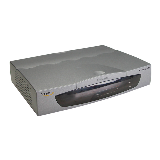
· Connect the AC adapter to a power outlet. The DFL-500 starts up. The Power and Status lights light. The Status light flashes while the DFL-500 is starting up and remains lit when the system is up and running. DFL-500 LED indicators... -
Page 17: Next Steps
Front and back view of the DFL-500 Next steps Now that your DFL-500 is up and running, you can proceed to configure it for operation: · If you are going to run your DFL-500 in NAT/Route mode, go to NAT/Route mode installation ·... -
Page 18: Nat/Route Mode Installation
NAT/Route mode installation This chapter describes how to install your DFL-500 in NAT/Route mode. If you want to install the DFL-500 in Transparent mode, see Transparent mode installation. This chapter includes: · Preparing to configure NAT/Route mode · Using the setup wizard ·... -
Page 19: Advanced Nat/Route Mode Settings
_____._____._____._____ Ending IP: _____._____._____._____ Netmask: _____._____._____._____ DHCP Server Settings: Default Route: _____._____._____._____ DNS IP: _____._____._____._____ The DFL-500 contains a DHCP server that you can configure to automatically set the addresses of the computers on your internal network. DFL-500 User Manual... -
Page 20: Using The Setup Wizard
Set the IP address of the computer with an ethernet connection to the static IP address 192.168.1.2 and a netmask of 255.255.255.0. · Using the crossover cable or the ethernet hub and cables, connect the Internal interface of the DFL-500 to the computer ethernet connection. ·... -
Page 21: Reconnecting To The Web-Based Manager
IP address. Browse to https:// followed by the new IP address of the internal interface. Otherwise, you can reconnect to the web-based manager by browsing to https://192.168.1.99. You have now completed the initial configuration of your DFL-500, and you can proceed to connect the DFL- 500 to your network using the information in Connecting to your network. -
Page 22: Connecting To Your Network
Confirm that the addresses are correct. Enter: get system interface The CLI lists the IP address and netmask settings for each of the DFL-500 interfaces as well as the mode of the external interface (Manual, DHCP, or PPPoE). Configure the NAT/Route mode default gateway ·... -
Page 23: Configuring Your Internal Network
If you are using the DFL-500 as the DHCP server for your internal network, configure the computers on your internal network for DHCP. Use the internal address of the DFL-500 as the DHCP server IP address. -
Page 24: Transparent Mode Installation
Transparent mode installation This chapter describes how to install your DFL-500 in Transparent mode. If you want to install the DFL-500 in NAT/Route mode, see NAT/Route mode installation. This chapter includes: · Preparing to configure Transparent mode · Using the setup wizard ·... -
Page 25: Using The Setup Wizard
Type admin in the Name field and select Login. DFL-500 login page Changing to Transparent mode The first time you connect to the DFL-500 it is configured to run in NAT/Route mode. To switch to Transparent mode using the web-based manager: ·... -
Page 26: Starting The Setup Wizard
IP default gateway field. Using the command line interface As an alternative to the setup wizard, you can configure the DFL-500 using the Command Line Interface (CLI). To connect to the DFL-500 command line interface (CLI) you require: ·... -
Page 27: Configuring The Dfl-500 To Run In Transparent Mode
<IP Address> Example set system manageip gateway 192.168.1.20 You have now completed the initial configuration of the DFL-500 and you can proceed to connect the DFL-500 to your network using the information in Connecting to your network that follows. -
Page 28: Setting The Date And Time
For effective scheduling and logging, the DFL-500 date and time should be accurate. You can either manually set the time or you can configure the DFL-500 to automatically keep its time correct by synchronizing with a Network Time Protocol (NTP) server. -
Page 29: Firewall Configuration
(port number). For the packet to be connected through the DFL-500, you must have added a policy to the interface that receives the packet. The policy must match the packet's source address, destination address, and service. -
Page 30: Transparent Mode
Select Transparent Mode to provide firewall protection to a network with public addresses. There are no restrictions on the addresses of the interfaces of the DFL-500. Therefore, the DFL-500 can be inserted into your network at any point without the need to make changes to your network. In transparent mode, the DFL- 500 acts like a router. -
Page 31: Adding Policies
Click Apply. Adding policies Add security policies to control connections and traffic between DFL-500 interfaces. The first step to adding a policy is to select a policy list. There are 2 policy lists: Int to Ext Policies for connections from the internal network to the external network (the Internet). -
Page 32: Adding Nat Mode Policies
A virtual IP must be added to Ext to Int NAT mode policies. For more information about virtual IPs, see Adding virtual IPs. To add a NAT mode policy: · Go to Firewall > Policy . · Select a policy list tab. · Select New to add a new policy. DFL-500 User Manual... - Page 33 Select OK to add the policy. The policy is added to the selected policy list. You must arrange policies in the policy list so that they have the results that you expect. See Ordering policies in policy lists for more information. DFL-500 User Manual...
-
Page 34: Editing Policies
When the DFL-500 receives a connection attempt at an interface, it must match the connection attempt to a policy in either the Int to Ext or Ext to Int policy list. The DFL-500 starts at the top of the policy list for the... -
Page 35: Adding Addresses
These addresses must be valid addresses for the network connected to that interface. By default the DFL-500 includes two addresses that cannot be edited or deleted: ·... -
Page 36: Editing Addresses
The name can contain numbers (0-9) and upper and lower case letters (A-Z, a-z), and the special characters - and _. Other special characters and spaces are not allowed. · In the IP Address field, enter the IP address of the server on the internal network. DFL-500 User Manual... -
Page 37: Services
For example, if the virtual IP is for a web server the IP address must be a static IP address obtained from your ISP for your web server and must not be the same as the external address of the DFL-500. However, your ISP must route this address to the external interface of the DFL-500. -
Page 38: Providing Access To Custom Services
To add a custom service: · Go to Firewall > Service > Custom . · Select New. · Enter a Name for the service. This name appears in the service list used when you add a policy. DFL-500 User Manual... -
Page 39: Grouping Services
PC, connections to be accepted by the DFL-500. Adding this service to an Ext to Int policy would allow a user on the Internet to use pcAnywhere to connect to one or more computers on the internal network. -
Page 40: Schedules
· Type in a name for the schedule. The name can contain numbers (0-9) and upper and lower case letters (A-Z, a-z), and the special characters - and _. Other special characters and spaces are not allowed. DFL-500 User Manual... -
Page 41: Creating Recurring Schedules
Select the days of the week that are working days. · Set the Start Hour and the End Hour to the start and end of the work day. Note: Recurring schedules use the 24-hour clock. · Select OK. DFL-500 User Manual... -
Page 42: Adding A Schedule To A Policy
Arranging a one-time schedule in the policy list to deny access Users and authentication You can configure the DFL-500 to require users to authenticate (enter a user name and password) to access HTTP, FTP, or Telnet services through the firewall. To configure authentication you need to add user names and passwords to the firewall and then add policies that require authentication. -
Page 43: Adding User Names And Passwords
Once you have added users and passwords to the firewall, you can include authentication in policies. You can add authentication when you create the policy or you can edit existing policies and change action to AUTH. To add authentication to a policy: · Go to Firewall > Policy . DFL-500 User Manual... -
Page 44: Port Forwarding
Port forwarding routes packets that are received by the DFL-500 external interface according to the packet's destination service port. When the packet is intercepted, the firewall changes the packet's destination address to an address on the network connected to the internal interface. The DFL-500 then forwards the packet to the server at that address. -
Page 45: Ip/Mac Binding
IP/MAC binding protects the DFL-500 from IP Spoofing attacks. IP Spoofing attempts to use the IP address of a trusted computer to access the DFL-500 from a different computer. The IP address of a computer can easily be changed to a trusted address, but MAC addresses are added to ethernet cards at the factory and cannot easily be changed. -
Page 46: Adding Ip/Mac Binding Addresses
MAC address or it is blocked. Block traffic when The DFL-500 blocks all traffic with a source address that is not found in the IP/MAC binding table. not defined in the Any traffic with a source address that is defined in the IP/MAC binding table must have the table correct MAC address or it is also blocked. - Page 47 Less important services should be assigned a low priority. The firewall provides bandwidth to low priority connections only when bandwidth is not needed for high priority connections. · Select OK to save your changes to the policy. DFL-500 User Manual...
-
Page 48: Example Policies
The following example route mode policy to accept connections from the Internet and forward them to the internal network is similar to any route mode policy. In this example, the DFL-500 is running in NAT/Route mode and the mode for connections between the external and internal interfaces has been changed to route mode. -
Page 49: Transparent Mode Policy For Public Access To A Server
Policies that deny connections from the Internet can control access to policies that accept connections from the Internet. You can deny connections: · From specific Internet addresses · To specific internal addresses · To specific services · According to a one-time or recurring schedule DFL-500 User Manual... -
Page 50: Using A Schedule To Deny Access
Internet is similar to any procedure to deny a connection that would otherwise be accepted by the default policy. In this example, the DFL-500 is running in NAT/Route mode. To deny a connection to the Internet: ·... -
Page 51: Adding Policies That Accept Connections
The following example procedure to accept connections from the internal network to the Internet is similar to any procedure to accept connections. In this example, the DFL-500 is running in NAT/Route mode. To accept a connection to the Internet: ·... -
Page 52: Requiring Authentication To Connect To The Internet
According to a schedule The following example procedure requiring users on the internal network to authenticate to access HTTP servers on the Internet is similar to any procedure requiring authentication. In this example, the DFL-500 is running in NAT/Route mode. -
Page 53: Ipsec Vpns
VPN client to create a secure tunnel between their computer and an office private network. The DFL-500 is an excellent choice for connecting a satellite office or a telecommuter to a main office VPN. Usually the main office would be protected by a high-capacity product such as the DFL-500-300. The small office requires the same security and functionality but the smaller user base makes the DFL-500 the product of choice for protecting smaller networks. -
Page 54: Autokey Ipsec Vpn Between Two Networks
DFL-500 product that supports more users, such as the DFL-500-300. You can also use the DFL-500 to connect to a network protected by a third-party VPN gateway that supports IPSec and Autokey IKE. -
Page 55: Creating The Vpn Tunnel
Enter up to 20 characters. The key must be the same on Authentication both VPN gateways and should only be known by network ddcHH01887d ddcHH01887d administrators. Select Incoming NAT if you require Network address Incoming NAT Select Select translation for VPN packets. DFL-500 User Manual... - Page 56 During the second phase (P2) the VPN gateways negotiate to select a common algorithm for data communication. When you select algorithms for the P2 Proposal, you are selecting the algorithms that the DFL-500 will propose during Phase 2 negotiation. Again, during P2, each VPN gateway must have at least one algorithm in common.
-
Page 57: Adding Source And Destination Addresses
The name to assign to the destination address to be connected to Branch_Office Main_Office Name using the VPN. The destination IP address and netmask of the network at the far 192.168.2.0 192.168.1.0 address d f th VPN t DFL-500 User Manual... -
Page 58: Adding An Ipsec Vpn Policy
The destination address that you added for the Branch_Office Main_Office Address (See IPSec Autokey VPN addresses). The name of the VPN tunnel that you created for VPN Tunnel Branch_Office_VPN Branch_Office_VPN the VPN (See Example IPSec Autokey VPN DFL-500 User Manual... -
Page 59: Autokey Ipsec Vpn For Remote Clients
Communication between the remote client and the internal network takes place over an encrypted VPN tunnel that connects the remote client to the DFL-500 VPN gateway across the Internet. Once connected to the VPN, the remote client computer seems to be installed on the internal network. -
Page 60: Configuring The Network End Of The Vpn Tunnel
To accept connections from a client at a static IP address (for example, 2.2.2.2). 2.2.2.2 Gateway Select the Encryption algorithms to propose for Phase 1 of the IPSec VPN DES and P1 Proposal connection. See About P1 and P2 proposals. 3DES DFL-500 User Manual... -
Page 61: Adding Source And Destination Addresses
Select OK to save the Autokey IKE VPN tunnel. Adding source and destination addresses The next step in configuring the DFL-500 VPN gateway is to add the source and destination addresses for the VPN policy. For each client VPN tunnel you require two addresses: ·... -
Page 62: Adding An Ipsec Vpn Policy
The IP address and netmask of a VPN client with a static IP address (for example, 2.2.2.2). Netmask 255.255.255.255 Complete the following procedures on the DFL-500 VPN gateway to add the source and destination addresses. Adding a source address To add the source address to the internal address list: ·... -
Page 63: Configuring The Ipsec Vpn Client
The VPN client PC must be running industry standard IPSec Autokey IKE VPN client software. D-Link recommends the SafeNet/Soft-PK client from IRE, Inc. Configure the client as required to connect to the DFL-500 VPN gateway using an IPSec VPN configuration. Make sure the client configuration includes the settings in VPN client configuration. -
Page 64: Adding A Dial-Up Vpn Tunnel
Select the encryption and authentication algorithms to propose for Phase 2 of the IPSec VPN P2 Proposal connection. See About P1 and P2 proposals. Select Enable replay detection to prevent IPSec replay attacks. See About replay Select detection DFL-500 User Manual... -
Page 65: Configuring Remote Ipsec Vpn Clients
Configuring remote IPSec VPN gateways The remote IPSec VPN gateways must be DFL-500 IPSec VPN gateways or third-party IPSec VPN gateways running industry standard IPSec Autokey IKE VPN software. Configure the VPN gateway as required to connect to the dial-up VPN gateway using an IPSec VPN configuration. -
Page 66: Viewing Vpn Tunnel Status
Go to VPN > IPSEC > Dial-up Monitor . The Local IP column is always set to 0.0.0.0/0.0.0.0. The Local Gateway column displays the IP address of the DFL-500 external interface. The Remote Gateway column displays the IP address of the remote VPN gateway or remote IPSec VPN client connected to the tunnel. -
Page 67: Manual Key Ipsec Vpn Between Two Networks
Manual key IPSec VPN between two networks DFL-500 IPSec VPNs can be configured to use Autokey IKE or manual key exchange. In most cases Autokey key exchange is preferred because it is easier to configure and maintain. However, manual key exchange may be necessary in some cases for compatibility with third party VPN products. -
Page 68: Manual Key Ipsec Vpn For Remote Clients
Manual key exchange VPNs do not support VPN clients with dynamic IP addresses. The VPN client PC must have industry standard IPSec VPN client software installed. The DFL-500 VPN is based on the industry standard IPSec implementation of VPN making it interoperable with other IPSec VPN... -
Page 69: Configuring The Vpn Tunnel
Configure IPSec pass through so that users on your internal network can connect to an IPSec VPN gateway on the Internet. IPSec pass through allows IPSec connections to pass through your DFL-500 and connect to the destination IPSec VPN gateway. The DFL-500 performs address translation on the connection, so that it seems to the destination VPN gateway that the connection to its VPN is originating from the external interface of your DFL-500. -
Page 70: Ipsec Client To Network Pass Through
Other than enabling IPSec pass through, no special configuration is required for the DFL-500 that will be passed through. The VPN tunnel configuration of the VPN gateway on the Internet (or remote side) must be changed to accept connections from the IP address of the external interface of the DFL-500 that will be passed through. - Page 71 The administrator of the remote IPSec VPN gateway creates a standard VPN gateway configuration. However, the remote gateway address of the VPN tunnel is set to the external address of the DFL-500 to be passed through, rather than the IP address of the VPN client. Using the example in...
-
Page 72: Ipsec Network To Network Pass Through
IPSec pass through allows the DFL-500 internal IPSec VPN gateway to connect to the DFL-500-400 Internet IPSec VPN gateway. You can substitute any suitable DFL-500 product for the IPSec VPN gateways. One or both of these IPSec VPN gateways could also be a third-party VPN gateway. - Page 73 192.168.2.0 with a netmask of 255.255.255.0. The remote gateway address of the VPN tunnel is set to the external address of the DFL-500 to be passed through, rather than the external IP address of the internal IPSec VPN gateway. Using the example in...
- Page 74 Internet IPSec VPN gateway, the DFL-500 accepts IPSec VPN connections from the internal network and performs network address translation on them. The VPN packets are forwarded to the destination IPSec VPN gateway with a source address of the external interface of the DFL-500. DFL-500 User Manual...
-
Page 75: Pptp And L2Tp Vpns
RADIUS authentication for PPTP and L2TP VPNs PPTP VPN configuration You configure your DFL-500 to support PPTP by adding PPTP users and specifying a PPTP address range. You can also require PPTP VPN users to authenticate to your RADIUS server. Finally, to connect to the PPTP VPN, your remote Windows clients must be configured for PPTP. -
Page 76: Configuring The Dfl-500 As A Pptp Gateway
PPTP VPN between a Windows client and the DFL-500 Configuring the DFL-500 as a PPTP gateway Use the following procedure to configure the DFL-500 to be a PPTP gateway: · Go to VPN > PPTP > PPTP User . ·... -
Page 77: Configuring A Windows 98 Client For Pptp
Use the following procedure to configure a client machine running Windows 98 so that it can connect to a DFL-500 PPTP VPN. To configure the Windows 98 client, you must install and configure windows dial-up networking and virtual private networking support. -
Page 78: Configuring A Windows 2000 Client For Pptp
For Network Connection Type, select Connect to a private network through the Internet and select Next. · For Destination Address, enter the external address of the DFL-500 to connect to and select Next. · Set Connection Availability to Only for myself and select Next. -
Page 79: Pptp Pass Through
· In the VPN Server Selection dialog, enter the external IP address or hostname of the DFL-500 to connect to and select Next. · Select Finish. Configure the VPN connection · Right-click the icon that you have created. · Select Properties > Security . -
Page 80: Pptp Client To Network Pass Through
Configuring a Windows 2000 Client for PPTP Configuring a Windows XP Client for PPTP · Set the default gateway of the PPTP VPN client computer to the internal interface of the DFL-500 to be passed through. · Configure the PPTP VPN gateway. See Configuring the DFL-500 as a PPTP gateway. -
Page 81: L2Tp Vpn Configuration
DFL-500. The DFL-500 then forwards the PPTP packets to the PPTP VPN gateway. L2TP VPN configuration Configuring L2TP is similar to configuring PPTP. You configure the DFL-500 to support L2TP by adding L2TP users and specifying an L2TP address range. You can also require L2TP VPN users to authenticate to your RADIUS server. -
Page 82: Configuring A Windows 2000 Client For L2Tp
For Network Connection Type, select Connect to a private network through the Internet and select Next. · For Destination Address, enter the external address of the DFL-500 to connect to and select Next. · Set Connection Availability to Only for myself and select Next. -
Page 83: Configuring A Windows Xp Client For L2Tp
This user name and password is not the same as your VPN user name and password. Configuring a Windows XP Client for L2TP Use the following procedure to configure a client machine running Windows XP so that it can connect to a DFL-500 L2TP VPN. Configuring an L2TP VPN dial-up connection ·... - Page 84 · If the Public Network dialog box appears, choose the appropriate initial connection and select Next. · In the VPN Server Selection dialog, enter the external IP address or hostname of the DFL-500 to connect to and select Next. ·...
-
Page 85: Radius Authentication For Pptp And L2Tp Vpns
PPTP or L2TP user connects to a DFL-500, the user name and password is checked against the DFL-500 PPTP or L2TP user name and password list. If a match is not found locally, the DFL-500 contacts the RADIUS server for authentication. -
Page 86: Turning On Radius Authentication For Pptp
Turning on RADIUS authentication for L2TP RADIUS authentication can be turned on separately for PPTP and L2TP. To turn on RADIUS authentication for L2TP users: · Go to VPN > L2TP > L2TP Range . · Check Enable RADIUS. · Select Apply. DFL-500 User Manual... -
Page 87: Network Intrusion Detection System (Nids)
Network Intrusion detection system (NIDS) The DFL-500 NIDS is a real-time network intrusion detection sensor that can identify a wide variety of suspicious network traffic including direct attacks, and take action as required. The NIDS uses attack signatures, stored in the attack database, to identify common attacks. In response to an attack, the NIDS protects the DFL-500 and the networks connected to it by: ·... -
Page 88: Exploits
IP, TCP, UDP, and ICMP traffic. For maximum protection, you can turn on checksum verification for all types of traffic. However, if the DFL-500 does not need to do checksum verification, you can turn it off for some or all types of traffic to improve performance. You may not need to run checksum verifications if your DFL-500 is installed behind a router that also does checksum verification. -
Page 89: Viewing The Attack List
Check the channel to use for reporting alerts. In this release, you can select Log to record alerts on the attack log and Email to send alerts in Alert emails. SNMP will be available in a future release. · For Message, select Summary or Full. DFL-500 User Manual... - Page 90 · For Address Obfuscation, check source address, destination address, or both. When sending an alert message, the NIDS replaces the checked IP addresses of attacks with xxx.xxx.xxx.xxx. · Select Apply to save your changes. NIDS alerts configuration DFL-500 User Manual...
-
Page 91: Virus Protection
Blocking target files is also the only protection available from a virus that is so new that no effective virus scanner protects against it. You would not normally run the DFL-500 with blocking turned on. However, it is available for extremely high risk situations where there is no other way to prevent viruses from entering your network. -
Page 92: Antivirus Connection Types
Enable antivirus protection for IPSec VPN traffic that matches the antivirus connection type that Protection you are configuring. Settings Select Scan or Block. Scan DFL-500 antivirus protection extracts the following files from the protocol data stream and scans DFL-500 User Manual... -
Page 93: Worm Protection
Block deletes target files from the protocol data stream. By default selecting block causes the Block DFL-500 to delete all target files. Configure file blocking by selecting Detail. Detail Select Detail to configure the file types to block. You can block any of the file types listed above. -
Page 94: Customize Antivirus Messages
Customize antivirus messages Use the following procedures to customize the message that appears when DFL-500 antivirus protection removes a file from a content protocol stream. · Customizing messages added to email · Customizing messages added to web pages Customizing messages added to email To configure the messages added to email: ·... -
Page 95: Updating Your Antivirus Database
This database is continuously updated by D-Link as new viruses and worms are encountered and defined. You should keep your antivirus database up to date so that the DFL-500 can protect your network from new viruses. You can configure the DFL-500 to update the antivirus database automatically, or you can update your antivirus database manually. -
Page 96: Web Content Filtering
Block web pages that contain unwanted content by enabling content blocking and then creating a list of banned words and phrases. The DFL-500 blocks access to all web content that contains any of the banned words or phrases received at any interface. -
Page 97: Temporarily Disabling The Banned Word List
· Type a banned word or phrase. If you type a single word (for example, banned ), the DFL-500 blocks all web pages that contain that word. If you type a phrase (for example, banned phrase ), the DFL-500 blocks web pages that contain both of the words. -
Page 98: Clearing The Banned Word List
The DFL-500 downloads the banned word list to a text file on the management computer. You can specify a location to which to download the text file as well as a name for the text file. -
Page 99: Enabling The Url Block List
Select Enable URL Block to turn on URL blocking. The DFL-500 now blocks web pages added to the URL block list. Changing the URL block message To customize the message that users receive when the DFL-500 blocks web pages. · Go to Web Filter > URL Block . -
Page 100: Temporarily Disabling The Url Block List
You can also select Uncheck All to uncheck all of the items in the URL block list. All unchecked items in the URL block list are not blocked by the DFL-500. Clearing the URL block list To remove all of the URLs from the URL block list: ·... -
Page 101: Uploading A Url Block List
Uploading a URL block list You can create a URL block list in a text editor and then upload the text file to the DFL-500. Add one URL to each line of the text file. You can follow the URL with a space and then a 1 to enable or a zero (0) to disable the URL. - Page 102 DFL-500 User Manual...
-
Page 103: Logging And Reporting
· Selecting what to log Recording logs on a remote computer Use the following procedure to configure the DFL-500 to record logs onto a remote computer. The remote computer must be configured with a syslog server. · Go to Log&Report > Log setting . -
Page 104: Selecting What To Log
Select Apply to save your log settings. Log message formats The DFL-500 Traffic logs, Event logs, and Attack logs all have their own message format. All of these message formats are compatible with the WebTrends Enhanced Log Format (WELF). Use the information in the following sections to interpret DFL-500 log messages: ·... -
Page 105: Event Log Message Format
Each event log message records the date and time of the event and a description of the event. For connections to the DFL-500 for management and for configuration changes, the event log message also includes the IP address of the management computer. -
Page 106: Attack Log Message Format
2002 Jun 19 15:35:09 type=vpn, msg="Initiator: tunnel 172.18.0.1/172.16.0.1 main mode phase I succeeded" Attack log message format Attack logs record attacks intercepted by the DFL-500 NIDS (see Network Intrusion detection system (NIDS)). Each attack log message records the date and time at which the attack was made, the type of attack, and the source and destination IP addresses of the attack. -
Page 107: Administration
Make sure the computer from which you are going to connect to the web-based manager is correctly configured on the same network as the DFL-500 interface to which you are going to connect. · If the DFL-500 is running in NAT mode, connect to an interface that is configured for HTTPS management DFL-500 User Manual... -
Page 108: System Status
If you log onto the web-based manager with any other administrator account you can go to System > Status to view the system settings including: · Displaying the DFL-500 serial number All administrative users can also go to System > Status > Monitor and view DFL-500 system status. · System status monitor Upgrading the DFL-500 firmware D-Link releases new versions of the DFL-500 firmware periodically. - Page 109 Use the following procedure to upgrade the DFL-500 firmware using the CLI. To run this procedure you must install a TFTP server and be able to connect to this server from the DFL-500 internal interface. The TFTP server should be on the same subnet as the internal interface. You can download a free TFTP server from: http://site.ifrance.com/freewares/P_tftpd32.htm.
- Page 110 The following message appears: Enter TFTP Server Address [192.168.1.168]: You only have 3 seconds to press any key. If you do not press any key soon enough the DFL-500 reboots and you must log in and repeat the execute reboot command.
-
Page 111: Manual Antivirus Database Updates
Enter File Name [image.out]: · Enter the firmware image file name and press Enter. The TFTP server uploads the firmware image file to the DFL-500 and messages similar to the following appear: Total 7682959 Bytes Data Is Downloaded. Testing The Boot Image Now. -
Page 112: Displaying The Dfl-500 Serial Number
Displaying the DFL-500 serial number · Go to System > Status . The Serial number is displayed in the Status window. The serial number is specific to your DFL-500 and does not change with firmware upgrades. Backing up system settings This procedure does not back-up the Web content and URL filtering lists. -
Page 113: Restoring System Settings To Factory Defaults
Use the following procedure to restore system settings to the values set at the factory. This procedure does not change the DFL-500 firmware version or the Antivirus database. This procedure deletes all of the changes that you have made to the DFL-500 configuration and reverts the system to its original configuration including resetting interface addresses. -
Page 114: Automatic Antivirus And Attack Database Updates
The DFL-500 writes a message to the event log when it checks for database updates and when it downloads a new version of a database. You can also go to System > Update to see the date and time at which the antivirus and attack databases were last updated. -
Page 115: Network Configuration
At any time, you can go to System > Update and select Update Now to check for and update your antivirus and attack databases. Configuring automatic antivirus and attack database updates Network configuration Go to System > Network to make any of the following changes to the DFL-500 network settings: · Configuring the internal interface ·... -
Page 116: Configuring The External Interface
Go to System > Network > Interface . · For the external interface, select Modify · Set Addressing Mode to Manual. · Change the IP address and Netmask as required. · Select OK to save your changes. DFL-500 User Manual... - Page 117 · Select OK. The DFL-500 attempts to contact a DHCP server from the external interface to set the external IP address, netmask, and default gateway IP address. When the DFL-500 gets this information from the DHCP server, the new addresses and netmask are displayed in the IP address and Netmask fields. These fields are colored grey to indicate that the addresses have not been assigned manually.
- Page 118 DFL-500 transmits from its external interface. Ideally, you want this MTU to be the same as the smallest MTU of all the networks between the DFL-500 and the Internet. If the packets the DFL- 500 sends are larger, they get broken up or fragmented, which slows down transmission speeds.
-
Page 119: Configuring The Management Interface (Transparent Mode)
If there are multiple routers installed on your network, you can configure static routes to determine the path that data follows over your network before and after it passes through the DFL-500. You can also use static routing to allow different IP domain users to access the Internet through the DFL-500. -
Page 120: Providing Dhcp Services To Your Internal Network
Select External Interface to enable RIP server support from the external interface. Providing DHCP services to your internal network If it is operating in NAT mode, you can configure the DFL-500 to be the DHCP server for your internal network: ·... -
Page 121: System Configuration
To configure the DFL-500 to use NTP, select Synchronize with NTP server. By default, the DFL-500 is configured to connect to an NTP server at IP address 192.5.5.250, which is the IP address of an NTP server maintained by the Internet Software Consortium at Palo Alto, CA, USA. -
Page 122: Changing Web-Based Manager Options
The options that you have selected take affect. Adding and editing administrator accounts When the DFL-500 is initially installed, it is configured with a single administrator account with the user name admin. From this administrator account, you can add and edit administrator accounts. You can also control the access level of each of these administrator accounts and, optionally, control the IP address from which the administrator can connect to the DFL-500. - Page 123 Can view the DFL-500 configuration. Only Adding new administrator accounts From the admin account, use the following procedure to add new administrator accounts to the DFL-500 and control their permission levels. · Go to System > Config > Admin .
-
Page 124: Configuring Snmp
Optionally type a trusted host IP address and wildcard mask for the location from which the administrator can log into the web-based manager. If you want the administrator to be able to access the DFL-500 from any address, set the trusted host to 0.0.0.0 and the wildcard mask to 255.255.255.255. - Page 125 DFL-500 traps The DFL-500 agent can send traps to up to 3 SNMP trap receivers on your network that are configured to receive traps from the DFL-500. The DFL-500 agent sends traps in response to the events listed in SNMP...
-
Page 126: Alert Email
IP Addresses traps from your DFL-500. Traps are only sent to the configured addresses. Alert email You can configure the DFL-500 to send email alerts to up to three email addresses when the NIDS detects an attack. DFL-500 User Manual... - Page 127 Make sure that the DNS server settings are correct for the DFL-500. See Setting DNS server addresses. Because the DFL-500 uses the SMTP server name to connect to the mail server, it must be able to look up this name on your DNS server. Example alert email settings Testing email alerts You can test your email alert settings by sending a test email.
-
Page 128: Glossary
HTTPS : The SSL protocol for transmitting private documents over the Internet using a Web browser. Internal interface : The DFL-500 interface that is connected to your internal (private) network. Internet : A collection of networks connected together that span the entire globe using the NFSNET as their backbone. - Page 129 UDP, User Datagram Protocol : A connectionless protocol that, like TCP, runs on top of IP networks. Unlike TCP, UDP provides very few error recovery services, offering instead a direct way to send and receive datagrams over an IP network. It is used primarily for broadcasting messages over a network. DFL-500 User Manual...
- Page 130 Worm : A program or algorithm that replicates itself over a computer network, usually through email, and performs malicious actions, such as using up the computer's resources and possibly shutting the system down. DFL-500 User Manual...
-
Page 131: Troubleshooting Faqs
Change the administrator password. See Adding and editing administrator accounts. Q: I have the DFL-500 configured the way I want it. Is there some way to save the configuration before making any more changes? Backing up system settings Restoring system settings. -
Page 132: Schedules
Under normal conditions, antivirus protection can safely be set to scam. Block should only be used in extreme circumstances when a new virus has been found. Q: A new virus is spreading through the Internet. What should I do? DFL-500 User Manual... -
Page 133: Web Content Filtering
Q: How can I record DFL-500 logs on a remote computer, such as an management computer? You can send DFL-500 logs to a WebTrends server or a syslog server. To do this, configure one of these servers and go to Log&Report > Log Setting . Select Log to remote host and enter the IP address of the computer running the syslog server. -
Page 134: Technical Support
Le Florilege #2, Allee de la Fresnerie, 78330 Fontenay le Fleury France TEL: 33-1-302-38688 FAX: 33-1-3023-8689 E-MAIL: info@dlink-france.fr URL: www.dlink-france.fr GERMANY D-LINK Central Europe/D-Link Deutschland GmbH Schwalbacher Strasse 74, D-65760 Eschborn, Germany TEL: 49-6196-77990 FAX: 49-6196-7799300 INFO LINE: 00800-7250-0000 (toll free) HELP LINE: 00800-7250-4000 (toll free) - Page 135 8. What category best describes your company? oAerospace oEngineering oEducation oFinance oHospital oLegal oInsurance/Real Estate oManufacturing oRetail/Chainstore/Wholesale oGovernment oTransportation/Utilities/Communication oVAR oSystem house/company oOther________________________________ 9. Would you recommend your D-Link product to a friend? oYes oNo oDon't know yet 10.Your comments on this product? __________________________________________________________________________________________...
- Page 136 DFL-500 User Manual...
-
Page 137: Limited Warranty
Warranty Period shall extend for an additional ninety (90) days after any repaired or replaced Hardware is delivered. If a material defect is incapable of correction, or if D-Link determines in its sole discretion that it is not practical to repair or replace the defective Hardware, the price paid by the original purchaser for the defective Hardware will be refunded by D-Link upon return to D-Link of the defective Hardware. - Page 138 D-Link Systems Inc., 53 Discovery Drive, Irvine CA 92618. D-Link may reject or return any product that is not packaged and shipped in strict compliance with the foregoing requirements, or for which an RMA number is not visible from the outside of the package. The product owner agrees to pay D-Link’s reasonable handling and return shipping charges for any product that is...
- Page 139 Trademarks Copyright® 2001 D-Link Corporation. Contents subject to change without prior notice. D-Link is a registered trademark of D-Link Corporation/D-Link Systems, Inc. All other trademarks belong to their respective proprietors.
-
Page 140: Registration
Registration Register the D-Link DFL-500 Office Firewall online at http://www.dlink.com/sales/reg DFL-500 User Manual...
Need help?
Do you have a question about the DFL-500 and is the answer not in the manual?
Questions and answers