Table of Contents
Advertisement
Quick Links
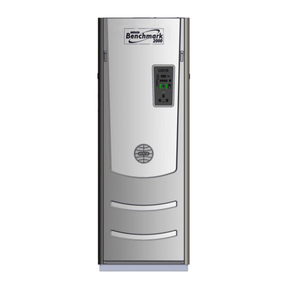
Benchmark 1500 - 2000 Boilers
Installation, Operation & Maintenance Manual (IOMM)
USER MANUAL
Natural Gas Modulating
Installation, Operation and Maintenance
& Condensing Hot Water
Boiler Models:
BENCHMARK
• BMK 1500
1500 / 2000
• BMK 2000
Gas-Fired Boilers
Applicable to Serial Numbers:
G-13-1690 and Above
Latest Update: 11/21/2013
AERCO International, Inc. • 100 Oritani Dr. • Blauvelt, NY 10913
OMM-0097_0C
Page 1 of 184
Ph.: 800-526-0288
GF-142
Advertisement
Table of Contents


Need help?
Do you have a question about the BMK 1500 and is the answer not in the manual?
Questions and answers