
Related Manuals for Benchmark UNICA HE Series


Summary of Contents for Benchmark UNICA HE Series
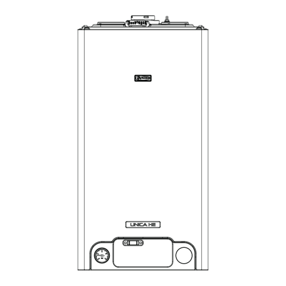
- Page 1 Installation & Servicing Instructions 0694 0694BR1207 THESE INSTRUCTIONS TO BE RETAINED BY USER G.C. NUMBER UNICA 28HE N° 470 94 83 UNICA 32HE N° 470 94 85 UNICA 36HE N° 470 94 87...
-
Page 2: Table Of Contents
10.5 Gas supply installation Fitting the flue 10.6 Adjusting the gas valve Connecting the gas & water 10.7 Appliance fan speed Electrical connections Benchmark Commissioning Page Gas supply installation The heating system Initial filling of the system Initial flushing of the system... - Page 3 INTRODUCTION The Unica HE comprises a range of high-efficiency Unica HE can also be used with the Vokera twin flue combination boilers with outputs to DHW of 28kW, 32kW, system. and 36kW respectively. These appliances – by design The Unica HE is approved for use with C13 & C33 type flue –...
- Page 4 HEATING 2-digit LED RED LED TEMPERATURE GREEN LED TEMPERATURE display SELECTOR SELECTOR HYDROMETRE MODE SELECTOR SWITCH Fig. 1A Hot water only Select this position if you want the boiler to supply hot water only (no heating) Boiler at OFF/standby Select this position when you want the boiler to be switched off or short periods (days) or if the boiler requires to be reset (refer to users handbook) Heating &...
-
Page 5: Design Principles & Operating Sequence
SECTION 1 DESIGN PRINCIPLES AND OPERATING SEQUENCE PRINCIPLE COMPONENTS electronic circuitry increases the gas rate to • A fully integrated electronic control board maximum or will modulate output to stabilise the featuring electronic temperature control, anti- temperature. cycle control, pump over-run, self-diagnostic fault indicator, full air/gas modulation. -
Page 6: Technical Data Page
SECTION 2 TECHNICAL DATA 2.1 Central Heating Unica 28HE Unica 32HE Unica36HE Heat input (kW) Maximum heat output (kW) 60/80°C 19.6 24.45 29.31 Minimum heat output (kW) 60/80°C 6.84 Maximum heat output (kW) 30/50°C 21.00 26.30 31.83 Minimum heat output (kW) 30/50°C 6.40 7.47 7.41... -
Page 7: Pump Duty
2.12 PUMP DUTY Fig. 3 shows the flow-rate available – after allowing for pressure loss through the appliance – for system requirements. When using this graph, apply only the pressure loss of the system. The graph is based on a 20 C temperature differential. -
Page 8: General Requirements (Uk)
SECTION 3 GENERAL REQUIREMENTS (UK) This appliance must be installed by a competent the appliance gas inlet connection must not be person in accordance with the Gas Safety used. The installation must be tested for (Installation & Use) Regulations. soundness in accordance with BS6891. RELATED DOCUMENTS If the gas supply serves more than one appliance, The installation of this boiler must be in accordance... -
Page 9: Electrical Supply
3.6.2 AUTOMATIC BY-PASS Make-up vessel The appliance has a built-in automatic by-pass, or tank consequently there is no requirement for an external by-pass, however the design of the system should Automatic be such that it prevents boiler ‘cycling’. air-vent 3.6.3 DRAIN COCKS These must be located in accessible positions to Non-return... -
Page 10: Related Documents
SECTION 3A GENERAL REQUIREMENTS (EIRE) such pluming must be considered. This appliance must be installed by a competent person If installed less than 2m above a pavement or in accordance with and defined by, the Standard platform to which people have access (including Specification (Domestic Gas Installations) balconies or flat roofs) the terminal must be Declaration (I.S. -
Page 11: Electrical Supply
3A.6.7 LOW PRESSURE SEALED SYSTEM An alternative method of filling the system would be from an independent make-up vessel or tank mounted in a position at least 1 metre above the highest point in the system and at least 5 metres above the boiler (see fig. -
Page 12: Installation
SECTION 4 INSTALLATION DELIVERY horizontal plane (see 2.9). A reduction must also Due to the weight of the appliance it may be be made to the maximum length (see table below) necessary for two people to lift and attach the when additional bends are used. - Page 13 FITTING THE HORIZONTAL FLUE KIT Carefully measure the distance from the centre of the appliance flue outlet to the edge of the finished outside wall (dimension X). Add 65mm to dimension X to give you Dimension Y (see fig 9A). Measure dimension Y from the terminal end of the concentric flue pipe and cut off the excess ensuring any burrs are removed.
- Page 14 4.5.3 TWIN FLUE SYSTEM The Vokera twin flue system enables greater flue distances to be achieved (see 4.4.2) than that of a concentric flue system. It can be used for “X” “X” horizontal or vertical applications, however the 28/32/36 HE = 218 mm 12/15/20HE = 202mm twin flue system must be converted to the dedicated 25/30/35HE = 218mm...
- Page 15 connects to the exhaust connection on the screws – install the air inlet plate (B). • Using the hole in the exhaust connection manifold concentric to twin converter. as a guide, drill a 3mm hole in the appliance flue If necessary cut the plain ends (male) of the twin spigot and secure the exhaust manifold flue pipes to allow connection to the concentric to connection to the flue spigot using the screw...
-
Page 16: Connecting The Gas & Water
The appliance is supplied with a fixing jig that includes service valves (fig. 14). The service valves are of the compression type. The accessories pack contains sealing washers etc, for use with the service valves. When connecting pipe work to the valves, tighten the compression end first then insert the sealing washers before tightening the valve to the appliance. -
Page 17: Electrical Connections
4.6.5 SAFETY VALVE (fig. 16) Connect the safety valve connection pipe to the safety valve outlet. Connect a discharge pipe to the other end of the safety valve connection pipe and tighten. The discharge pipe must have a continuous fall away from the appliance to outside and allow any water to drain away thereby eliminating the possibility of freezing. -
Page 18: Commissioning
SECTION 5 COMMISSIONING GAS SUPPLY INSTALLATION INITIAL FLUSHING OF THE SYSTEM Inspect the entire installation including the gas The whole of the heating system must be flushed meter, test for soundness and purge. Refer to BS both cold and hot as detailed in 5.8. Open all 6891 (I.S. -
Page 19: Final Flushing Of The Heating System
Complete details of the boiler, controls, installation BAR and a maximum of 1.5 BAR. The actual and commissioning in the Benchmark checklist reading should ideally be 1 BAR plus the equivalent at the back of this book. It is important that the height in metres (0.1 BAR = 1 metre) to the highest... -
Page 20: General
SECTION 6 SERVICING INSTRUCTIONS GENERAL content from the appliance via the drain valve. Ensure some water absorbent cloths are available To ensure the continued safe and efficient to catch any residual water that may drip from operation of the appliance, it is recommended that the appliance or removed component. -
Page 21: Safety Valve
SAFETY VALVE (fig. 23) 6.11 PRINTED CIRCUIT BOARD (fig. 25) Carry out component removal procedure as Carry out component removal procedure as described in 6.4. Disconnect the outlet pipe (A) described in 6.4. Pull the control fascia forward from the safety valve, remove safety valve locking and lower it. -
Page 22: Electrodes And Condense Sensor
6.13 ELECTRODES & CONDENSE SENSOR (fig. 27) (D). Disconnect the electrode leads and ancillary wiring from their respective connectors. Remove Carry out component removal procedure as the retaining screws (A, fig. 29) for sensing described in 6.4. Unclip and remove the air chamber electrode and remove. -
Page 23: Automatic By-Pass
Fig. 31: To remove the fan burner assembly (A) locate and remove the 3 external nuts (B). Replace in the reverse order. Ensure all seals are in good condition, taking care to ensure they are replaced correctly. 6.17 AUTOMATIC BY-PASS & DHW NON-RETURN VALVE (fig. - Page 24 6.20.1 DHW FLOW RESTRICTOR (Fig. 35A) 6.20.4 DHW THERMISTOR (Fig. 35B) Carry out the component removal procedure as Carry out component removal procedure as described in 6.4. described in 6.4. Disconnect the cold water inlet pipe at the DHW Locate and remove the thermistor locking pin (H). flow switch (A).
-
Page 25: Checks, Adjustments And Fault Finding
SECTION 7 CHECKS, ADJUSTMENTS AND FAULT FINDING have been designed to further increase fuel CHECKING APPLIANCE OPERATION economy by ensuring the boiler remains in the When carrying out any repairs or servicing to the modulation phase during any heating requests. appliance, the relevant commissioning procedure This reduces the amount of ON/OFF periods must be undertaken to ensure the continued safe... -
Page 26: Appliance Fan Speed
temperature increases, the temperature sensors 7.3.3 ABSOLUTE MIN FAN SPEED – located on the flow pipe of the boiler – reduce Locate the MIN trimmer (fig. 36) and gently adjust the fan speed via the electronic circuitr y. clockwise or counter clockwise to achieve the Depending on the load, either the water correct fan speed (see table 7.3.6). -
Page 27: Combustion Analysis Test
7.7.1 INSTALLATION FAULTS Maximum Symptom Possible cause screw Compensation No display/ignition Check wiring/check electrical pipe connection supply No hot water Check pipe-work No heating Check external controls Minimum screw Fault code Possible cause Check gas supply, check flue fig. 37 system, check polarity 7.4.2 GAS VALVE MINIMUM SETTING... -
Page 28: Fault Finding
These series of checks must be carried out before 7.12 COMPONENT VALUES & CHARACTERISTICS attempting any faultfinding procedures on the COMP ONENT VALUE appliance. On completion of any task that required 230Vac the disconnection and re-connection of any Pump 230Vac electrical wiring or component, these checks must Valve actuator (Combi only) 230Vac... -
Page 29: Wiring Diagrams
SECTION 8 WIRING DIAGRAMS EXTERNAL WIRING Isolate the appliance from the electrical supply The appliance comes with a factory fitted (TA) and remove the clock blanking disc from the clock link to allow basic operation of the boiler via the aperture on the boiler. - Page 30 FUNCTIONAL DIAGRAM Fig. 38 NOTE: L-N-E connection is advisable F Hv Fan power supply 230 V M3-M5 Terminal strip for supply in / clock / room thermostat F Lv Fan signal control M3a-M4 Terminal strip for esternal sensor / condense pump / low Pump temperature thermostat...
-
Page 31: Exploded Diagrams
SECTION 9 EXPLODED DIAGRAMS Table 1 28 HE 30 HE/35 HE POS. DESCRIPTION 28 HE 32 HE 36 HE Frame assembly 01005403 01005446 01005406 Pressure gauge 2564 2564 2564 Cover assembly 10028554 10028554 10028554 Printed Circuit Board 10028558 10028558 10028558 Led light guide 10028557 10028557... -
Page 32: Table 2
Table 2 28 HE 32 HE/36 HE POS. DESCRIPTION 28 HE 32 HE 36 HE Condensing exchanger assembly 8037 1957 10024627 Fitting/union 10024640 10024640 10024640 Pressure switch 10028141 10028141 10028141 Non return valve 10025056 10025056 10025056 By-pass casing 10024641 10024641 10024641 Heating by-pass valve 2047... -
Page 33: Table 3
Table 3 28 HE 32 HE/36 HE POS. DESCRIPTION 28 HE 32 HE 36 HE Expansion vessel 2204 2573 2573 Pipe 10025188 10025188 10025188 Pump 10027571 10027571 10027571 Wiring harness (pump) 10028633 10028633 10028633 Pipe 10028428 10026264 10026264 Pipe 10027317 10027317 10027317 Pipe... -
Page 34: Table 4
Table 4 28 HE 30 HE/35 HE POS. DESCRIPTION 28 HE 32 HE 36HE Roomsealed chamber 10028341 10028447 10028447 Side 10026231 10026231 10026231 10028456 10028456 10028456 Burner 10028537 10028642 10028537 Spark/ignition electrode 10027864 10027864 10027864 Condense electrode 10026316 10026316 10026316 Gas pipe 10028620 10026318... -
Page 35: Table 5
28 HE Table 5 30 HE/35 HE POS. DESCRIPTION 28 HE 32 HE 36 HE Condensing exchanger assembly 01005443 01005366 01005369 Conveyor 10028536 10028623 10028623 Flue drain connection 10028421 10028421 10028421 Washer 10026323 10026323 10026323 Washer 10026366 10026366 10026366 Washer 10026345 10026345 10026345... -
Page 36: Related Documents
SECTION 10 LPG INSTRUCTIONS 10.1 RELATED DOCUMENTS BS 5440 PARTS 1 & 2 FLUES & VENTILATION REQUIREMENTS BS 5449 PART 1 FORCED CIRCULATION OF HOT WATER SYSTEMS BS 5482 PART 1 DOMESTIC BUTANE & PROPANE GAS BURNERS IN PERMAMENT DWELLINGS BS 5546 INSTALLATION OF GAS HOT WATER SUPPLIES FOR DOMESTIC PURPOSES... -
Page 37: Appliance Fan Speed
IMPORTANT A GAS SOUNDNESS CHECK MUST BE CARRIED OUT IF ANY GAS CARRYING COMPONENTS HAVE BEEN REMOVED, REPLACED, OR DISTURBED . FAN SPEED (rpm) TABLE - LPG MODEL 28HE 6100 1700 4300 3700 32HE 5900 1500 4500 3700 36HE 6300 1400 5200 3700... -
Page 38: Benchmark
BENCHMARK No. GAS BOILER COMMISSIONING CHECKLIST C O L L E C T I V E M A R K BOILER SERIAL No. NOTIFICATION No. CONTROLS To comply with the Building Regulations, each section must have a tick in one or other of the boxes TIME &... - Page 39 SERVICE INTERVAL RECORD It is recommended that your heating system is serviced regularly and that you complete the appropriate Service Interval Record Below. Service Provider. Before completing the appropriate Service Interval Record below, please ensure you have carried out the service as described in the boiler manufacturer’s instructions.
- Page 40 Vokèra Ireland West Court, Callan, Co Kilkenny Tel: 05677 55057 Fax: 05677 55060 Vokèra Ltd. reserve the right to change the specifications without prior notice. Consumers’ statutory rights are not affected. A Riello Group Company COLLECTIVE MARK “Vokèra” supports Benchmark...
Need help?
Do you have a question about the UNICA HE Series and is the answer not in the manual?
Questions and answers