Fluke 5080A Operator's Manual
Hide thumbs
Also See for 5080A:
- Service manual (116 pages) ,
- Getting started manual (38 pages) ,
- Manual (56 pages)

Related Manuals for Fluke 5080A


Summary of Contents for Fluke 5080A
- Page 1 5080A Calibrator Operators Manual July 2012 © 2012 Fluke Corporation. All rights reserved. Specifications are subject to change without notice. All product names are trademarks of their respective companies.
- Page 2 Fluke authorized resellers shall extend this warranty on new and unused products to end-user customers only but have no authority to extend a greater or different warranty on behalf of Fluke. Warranty support is available only if product is purchased through a Fluke authorized sales outlet or Buyer has paid the applicable international price.
- Page 3 OPERATOR SAFETY SUMMARY WARNING HIGH VOLTAGE is used in the operation of this equipment LETHAL VOLTAGE may be present on the terminals, observe all safety precautions! To avoid electrical shock hazard, the operator should not electrically contact the output HI or sense HI terminals or circuits connected to these terminals. During operation, lethal voltages of up to 1020 V ac or dc may be present on these terminals.
-
Page 5: Table Of Contents
Operation Overview ................... 1-5 Where to Go from Here ..................1-5 Instruction Manuals ................... 1-6 5080A Operators Manual ................1-6 5080A Getting Started Manual ..............1-6 How to Contact Fluke ..................1-6 General Specifications ..................1-7 Detailed Specifications ..................1-8 DC Voltage .................... - Page 6 5080A Operators Manual Features ....................3-1 Introduction ......................3-3 Front-Panel Features ..................3-3 Rear-Panel Features ................... 3-3 Softkey Menu Trees ................... 3-3 Front-Panel Operations............... 4-1 Introduction ......................4-3 Turning on the Calibrator................... 4-3 Warming up the Calibrator ................4-4 Using the Softkeys ..................... 4-4 Using the Setup Menu ..................
- Page 7 Extra Space or Tab Characters ..............5-15 Terminators ....................5-15 Incoming Character Processing ..............5-15 Response Message Syntax ................ 5-15 Checking 5080A Status ..................5-17 Serial Poll Status Byte (STB) ................ 5-17 Master Summary Status ................5-19 Service Request Enable Register (SRE) ............ 5-19 Programming the STB and SRE..............
- Page 8 5080A Operators Manual How to Replace the Current Fuses ..............7-5 How to Clean the Air Filter ................7-7 General Cleaning ....................7-8 Performance Tests ....................7-9 Appendices A Glossary ....................... A-1 B RS-232 Cabling and Connector ..............B-1 C Error Messages .................... C-1...
- Page 9 Table Title Page 1-1. Symbols ........................1-4 2-1. Standard Equipment ....................2-3 2-2. Line Power Cord Types Available from Fluke ............2-6 2-3. Accessories and Options ..................2-8 3-1. Front-Panel Features ....................3-4 3-2. Rear-Panel Features ....................3-9 3-3. Factory Defaults for SETUP Menus Power-Up Defaults ........3-20 4-1.
- Page 10 5080A Operators Manual 7-12. Verification Tests for Frequency ................7-15...
- Page 11 List of Figures Figure Title Page 2-1. Fuse Access and Line Voltage Selection ............... 2-5 2-2. Line Power Cord Types Available from Fluke ............2-6 3-1. Front-Panel View ....................3-4 3-2. Rear-Panel View ....................3-9 3-3. SETUP Softkey Menu Tree ..................3-11 4-1.
- Page 12 5080A Operators Manual viii...
-
Page 13: Title
Operation Overview ..................... 1-5 Where to Go from Here ..................1-5 Instruction Manuals ..................... 1-6 5080A Operators Manual ................1-6 5080A Getting Started Manual ................ 1-6 How to Contact Fluke ..................1-6 General Specifications ..................1-7 Detailed Specifications ..................1-8 DC Voltage ...................... - Page 14 5080A Operators Manual...
-
Page 15: Introduction
Introduction Introduction Warning If the 5080A Calibrator is operated in any way not specified by this manual or other documentation provided by Fluke, the protection provided by the Calibrator may be impaired. The 5080A Calibrator is a fully programmable precision source of the following: •... -
Page 16: Symbols
Go to CAT I connected to mains. Maximum Fluke’s website for recycling transient Overvoltage is as specified by information. terminal markings. This manual contains information, warnings, and cautions that must be followed to ensure safe operation and to maintain the Calibrator in a safe condition. -
Page 17: Operation Overview
Operation Overview The 5080A Calibrator may be operated at the front panel in the local mode, or remotely using RS-232 or Ethernet ports. For remote operations, several software options are available to integrate 5080A operation into a wide variety of calibration requirements. -
Page 18: Instruction Manuals
5080A Service Manual (PN 3790039) The Operators and Getting Started manuals listed above are shipped with the Calibrator. For ordering instructions, refer to the Fluke Catalog, or ask a Fluke sales representative (see “Service Information” in Chapter 2). To view, print, or download the latest manual supplement, visit http://us.fluke.com/usen/support/manuals. -
Page 19: General Specifications
All specifications are valid after a warm-up period of 30 minutes, or twice the time since last warmed up, to a maximum of 30 minutes. For example, if the 5080A has been turned off for 5 minutes, the warm-up period is 10 minutes. -
Page 20: Detailed Specifications
60 minute period where T is the temperature in °C (room temperature is about 23 °C) and I is the output current in Amps. For example, 17 A at 23 °C could be provided for 60-17-23 = 20 minutes each hour. When the 5080A is outputting currents between 5 and 11 amps for long periods, the internal self-heating reduces the duty cycle. -
Page 21: Resistance
Introduction and Specifications Detailed Specifications Noise Range Bandwidth 0.1 Hz to 10 Hz, p-p Bandwidth 10 Hz to 10 kHz, rms 20 nA 60 nA 0 to 329.99 μA 0 to 3.2999 mA 200 nA 600 nA 0 to 32.999 mA 2 μA 6 μA 0 to 329.99 mA... -
Page 22: Ac Voltage (Sine Wave)
5080A Operators Manual AC Voltage (Sine Wave) Specification, tcal ±5 °C ±(% of Max. Distortion & Noise 10 Hz to 100 kHz output + μV) Max. Range Frequency Resolution Bandwidth Burden 90 days 1 year ±(% of output + floor) 1.00 to... -
Page 23: Ac Current (Sine Wave)
60 minute period where T is the temperature in °C (room temperature is about 23 °C) and I is the output current in amps. For example, 17 A at 23 °C could be provided for 60-17-23 = 20 minutes each hour. When the 5080A is outputting currents between 5 and 11 amps for long periods, the internal self-heating reduces the duty cycle. -
Page 24: Dc Power Summary
5080A Operators Manual DC Power Summary Currents 0.33 to 3.2999 mA 3.3 to 329.99 mA 0.33 to 2.9999 A 3 to 20.5 A Time Voltage Specification, tcal ±5 °C, ±(% of watts output) 90 days 33 mV to 1020 V 0.14... -
Page 25: Phase
Introduction and Specifications Detailed Specifications Phase [1][2] Specification, 1 year, tcal ±5 °C, ±(ΔΦ) 45 TO 65 Hz 65 to 500 Hz 500 Hz to 1 kHz 0.25 ° 1.5 ° 5.0 ° See Power and Dual Output Limit specifications for applicable outputs. Phase settling times are typically <18 seconds additional. -
Page 26: Frequency
5080A Operators Manual Current Specification Specification for 1 A is 0.10 % + 1200 μA, totaling: 1 A x 0.001 = 1000 μA added to 1200 μA = 2.2 mA. Expressed in percent: 2.2 mA/1 A x 100 = 0.22 % (see “AC Current Specifications”). -
Page 27: Operation Preparation
Chapter 2 Operation Preparation Title Page Introduction ......................2-3 Unpacking and Inspection..................2-3 Replacing the Fuse ....................2-3 Selecting Line Voltage ..................2-4 Connecting to Line Power ................... 2-4 Selecting Line Frequency ..................2-4 Service Information ..................... 2-6 Cooling Considerations ..................2-7 Accessories and Options .................. - Page 28 5080A Operators Manual...
-
Page 29: Introduction
Report any shortage to the place of purchase or to the nearest Fluke Service Center (see “Service Information” in this section). A performance test is provided in Chapter 7, “Maintenance.”... -
Page 30: Selecting Line Voltage
You can operate the 5080A Calibrator from one of four line voltage settings: 100 V, 120 V, 220 V, and 240 V (47 Hz to 63 Hz). To check the line voltage setting, note the voltage setting visible through the window in the power line fuse compartment cover (Figure 2-1). - Page 31 Operation Preparation Selecting Line Frequency LINE VOLTAGE INDICATOR CHANGING LINE FUSE CHANGING LINE VOLTAGE nn007f.eps Figure 2-1. Fuse Access and Line Voltage Selection...
-
Page 32: Service Information
Figure 2-2. Line Power Cord Types Available from Fluke Service Information Each Model 5080A Calibrator is warranted to the original purchaser for a period of 1 year beginning on the date received. The warranty is located at the front of this manual. -
Page 33: Cooling Considerations
Operation Preparation Cooling Considerations Cooling Considerations Warning To avoid risk of injury, never operate or power the Calibrator without the fan filter in place. Caution Damage caused by overheating may occur if the area around the air intake or exhaust is restricted, the intake air is too warm, or the air filter becomes clogged. -
Page 34: Accessories And Options
Manual Calibration Software. MET/BASE and MET/TRACK required. Manual MET/CAL Options can be ordered factory installed with a new calibrator (5080A/MEG, 5080A/SC, and 5080A/SC/MEG), or added later at a Fluke service center for an additional installation and calibration charge. Rack Mount Considerations Rack mount the Calibrator using a support shelf or drawer. -
Page 35: Features
Chapter 3 Features Title Page Introduction ......................3-3 Front-Panel Features .................... 3-3 Rear-Panel Features ..................... 3-3 Softkey Menu Trees ..................... 3-3... - Page 36 5080A Operators Manual...
-
Page 37: Introduction
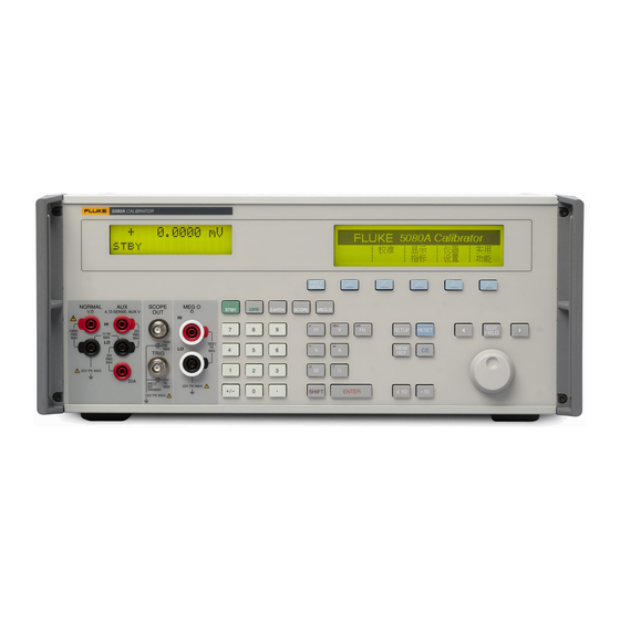
Introduction Introduction This chapter is a reference for the functions and locations of the 5080A Calibrator's front- and rear-panel features. Please read this information before operating the Calibrator. Front-panel operating instructions for the Calibrator are provided in Chapter 4, “Front- Panel Operation”;... -
Page 38: Front-Panel Features
Calibrator status. Output values (or potential output values if in standby) are displayed using up to six digits plus a polarity sign. Output frequencies (or potential output frequencies if the 5080A is in standby) are displayed using four digits. Calibrator status is indicated by displaying the following abbreviations: Displayed when an output is active at the front-panel terminals. - Page 39 An overload condition is detected. The OPR (Operate) key places the 5080A in operate mode. Operate mode is indicated by “OPR” in the lower left corner of the Output Display and the lit indicator on the OPR key. ...
- Page 40 The SETUP (Setup Menu) key puts the 5080A in the setup mode, displaying the setup menu in the Control Display. Setup options can be selected using the softkeys under the Control Display.
- Page 41 ENTER with no value restores the output to the value of the reference. Output Units Keys The output units keys determine the function of the 5080A. Some keys have a second unit if the SHIFT key is pressed just before the units key. The output units are as follows: Volts or Decibels relative to 1 mW into 600 ohms (impedance changeable).
- Page 42 5080A Operators Manual gew325f.eps Figure 3-1. Front-Panel View (cont.) Table 3-1. Front-Panel Features (cont.) The (Polarity) key changes the polarity of the output for dc voltage or dc current functions. Press the key then to toggle the output polarity.
-
Page 43: Rear-Panel Features
The Fan Filter covers the air intake to keep dust and debris out of the chassis air baffles. The 5080A fan provides a constant cooling air flow throughout the chassis. Instructions for fan filter maintenance are in Chapter 7, Maintenance. - Page 44 AUX EARTH GROUND terminal for a protective grounding wire. The AUX EARTH GROUNDterminal is internally grounded to the chassis. If the 5080A is the location of the ground reference point in a system, this binding post can be used for connecting other instruments to earth ground.
- Page 45 Features Softkey Menu Trees SETUP Front Panel Key AK AL gew013f.eps Figure 3-3. SETUP Softkey Menu Tree 3-11...
- Page 46 5080A Operators Manual to X to G to B SHOW SPECS is an online summary of the programmed output specifications. to AG to F to C If self test does not pass, error codes are displayed. (See chapter 7, "Maintenance")
- Page 47 Features Softkey Menu Trees Actual revision numbers may be different for each of the above. Format NV (non-volatile) Memory should be used with caution. Changes are non-reversible. The softkeys function only when the rear-panel CALIBRATION switch is set to ENABLE, except for the softkey SETUP, which is not dependent on the CALIBRATION switch position.
- Page 48 5080A Operators Manual to I1 to L STALL refers to the method of controlling data flow: software control (xon/off), hardware control (rts/cts) or none. to M REMOTE I/F (Interface) has selections term (terminal) and comp (computer) (factory default). EOL (End of Line character) is either Carriage Return/Line Feed (CRLF), CR (Carriage Return) or LF (Line Feed).
- Page 49 Features Softkey Menu Trees to N to K EOF (End of File) indicates the action taken at the end of a file by entering one or two ASCII characters. EOF (End of File) ASCII characters are entered with a range of 000 to 255 (first character) and 000 to 255 (second character).
- Page 50 5080A Operators Manual levels 0,1,2,3,4,5,6,7 levels 0,1,2,3,4,5,6,7 There are eight levels of brightness, 0 to 7, for the Output Display and Control Display. Each may have its own level of contrast. The factory defaults are 1 and 2. to T...
- Page 51 AC to AA Select the desired CAL (Calibration) feature: CAL to calibrate the 5080A (see the Service Manual); CAL DATES to review when the 5080A Calibrator was last calibrated; REPORT SETUP to configure calibration reports; PRINT REPORTS to print calibration data.
- Page 52 5080A CAL opens the calibration menu. Refer to the Service Manual for instructions. ZERO zeros the 5080A Calibrator. ERR ACT (Error Action) set backup, abort, or cont (continue). to AF GO ON and ABORT softkeys are used in the 5080A Calibrator calibration procedure. See the Service Manual for more information.
- Page 53 Features Softkey Menu Trees to AH to AJ to AK to AL (Only if option installed) to AF gew022.eps Figure 3-4. SETUP Softkey Menu Displays (cont.) 3-19...
-
Page 54: Factory Defaults For Setup Menus Power-Up Defaults
5080A Operators Manual Table 3-3. Factory Defaults for SETUP Menus Power-Up Defaults Parameter Setting Setup from Figure 3-4 User report string (*PUD string) Cleared Error units >0.1 % Host interface RS-232 Host serial interface comp, 8 bits, 1 stop bit, xon/xoff,... -
Page 55: Front-Panel Operations
Chapter 4 Front-Panel Operations Title Page Introduction ......................4-3 Turning on the Calibrator..................4-3 Warming up the Calibrator .................. 4-3 Using the Softkeys ....................4-4 Using the Setup Menu ..................4-4 Using the Instrument Setup Menu ..............4-5 Utility Functions Menu ..................4-5 Using the Format NV Memory Menu ............. - Page 56 5080A Operators Manual...
-
Page 57: Introduction
For a discussion of the softkey selection shown above (auto/locked), see “Auto Range Versus Locked Range” later in this chapter. Warming up the Calibrator When you turn on the 5080A, allow a warm-up period of at least 30 minutes for the... -
Page 58: Using The Softkeys
5080A Calibrator to 0 V dc in the standby mode. Use the key as your main navigating tool for moving around the menu levels. -
Page 59: Using The Instrument Setup Menu
Front-Panel Operations Using the Setup Menu • UTILITY FUNCTNS (Utility Functions) Allows you to initiate self-tests, format the nonvolatile memory (restore factory default settings), and review the instrument configuration software versions and user report string. These features are explained under “Utilities Function Menu” later in this chapter. Using the Instrument Setup Menu The softkeys in the instrument setup menu (accessed by pressing INSTMT SETUP softkey in the Setup Menu) are shown below. -
Page 60: Using The Format Nv Memory Menu
At any time during front-panel operation (not remote operation), you can return the 5080A Calibrator to the power-up state by pressing , except after an error message, which is cleared by pressing a blue softkey. Pressing the key does the following: •... -
Page 61: Using The Operate And Standby Modes
4. Press the CAL softkey. The calibration activity menu opens (below). SCOPE CAL appears as an option if it is installed. gew070f.eps 5. Press the ZERO softkey to totally zero the 5080A. After the zeroing routine is complete (several minutes), press to reset the calibrator. Using the Operate and Standby Modes When the OPERATE annunciator is lit and OPR is displayed, the output value and function shown on the Output Display is active at the selected terminals. -
Page 62: Connecting The Calibrator To A Uut
(thermal EMFs), use connectors and conductors made of copper or materials that generate small thermal EMFs when joined to copper. Avoid using nickel-plated connectors. Optimum results can be obtained by using Fluke Model 5440A-7002 Low Thermal EMF Test Leads, which are constructed of well-insulated copper wire and tellurium copper connectors. -
Page 63: When To Use Earth
UUT is isolated from earth ground. There must, however, be a safety ground for the 5080A. See “Connecting to Line Power” in Chapter 2. When enabled by the sourced output, a softkey LOs appears, which allows you to tie or open an internal connection between the NORMAL LO terminal and AUX LO terminal. -
Page 64: Cable Connection Instructions
Cable Connection Instructions Table 4-1 indicates a figure reference for each type of connection between a UUT and the 5080A Calibrator, referencing Figures 4-1 through 4-5. To connect the calibrator to a UUT, proceed as follows: 1. If the calibrator is turned on, press to remove the output from the calibrator terminals. - Page 65 Front-Panel Operations Connecting the Calibrator to a UUT TRUE RMS MULTIMETER MIN MAX RANGE HOLD mA A 5080A gew041f.eps Figure 4-2. UUT Connection: Resistance (2-Wire Compensation) TRUE RMS MULTIMETER MIN MAX RANGE HOLD PEAK MIN MAX mA A 5080A gew042f.eps Figure 4-3.
-
Page 66: Auto Range Versus Locked Range
5080A Operators Manual TRUE RMS MULTIMETER MIN MAX RANGE HOLD PEAK MIN MAX mA A gew046f.eps Figure 4-4. UUT Connection: DC Voltage/AC Voltage TRUE RMS MULTIMETER MIN MAX RANGE HOLD PEAK MIN MAX mA A gew047f.eps Figure 4-5. UUT Connection: DC Current/AC Current Auto Range Versus Locked Range A softkey is provided to toggle between the ranging method auto or locked. -
Page 67: Setting The Output
• resistance Setting DC Voltage Output Complete the following procedure to set a dc voltage output at the 5080A front-panel NORMAL terminals. If you make an entry error, press to clear the display, then reenter the value. Caution... -
Page 68: Setting Ac Voltage Output
You may select an ac voltage output in volts or as a power output in dBm, where dBm is 10 log(Pout/.001) , where Pout is expressed in watts. The output range is 1 mV to 1020 V. When selecting dBm outputs, the 5080A calculates dBm at a selected impedance 4-14... - Page 69 Based on this, the formula is: 20 log(V) - 10 log(Impedance * .001) = dBm. Complete the following procedure to set an ac voltage output at the 5080A front-panel NORMAL terminals. If you make an entry error, press to clear the display, then reenter the value.
-
Page 70: Setting Dc Current Output
5080A Operators Manual Control Display using the rightmost softkey. 7. The Control Display now shows the amplitude of your entry. For example, 2.4494 V (below). nn073f.eps 8. Press the numeric keys and decimal point key to enter the desired frequency output (maximum five numeric keys). -
Page 71: Setting Ac Current Output
If you make an entry error, press to clear the display, then reenter the value. 1. Press to clear any output from the 5080A. 2. Connect the UUT as described earlier in this chapter under “Connecting the Calibrator to a UUT.”... -
Page 72: Setting Dc Power Output
Caution To avoid damage to the UUT, verify the applied voltage to the UUT does not exceed the rating of the UUT insulation and the interconnecting wiring. 1. Press to clear any output from the 5080A. 4-18... - Page 73 Front-Panel Operations Setting the Output 2. Connect the UUT as described earlier in this chapter under “Connecting the Calibrator to a UUT” by adapting the voltage and current connections. 3. Set the UUT to measure dc power on the desired range. 4.
-
Page 74: Setting Ac Power Output
“LO”s ties or opens a connection between front-panel NORMAL LO and AUX LO terminals. The front-panel NORMAL LO and AUX LO terminals must be tied together either at the UUT or at the 5080A. The default is tied. Setting AC Power Output... - Page 75 Front-Panel Operations Setting the Output nn084f.eps 8. Press the numeric keys and decimal point key to enter the desired current output (maximum five numeric keys). For example, 234.56. 9. Press a multiplier key, if necessary. For example, press . 10. Press . 11.
-
Page 76: Setting A Dual Dc Voltage Output
UUT does not exceed the rating of the UUT insulation and the interconnecting wiring. 1. Press to clear any output from the 5080A. 2. Connect the UUT as described earlier in this chapter under “Connecting the Calibrator to a UUT.”... - Page 77 “LO”s (Low Potential Output Terminals) The front-panel NORMAL LO and AUX LO terminals must be tied together either at the UUT or at the 5080A. When the front-panel NORMAL LO and AUX LO terminals are tied at the UUT, select “open”...
-
Page 78: Setting A Dual Ac Voltage Output
UUT does not exceed the rating of the UUT insulation and the interconnecting wiring. 1. Press to clear any output from the 5080A. 2. Connect the UUT as described earlier in this chapter under “Connecting the Calibrator to a UUT.”... - Page 79 Front-Panel Operations Setting the Output (maximum five numeric keys). Then press the key. For example, 983.2 Hz. 13. The Control Display now shows your voltage and frequency entries. For example, 123.45 mV and 234.56 mV at 983.2 Hz (below). gew361.eps 14.
- Page 80 • “LO”s (Low Potential Output Terminals) The front-panel NORMAL LO and AUX LO terminals must be tied together either at the UUT or at the 5080A. When the front-panel NORMAL LO and AUX LO terminals are tied at the UUT, select “open”...
-
Page 81: Setting Resistance Output
Front-Panel Operations Setting the Output terminals are not tied at the UUT, select “tied” with the “LO”s softkey. The default is tied. • auxφNOR (Phase Difference) Selects the phase difference between the NORMAL and AUX outputs. See “Adjusting the Phase” later in this chapter. Setting Resistance Output In the resistance function, the calibrator supplies your choice of 18 standard resistance values or a short at the output terminals. -
Page 82: Sine Wave Output
5080A Operators Manual gew356.eps 9. After you specify a valid resistance and press , the calibrator clears your entry from the Control Display and shows the characterized (true) resistance value on the Output Display (below is typical). gew365.eps 10. Press to activate the calibrator output. -
Page 83: Adjusting The Phase
Front-Panel Operations Adjusting the Phase Peak RMS (70% Peak) Period nn026f.eps Figure 4-6. Sine Wave Adjusting the Phase When in the dual ac voltage and ac power output modes, you can set the calibrator to source two signals with adjustable phase difference. All phase adjustments shift the AUX waveform in relation to the NORMAL waveform. -
Page 84: Entering A Phase Angle
5080A Operators Manual nn110f.eps Entering a Phase Angle Complete the following procedure to enter a phase shift in degrees. This procedure assumes you have already sourced a dual ac voltage or ac power output. 1. Press the softkey WAVE MENUS, opening the waveform menu. -
Page 85: Entering A Power Factor
Front-Panel Operations Editing and Error Output Settings nn111f.eps 6. Press . The calibrator clears your entry from the “New phase =” line and copies it to the “Phase =” line of the Control Display. 7. Press one or more times to return to previous menus. Entering a Power Factor Complete the following procedure to enter a phase shift as a power factor (PF). -
Page 86: Editing The Output Setting
5080A Operators Manual Table 4-3. Keys That Exit Error Mode Keys Action Returns to the previous reference value. + Establishes a new reference. A new keypad entry + Establishes a new reference. Establishes the present output as a new reference. -
Page 87: Displaying The Uut Error: Resistance Output
Front-Panel Operations Setting Voltage and Current Limits magnitude. For example, if the reference is -10.0000 V and the output display is -10.0003, the error is -30 ppm. Displaying the UUT Error: Resistance Output In the resistance output function, the edit controls produce a display of the UUT error in a similar way, except the output of the calibrator does not change as you turn the knob. - Page 88 5080A Operators Manual nn118f.eps a. Press the “Upper Limit” or the “Lower Limit” softkey, as desired, and enter the new limit. b. Press then one or more times to return to a previous menu. 6. To Limit Current (applies to both dc and ac currents). Press a softkey under CURRENT to open the current limits menu (below).
-
Page 89: Remote Operations
Command Syntax .................... 5-13 Parameter Syntax Rules ................5-13 Extra Space or Tab Characters ..............5-15 Terminators ....................5-15 Incoming Character Processing ..............5-15 Response Message Syntax ................5-15 Checking 5080A Status ..................5-17 Serial Poll Status Byte (STB) ................5-17... - Page 90 5080A Operators Manual Master Summary Status ................5-19 Service Request Enable Register (SRE) ............5-19 Programming the STB and SRE..............5-19 Event Status Register (ESR) ............... 5-19 Event Status Enable (ESE) Register ............5-19 Bit Assignments for the ESR and ESE ............5-20 Programming the ESR and ESE ..............
-
Page 91: Introduction
RS-232 The serial port connects the PC and Calibrator. You can write your own computer programs using the command set, or operate the PC as a terminal and enter individual commands, or you can purchase optional Fluke MET/CAL or 5080/CAL software for RS-232 system operations. Typical RS-232 remote configurations are shown in Figure 5-1. -
Page 92: Setting Up The Rs-232 Host Port For Remote Control
(Figure 5-1). You can enter individual commands from a terminal, write your own programs using, for example, a Windows-based language such as Visual Basic, or run optional Windows-based Fluke software such as 5080/CAL or MET/CAL. The RS-232 cable length for the port should not exceed 15 meters (50 feet), although longer cable lengths are permitted if the load capacitance measured at a connection point (including signal terminator) does not exceed 2500 pF. -
Page 93: Configuring The Ethernet (Lan) Port
Remote Operations Configuring the Ethernet (LAN) Port gew328.eps 5. Press (not ) several times until the message STORE CHANGES/DISCARD CHANGES appears or, if there were no changes, clear the display. If you select STORE CHANGES, the serial and host port setting are saved in the instrument non-volatile memory. -
Page 94: Setting The Ip Address
5080A Operators Manual 3. Push the softkey labeled REMOTE SETUP. 4. Push the softkey labeled LAN SETUP. The LAN parameters are set through the two softkey menus shown in Figure 5-2. gew336.eps Figure 5-2. Menus to Set LAN Parameters Note When addressing some LAN addresses, computers will often interpret 0's in the IP address as OCTAL values. -
Page 95: Setting A Static Internet Address
1. From the LAN menu, push NEXT MENU to show the second LAN menu. 2. Push the softkey labeled DOMAIN NAME. Configuring the Host Name The Host Name is the host portion of the domain name, which is translated into an IP address. The Calibrator’s default host name is “FLUKE-5080A-snxxxx”. -
Page 96: Reading The Mac Address
5080A Operators Manual To change the Host Name: 1. From the LAN menu, push the softkey labeled HOST NAME. 2. Push . 3. Push and to position the cursor under a character in the host name shown in the display. -
Page 97: Establishing An Ethernet Connection
3490, enter the following at a command prompt from any client computer: telnet 129.196.136.131 3490 If you are using DHCP and the host name is FLUKE-5080A-snxxxx and the fully qualified domain name is FLUKE-5080A-snxxxx.na.flukecorp.com and the Socket Port is set to 3490, enter the following at the computer command prompt: telnet FLUKE-5080A-snxxxx.na.flukecorp.com 3490... -
Page 98: Changing Between Remote And Local Operation
LOCAL returns the Calibrator to the local state. Remote with Lockout State When the Calibrator is placed in lockout, via the remote command, the 5080A front- panel controls are totally locked out. In remote with lockout, the Control Display changes gew334f.eps... -
Page 99: Rs-232 Interface Overview
Remote Operations RS-232 Interface Overview Table 5-1. Operating State Transitions From Front Panel Serial Command Local Remote REMOTE Local with Lockout LOCKOUT Remote Local Go to Local Softkey LOCAL Remote with Lockout LOCKOUT Local with Lockout Local LOCAL Remote with Lockout REMOTE Remote with Lockout Local... -
Page 100: Common Commands
5080A Operators Manual Common Commands Common commands are defined by the IEEE 488.2 standard and are common to most bus devices. Common commands always begin with an * character. An example of a common command is: *IDN? This command instructs the Calibrator to return the instrument identification string. -
Page 101: Sequential Commands
For example: OUT 1 V, 1 A, 60 HZ ; *WAI You can also use the status commands *OPC and *OPC? to detect completion of overlapped commands. (See “Checking 5080A Status.”) Sequential Commands Commands that execute immediately are called sequential commands. -
Page 102: Units Accepted In Parameters And Used In Responses
5080A Operators Manual Table 5-2. Units Accepted in Parameters and Used in Responses Units Meaning Frequency in units of hertz Frequency in units of kilohertz Frequency in units of megahertz Volts in units of microvolts Volts in units of millivolts... -
Page 103: Extra Space Or Tab Characters
Remote Operations Using Commands how many data bytes follow. For examples, see the *PUD command descriptions in Chapter 6. Extra Space or Tab Characters In the command descriptions in Chapter 6, parameters are shown separated by spaces. One space after a command is required (unless no parameters are required). All other spaces are optional. -
Page 104: Response Data Types
±E20. Example: POWER? returns: 1.4293E+00 String Any ASCII characters including quotation mark delimiters. Example: SRQSTR “SRQ from 5080A”; SRQSTR? returns: “SRQ from 5080A” Character This type of response is always a keyword. Response Example: OUT 10V, 100HZ; FUNC? Data (CRD) -
Page 105: Checking 5080A Status
Remote Operations Checking 5080A Status Checking 5080A Status The programmer has access to status registers, enable registers, and queues in the Calibrator to indicate various conditions in the instrument as shown in Figure 5-2. Some registers and queues are defined by the IEEE-488.2 standard. The rest are specific to the Calibrator. - Page 106 5080A Operators Manual Instrument Status 8 7 6 5 4 3 2 1 0 Change Enable Registers & & Write using & ISCE0 (1 to 0 transition) & ISCE1 (0 to 1 transition) & ISCE (1 to 0 AND 0 to 1) &...
-
Page 107: Master Summary Status
Set to 1 when one or more enabled ESR bits are 1. Message available. The MAV bit is set to 1 whenever data is available in the 5080A’s output buffer. Error available. An error has occurred and an error is available to be read from the error queue by using the ERR? query. -
Page 108: Bit Assignments For The Esr And Ese
15 errors that have occurred.) Execution error. An error occurred while the 5080A tried to execute the last command. This could be caused, for example, by a parameter being out of range. (The command ERR? fetches the earliest error in the error queue, which contains error codes for the first 15 errors that have occurred.) -
Page 109: Instrument Status Change Enable Registers
TMPCAL Set to 1 when the 5080A is using temporary (non-stored) calibration data. OPER Set to 1 when the 5080A is in operate, 0 when it is in standby. gew333.eps Figure 5-6. Bit Assignments for the ISR, ISCEs, and ISCRs... -
Page 110: Programming The Isr, Iscr, And Isce
5080A Operators Manual Programming the ISR, ISCR, and ISCE To read the contents of the ISR, send the remote command, ISR?. To read the contents of the ISCR0 or 1, send the remote command, ISCR0?, or ISCR1?. To read the contents of the ISCE0 or 1, send the remote command, ISCE0?, or ISCE1?. -
Page 111: Remote Commands
Chapter 6 Remote Commands Title Page Introduction ......................6-3 Command Summary by Function ................ 6-3 Command Details ....................6-7... - Page 112 5080A Operators Manual...
-
Page 113: Introduction
Remote Commands Introduction Introduction This chapter documents the remote commands for the 5080A Calibrator (hereafter referred to as “the Calibrator”). Remote commands duplicate activities that can be initiated from the front panel in local operation. Following the summary table is a complete alphabetical listing of all commands, complete with protocol details. -
Page 114: Error Mode Command Summary
5080A Operators Manual Table 6-2. Error Mode Command Summary Command Description EDIT Sets the edit field. PRI is specified for the output value in single output functions and the primary output value in dual output functions. EDIT? Returns the edit field setting. -
Page 115: Rs-232 Host Port Command Summary
Remote Commands Command Summary by Function Table 6-4. Output Command Summary (cont.) Command Description LCOMP? Returns whether inductive load compensation for ac current output is active. OPER Activates the Calibrator output if it is in standby. OPER? Returns the operate/standby setting. Sets the output of the Calibrator and establishes a new reference point for the error mode. -
Page 116: Setup And Utility Command Summary
5080A Operators Manual Table 6-6. Setup and Utility Command Summary Command Description CLOCK Sets the real-time clock. CLOCK? Queries the real-time clock. DBMZ_D Sets the power-up and reset default impedance used for dBm outputs (ac volts). DBMZ_D? Returns the power-up and reset default impedance used for dBm outputs (ac volts). -
Page 117: Command Details
Remote Commands Command Details Table 6-6. Setup and Utility Command Summary (cont.) Command Description SP_SET? Returns the HOST serial port communication parameters contained in nonvolatile memory. SUBNETMASK Sets the LAN subnet IP mask. SUBNETMASK? Returns the LAN subnet IP mask. UNCERT? Retums specified uncertainties for the present output. -
Page 118: Overlapped And Coupled Commands
5080A Operators Manual Overlapped Commands – Commands that require additional time to execute are called overlapped commands because they can overlap the next command before completing execution. To be sure an overlapped command is not interrupted during execution, use the *OPC, *OPC?, and *WAI commands to detect command completion. See Table 6-8 for all the commands that are classified as overlapped. - Page 119 Remote Commands Command Details Sets the clock time to 1:10:10 PM CLOCK 13,10,10 Query Retrieves clock data: 1998-12- CLOCK? 04,13:03:50. *CLS Description Clears the ESR, ISCR0, ISCR1, the error queue, and the MSS bit in the status byte. This command terminates pending operation complete commands (*OPC or *OPC?).
- Page 120 5080A Operators Manual Z1200 1200 ohms Example Sets the power-up and reset default impedance DBMZ_D Z90 for dBm outputs to 90 ohms. Query Retrieves the power-up and reset defaults DBMZ_D? impedance for dBm outputs. DHCP(?) [{ON|OFF}] Description Enables/disables Dynamic Host Configuration Protocol (DHCP) operation.
- Page 121 Remote Commands Command Details EDIT(?) <value > Description Sets the edit field to the primary, secondary or frequency field. Parameters <value> = PRI Edit the value in single output functions and the primary output value in dual output functions. Edit the secondary value in dual output functions.
- Page 122 5080A Operators Manual Example Load decimal 140 (binary 10001100) to enable *ESE 140 bits 7 (PON), 3 (DDE), and 2 (QYE). Query *ESE? Returns the contents of the Event Status Enable (ESE) register. *ESR? Description Event Status Register query returns the contents of the Event Status Register (ESR) and clears the register.
-
Page 123: Default Setup Values
Remote Commands Command Details SETUP.) The FORMAT SETUP command also clears the *PUD string (see the *PUD command) and SRQSTR is set to “SRQ: %02x %02x %04x %04x” (see the SRQSTR command) and SPLSTR is set to “SPL: %02x %02x %04x %04x” (see the SPLSTR command). - Page 124 5080A Operators Manual performed. The static default gateway address will be used if DHCP (Dynamic Host Configuration Protocol) is disabled and will be applied the next time the unit is power cycled. If DHCP is enabled, the subnet mask is automatically set by the DHCP server.
- Page 125 Remote Commands Command Details address as 129.196.017.023 it maybe interpreted by some computers as 129.196.15.19 (its decimal equivalent). When entering ip addresses, remove leading zeros to remove any potential confusion. Parameters <string> IP address. Example IPADDR “129.196.137.118” Query Returns the Ethernet IP address. IPADDR? This command will return the setting of the Ethernet IP address.
- Page 126 5080A Operators Manual Example Load decimal 6272 (binary 0001010001000000) ISCE1 6272 to enable bits 12 (SETTLED), 10 (REMOTE) and 6 (HIVOLT). Query Returns the two bytes from the 16-bit ISCE1 ISCE1? register. ISCR? Description Instrument Status Change Register query returns and clears the contents of the Instrument Status 0 to 1 Change Register (ISCR1) and Instrument Status 1 to 0 Change Register (ISCR0).
- Page 127 Remote Commands Command Details Query Returns whether inductive load compensation for LCOMP? ac current output is active. LIMIT(?) <value1>,<value2> Description Sets the maximum permissible output magnitude, negative and positive, for voltage and current, which is saved in the Calibrator non-volatile memory. (While saving configuration data in the non-volatile memory, a period of about 2 seconds, the Calibrator does not respond to remote commands.) Both negative and positive values must be entered.
- Page 128 5080A Operators Manual TIED Connect NORMAL LO and AUX LO terminals. Example Tie the front-panel NORMAL LO and AUX LO LOWS TIED terminals together. Query Returns whether or not the Calibrator front-panel LOWS? NORMAL LO terminal and AUX LO terminal are internally tied together (default) or are open.
- Page 129 Remote Commands Command Details Example Set bit 0 of the Event Status Register to 1 when *OPC all pending device operations are done. Query Returns a 1 after all pending operations are *OPC? complete. This command causes program execution to pause until operations are complete. (See *WAI.) OPER(?) Description Activates the Calibrator output if it is in standby.
- Page 130 5080A Operators Manual Frequency update; 60 Hz OUT 60 HZ Power; 10 watts @ same frequency OUT 10 V, 1 A Power ac; 1 watts @ 60 Hz OUT 1 V, 1 A, 60 HZ Dual volts; 1 V, 2 V @ same frequency OUT 1 V, 2 V OUT 10 MV,20 MV,60 HZ Dual volts;...
- Page 131 PR_PRT STORED, PRINT, I90D *PUD? <text> Description Stores a string of 64 characters (maximum), which is saved in the 5080A non-volatile memory. (While saving configuration data in the non-volatile memory, a period of about 2 seconds, the 5080A does not respond to remote commands.) This command works only when the CALIBRATION...
- Page 132 5080A Operators Manual RANGE? Description Returns the present output ranges. Both the primary output and secondary outputs are returned. If there is no secondary output, 0 is returned. Dual outputs are noted with P for primary output (front-panel NORMAL terminals) and S for secondary output (front-panel AUX terminals).
- Page 133 Remote Commands Command Details unlock the front panel, use the LOCAL command, or cycle the Calibrator power switch. Parameters None Example REMOTE RPT_STR(?) Description Loads the user report string. The user report string can be read on the Control Display in local operation, and appears on calibration reports. The CALIBRATION switch must be set to ENABLE.
- Page 134 5080A Operators Manual <flow control>, XON (xon/xoff), NOSTALL, RTS (rts/cts) <number data bits>, DBIT7 (7 bits) or DBIT8 (8 bits) <number stop bits>, SBIT1 (1 bit) or SBIT2 (2 bits) <parity>, PNONE (none), PODD (odd), PEVEN (even) <end of line char.> CR (carriage return), LF (line feed),...
- Page 135 Remote Commands Command Details Description Sets the Serial Mode SRQ (Service Request) response (up to 40 characters) in the Calibrator non-volatile memory. (While saving configuration data in the non-volatile memory, a period of about 2 seconds, the Calibrator does not respond to remote commands.) The SRQSTR is sent to the host over the serial interface when the MSS bit is asserted (terminal mode only).
- Page 136 5080A Operators Manual *TST? Description Initiates self-test and returns a 0 for pass or a 1 for fail. If any faults are detected, they are displayed on screen (terminal mode) or are logged into the fault queue where they can be read by the ERR? query (computer mode).
-
Page 137: Maintenance
Chapter 7 Maintenance Title Page Introduction ......................7-3 How to Replace the Line Fuse ................7-3 How to Replace the Current Fuses ............... 7-5 How to Clean the Air Filter ................. 7-7 General Cleaning ....................7-8 Performance Tests ....................7-9... - Page 138 5080A Operators Manual...
-
Page 139: Introduction
Maintenance Introduction Introduction This chapter explains how to perform the routine maintenance and calibration task required to keep a normally operating 5080A Calibrator in service. These tasks include: • Replacing the fuse • Cleaning the air filter • Cleaning the external surfaces •... - Page 140 5080A Operators Manual LINE VOLTAGE INDICATOR CHANGING LINE FUSE CHANGING LINE VOLTAGE nn007f.eps Figure 7-1. Accessing the Fuse...
-
Page 141: How To Replace The Current Fuses
Maintenance How to Replace the Current Fuses How to Replace the Current Fuses The two Calibrator current outputs are protected by fuses. If the Calibrator is unable to source current, one or both of the current fuses may be blown. ... -
Page 142: Current Fuses
4. Remove and check the fuses as necessary. Table 7-2 lists the part number and rating of each fuse. Table 7-2. Current Fuses Current Output Fuse Description Fluke Part Number 4A/500V Ultra-Fast Blow (F3) 3674001 25A/250V Fast Blow (F4) 3470596... -
Page 143: How To Clean The Air Filter
3. How to Clean the Air Filter Warning To avoid risk of injury, never operate or power the 5080A calibrator without the fan filter in place. Caution Damage caused by overheating may occur if the area around the fan is restricted, the intake air is too warm, or the filter becomes clogged. -
Page 144: General Cleaning
5080A Operators Manual oq062f.eps Figure 7-3. Accessing the Air Filter General Cleaning For general cleaning, wipe the case, front-panel keys, and lens using a soft cloth slightly dampened with water or a non-abrasive mild cleaning solution that does not harm plastics. -
Page 145: Performance Tests
Performance Tests Performance Tests To verify that the 5080A meets its specifications, you can use Tables 7-3 through 7-12. The tables are for qualified metrology personnel who have access to a standards laboratory that is properly equipped to test calibration equipment of this level of accuracy. -
Page 146: Verification Tests For Dc Voltage (Aux)
5080A Operators Manual Table 7-4. Verification Tests for DC Voltage (AUX) Range Output Nominal Lower Limit Upper Limit 330 mV 0V .3V range -0.001 mV 0.001 mV 330 mV 0.3V .3V range 0.29864 mV 0.30136 mV 330 mV -0.3V .3V range -0.3... -
Page 147: Verification Tests For 2-Wire Resistance
Maintenance Performance Tests Table 7-5. Verification Tests for DC Current (cont.) Range Output Nominal Lower Limit Upper Limit 11 A 10.0000 A 10 A 9.9725 A 10.0275 A 11 A -10.0000 A -10 A -10.0275 A -9.9725 A 20 A 0.0000000 A -0.00375 A 0.00375 A... -
Page 148: Verification Tests For Ac Voltage (Normal)
5080A Operators Manual Table 7-7. Verification Tests for 4-Wire Resistance (cont.) Range Output Nominal Lower Limit Upper Limit 19 Ω 19.0000 Ω 19 Ω 18.981 Ω 19.019 Ω 100 Ω 100.0000 Ω 100 Ω 99.96 Ω 100.04 Ω 190 Ω... -
Page 149: Verification Tests For Ac Current
Maintenance Performance Tests Table 7-8. Verification Tests for AC Voltage (Normal) (cont.) Range Output Nominal Lower Limit Upper Limit 3.3 V 3.00000 V @ 200 Hz 2.99652 V 3.00348 V 3.3 V 3.00000 V @ 500 Hz 2.99652 V 3.00348 V 3.3 V 3.00000 V @ 1 kHz 2.99652 V... -
Page 150: Verification Tests For Phase
5080A Operators Manual Table 7-9. Verification Tests for AC Current (cont.) Range Output Nominal Lower Limit Upper Limit 3.3 mA 3.0000 mA @ 1 kHz 0.003 0.0029922 0.0030078 33 mA 10.000 mA @ 45 Hz 0.01 0.009978 0.010022 33 mA 10.000 mA @ 65 Hz... -
Page 151: Verification Tests For Distortion
Maintenance Performance Tests Table 7-11. Verification Tests for Distortion Range Output Nominal Lower Limit Upper Limit 0.000 % @ 45 Hz 0.1002 % 0.000 % @ 100 Hz 0 % 0.1002 % 30 V 0.000 % @ 45 Hz 0.50002 % 30 V 0.000 % @ 1 kHz 0.50002 %... - Page 152 5080A Operators Manual 7-16...
-
Page 153: A Glossary
Appendix A Glossary adc (analog-to-digital converter) A device or circuit that converts an analog signal to a digital signal. absolute uncertainty Uncertainty specifications that include the error contributions made by all equipment and standards used to calibrate the instrument. Absolute uncertainty is the number to compare with the UUT for determining test uncertainty ratio. - Page 154 The part of the uncertainty specification of an instrument that is typically a fixed offset plus noise. Floor can be expressed as units, such as microvolts, or counts of the least significant digit. For the 5080A, the floor specification is combined with fixed range errors in one term to determine total uncertainty.
- Page 155 Glossary ground loops Undesirable currents induced when there is more than one chassis ground potential in a system of instruments. Ground loops can be minimized by connecting all instruments in a system to ground at a common point. guard See “voltage guard” and “current guard.” harmonics A waveform that is an integral multiple of the fundamental frequency.
- Page 156 The stated upper end of a measurement device’s span. Usually, however, a measurement device can measure quantities for a specified percentage overrange. (The absolute span including overrange capability is called “scale.”) In the 5080A, however, range and scale are identical.
- Page 157 Glossary relative uncertainty 5080A uncertainty specifications that exclude the effects of external dividers and standards, for use when range constants are adjusted. Relative uncertainty includes only the stability, temperature coefficient, noise, and linearity specifications of the 5080A itself. reliability A measure of the “uptime” of an instrument.
-
Page 158: Specifications
5080A Operators Manual SI System of Units The accepted International System of Units. See also “units,” “base units,” and “derived units.” specifications A precise statement of the set of requirements satisfied by a measurement system or device. stability A measure of the freedom from drift in value over time and over changes in other variables such as temperature. - Page 159 Glossary true value The accepted, consensus, i.e., correct, value of the quantity being measured. Also called “legal value.” uncertainty The maximum difference between the accepted, consensus, or true value and the measured value of a quantity. Uncertainty is normally expressed in units of ppm (parts per million) or as a percentage.
- Page 160 5080A Operators Manual...
-
Page 161: B Rs-232 Cabling And Connector
RS-232 Cabling and Connector Serial Connector A 9-pin serial connector on the rear panel of the 5080A Calibrator is used to interface with a computer or controller. The pin assignments or the rear-panel serial connector conforms to EIA/TIA-574 standard and is shown in Figure B-1. - Page 162 5080A Operators Manual...
-
Page 163: C Error Messages
Appendix C Error Messages Error Messages The following is a list of the 5080A Calibrator error messages. The error message format is shown in Table C-1. Table C-1. Error Messages and Format Error Number (Message Class : Description) Text Characters... - Page 164 5080A Operators Manual (DDE:FR D) Inguard got impatient (DDE:FR) Inguard is obsolete (DDE:FR D) Inguard parity error (DDE:FR D) Inguard overrun error (DDE:FR D) Inguard framing error (DDE:FR D) Inguard fault error (DDE:FR D) Inguard fault input error (DDE:FR D)
- Page 165 Error Messages Error Messages (DDE:) dBm only for single sine ACV (DDE:) Freq too high for non-sine (DDE:) Value outside locked range (DDE:) Must specify an output unit (DDE:) Can't do two freqs at once (DDE:) Can't source 3 values at once (DDE:) Can't do that now (DDE:)
- Page 166 5080A Operators Manual (DDE:FR) Ethernet hostname too long 1000 (DDE:FR) Sequence failed during diag 1300 (CME: R) Bad syntax 1301 (CME: R) Unknown command 1302 (CME: R) Bad parameter count 1303 (CME: R) Bad keyword 1304 (CME: R) Bad parameter type...
Need help?
Do you have a question about the 5080A and is the answer not in the manual?
Questions and answers