Fluke 5080A Getting Started Manual
Hide thumbs
Also See for 5080A:
- Operator's manual (166 pages) ,
- Service manual (116 pages) ,
- Manual (56 pages)
Table of Contents
Advertisement
Quick Links
riešenia na presné meranie
riešenia na presné meranie™
Elso Philips Service; tel: +421 32 6582410
email: elso@elso.sk; web:
www.elso.sk
PN 3502941
April 2010
© 2010 Fluke Corporation. All rights reserved. Specifications are subject to change without notice.
All product names are trademarks of their respective companies.
Getting Started Manual
http://www.elso.sk
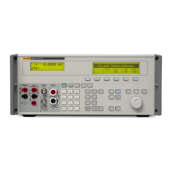
5080A
Calibrator
Advertisement
Table of Contents

Related Manuals for Fluke 5080A


Summary of Contents for Fluke 5080A
- Page 1 Elso Philips Service; tel: +421 32 6582410 email: elso@elso.sk; web: www.elso.sk PN 3502941 April 2010 © 2010 Fluke Corporation. All rights reserved. Specifications are subject to change without notice. All product names are trademarks of their respective companies. http://www.elso.sk...
- Page 2 Fluke authorized resellers shall extend this warranty on new and unused products to end-user customers only but have no authority to extend a greater or different warranty on behalf of Fluke. Warranty support is available only if product is purchased through a Fluke authorized sales outlet or Buyer has paid the applicable international price.
- Page 3 riešenia na presné meranie OPERATOR SAFETY SUMMARY WARNING HIGH VOLTAGE is used in the operation of this equipment LETHAL VOLTAGE may be present on the terminals, observe all safety precautions! To avoid electrical shock hazard, the operator should not electrically contact the output HI or sense HI terminals or circuits connected to these terminals.
- Page 4 riešenia na presné meranie http://www.elso.sk...
-
Page 5: Table Of Contents
Safety Information ..................... 1 Operation Overview................... 3 Where to Go from Here ..................3 Instruction Manuals ................... 4 5080A Operators Manual ................4 5080A Getting Started Manual..............4 How to Contact Fluke ..................4 General Specifications ..................5 Detailed Specifications ..................6 DC Voltage.................... - Page 6 5080A Getting Started Manual http://www.elso.sk...
- Page 7 List of Tables Table Title Page Symbols........................2 Standard Equipment ....................12 Line Power Cord Types Available from Fluke ............16 Current Fuses ......................17 Front-Panel Features ....................19 Rear-Panel Features ....................24 Accessories and Options ..................27 http://www.elso.sk...
- Page 8 5080A Getting Started Manual http://www.elso.sk...
- Page 9 List of Figures Figure Title Page Fuse Access and Line Voltage Selection ............... 15 Line Power Cord Types Available from Fluke ............16 Current Fuse Compartment ..................17 Front-Panel View ....................19 Rear-Panel View ....................24 Accessing the Air Filter..................26...
- Page 10 5080A Getting Started Manual http://www.elso.sk...
-
Page 11: Safety Information
Getting Started WX Warning If the 5080A Calibrator is operated in any way not specified by this manual or other documentation provided by Fluke, the protection provided by the Calibrator may be impaired. The 5080A Calibrator is a fully programmable precision source of the following: •... - Page 12 Go to CAT I connected to mains. Maximum Fluke’s website for recycling transient Overvoltage is as specified by information. terminal markings. This manual contains information, warnings, and cautions that must be followed to ensure safe operation and to maintain the Calibrator in a safe condition.
-
Page 13: Operation Overview
Operation Overview The 5080A Calibrator may be operated at the front panel in the local mode, or remotely using RS-232 or Ethernet ports. For remote operations, several software options are available to integrate 5080A operation into a wide variety of calibration requirements. -
Page 14: Instruction Manuals
5080A Service Manual (PN 3790039) The Operators and Getting Started manuals listed above are shipped with the Calibrator. For ordering instructions, refer to the Fluke Catalog, or ask a Fluke sales representative (see “Service Information” in Chapter 2 of the 5080A Operators Manual). -
Page 15: General Specifications
All specifications are valid after a warm-up period of 30 minutes, or twice the time since last warmed up, to a maximum of 30 minutes. For example, if the 5080A has been turned off for 5 minutes, the warm-up period is 10 minutes. -
Page 16: Detailed Specifications
60 minute period where T is the temperature in °C (room temperature is about 23 °C) and I is the output current in Amps. For example, 17 A at 23 °C could be provided for 60-17-23 = 20 minutes each hour. When the 5080A is outputting currents between 5 and 11 amps for long periods, the internal self-heating reduces the duty cycle. -
Page 17: Resistance
riešenia na presné meranie Calibrator Detailed Specifications Noise Range Bandwidth 0.1 Hz to 10 Hz, p-p Bandwidth 10 Hz to 10 kHz, rms 0 to 329.99 μA 20 nA 60 nA 0 to 3.2999 mA 200 nA 600 nA 0 to 32.999 mA 2 μA 6 μA 0 to 329.99 mA... -
Page 18: Ac Voltage (Sine Wave)
5080A Getting Started Manual AC Voltage (Sine Wave) Specification, tcal ±5 °C Max. Distortion & Noise ±(% of output + μV) Max. 10 Hz to 100 kHz Range Frequency Resolution Burden Bandwidth 90 days 1 year ±(% of output + floor) -
Page 19: Ac Current (Sine Wave)
60 minute period where T is the temperature in °C (room temperature is about 23 °C) and I is the output current in amps. For example, 17 A at 23 °C could be provided for 60-17-23 = 20 minutes each hour. When the 5080A is outputting currents between 5 and 11 amps for long periods, the internal self-heating reduces the duty cycle. -
Page 20: Dc Power Summary
5080A Getting Started Manual DC Power Summary Currents 0.33 to 3.2999 mA 3.3 to 329.99 mA 0.33 to 2.9999 A 3 to 20.5 A Time Voltage Specification, tcal ±5 °C, ±(% of watts output) 90 days 33 mV to 1020 V 0.14... -
Page 21: Phase
riešenia na presné meranie Calibrator Detailed Specifications Phase [1][2] Specification, 1 year, tcal ±5 °C, ±(ΔΦ) 45 TO 65 Hz 65 to 500 Hz 500 Hz to 1 kHz 0.25 ° 1.5 ° 5.0 ° See Power and Dual Output Limit specifications for applicable outputs. Phase settling times are typically <18 seconds additional. -
Page 22: Frequency
If you need to reship the Calibrator, use the original container. If it is not available, you can order a new container from Fluke by identifying the Calibrator’s model and serial number. When you unpack the Calibrator, check for all the standard equipment listed in Table 2. -
Page 23: Service Information
Each Calibrator is warranted to the original purchaser for a period of one year beginning on the date received. The warranty is located at the front of this manual. Factory-authorized service and technical advice for the Calibrator is available at Fluke Service Centers. A complete list of service centers is available at www.fluke.com. -
Page 24: Selecting Line Voltage
You can operate the 5080A Calibrator from one of four line voltage settings: 100 V, 120 V, 220 V, and 240 V (47 Hz to 63 Hz). To check the line voltage setting, note the voltage setting visible through the window in the power line fuse compartment cover (Figure 1). - Page 25 riešenia na presné meranie Calibrator Selecting Line Frequency LINE VOLTAGE INDICATOR CHANGING LINE FUSE CHANGING LINE VOLTAGE nn007f.eps Figure 1. Fuse Access and Line Voltage Selection http://www.elso.sk...
-
Page 26: Rack Mount Considerations
5080A Getting Started Manual Table 3. Line Power Cord Types Available from Fluke Type Voltage/Current Fluke Option Number North America 120 V/15 A LC-1 North America 240 V/15 A LC-2 Universal Euro 220 V/16 A LC-3... - Page 27 4. Remove and check the fuses as necessary. Table lists the part number and rating of each fuse. Table 4. Current Fuses Current Output Fuse Description Fluke Part Number 4A/500V Ultra-Fast Blow (F3) W 3674001 25A/250V Fast Blow (F4) W 3470596 5.
-
Page 28: Warming Up The Calibrator
3. Warming up the Calibrator When you turn on the 5080A, allow a warm-up period of at least 30 minutes for the internal components to stabilize. This ensures that the calibrator meets or exceeds the specifications listed in this manual. - Page 29 Calibrator status. Output values (or potential output values if in standby) are displayed using up to six digits plus a polarity sign. Output frequencies (or potential output frequencies if the 5080A is in standby) are displayed using four digits. Calibrator status is indicated by displaying the following abbreviations: Displayed when an output is active at the front-panel terminals.
- Page 30 The current is changed from ac to dc or from dc to ac. An overload condition is detected. The OPR (Operate) key places the 5080A in operate mode. Operate mode is indicated by “OPR” in the lower left corner of the Output Display and the lit indicator on the OPR key.
- Page 31 The SETUP (Setup Menu) key puts the 5080A in the setup mode, displaying the setup menu in the Control Display. Setup options can be selected using the softkeys under the Control Display.
- Page 32 ENTER with no value restores the output to the value of the reference. Output Units Keys The output units keys determine the function of the 5080A. Some keys have a second unit if the SHIFT key is pressed just before the units key. The output units are as follows: Volts or Decibels relative to 1 mW into 600 ohms (impedance changeable).
- Page 33 riešenia na presné meranie Calibrator Rear-Panel Features gew325f.eps Figure 5. Front-Panel View (cont.) Table 4. Front-Panel Features (cont.) The I (Polarity) key changes the polarity of the output for dc voltage or dc current functions. Press the I key then E to toggle the output polarity. The MegOhm terminals are used for high resistance sourcing.
- Page 34 The Fan Filter covers the air intake to keep dust and debris out of the chassis air baffles. The 5080A fan provides a constant cooling air flow throughout the chassis. See “How to Clean the Air Filter” in this manual for Instructions.
-
Page 35: How To Clean The Air Filter
AUX EARTH GROUND terminal for a protective grounding wire. The AUX EARTH GROUND terminal is internally grounded to the chassis. If the 5080A is the location of the ground reference point in a system, this binding post can be used for connecting other instruments to earth ground. -
Page 36: General Cleaning
5080A Getting Started Manual reinstalling it. 4. Reinstall the filter element by performing the filter removal steps in reverse order. oq062f.eps Figure 6. Accessing the Air Filter General Cleaning For general cleaning, wipe the case, front-panel keys, and lens using a soft cloth slightly dampened with water or a non-abrasive mild cleaning solution that does not harm plastics. -
Page 37: Accessories And Options
MET/TRACK) Manual Calibration Software. MET/BASE and MET/TRACK required. Manual MET/CAL Options can be ordered factory installed with a new Calibrator (5080A/MEG, 5080A/SC, and 5080A/SC/MEG), or added later at a Fluke service center for an additional installation and calibration charge. http://www.elso.sk... - Page 38 5080A Getting Started Manual http://www.elso.sk...
Need help?
Do you have a question about the 5080A and is the answer not in the manual?
Questions and answers