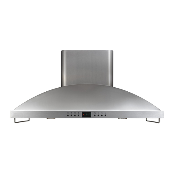
Monogram ZV1050 Installation Instructions Manual
42" island
vent hood
Hide thumbs
Also See for ZV1050:
- Installation instructions manual (16 pages) ,
- Technical data sheet (2 pages) ,
- Manual (2 pages)
Table of Contents
Advertisement
Quick Links
Download this manual
See also:
Owner's Manual
Advertisement
Table of Contents

Related Manuals for Monogram ZV1050


Summary of Contents for Monogram ZV1050
- Page 1 Installation Instructions 42" Island Vent Hood ZV1050 monogram.com...
-
Page 2: Safety Information
Safety Information BEFORE YOU BEGIN WARNING: Read these instructions completely and carefully. TO REDUCE THE RISK OF FIRE, ELECTRICAL SHOCK OR INJURY TO PERSONS, OBSERVE THE FOLLOWING: – Save these instructions for local A. Use this unit only in the manner intended by the inspector’s use. -
Page 3: Product Dimensions
Design Information CONTENTS Design Information ..........................................................................Step 6, Secure Wiring .......................... Tools and Materials Required ............5 ..........................5 ................................... 6 ............. Installation Instructions ......................................PRODUCT DIMENSIONS DUCT COVER ACCESSORIES mounted installations. -
Page 4: Determine Installation Height
25-1/2" to 30" ZX10510SFSS 9'8" 25-1/2" to 30" ZX10510SFSS DUCT COVER DIMENSIONS 9'9" 25-1/2" to 30" ZX10510SFSS 9'10" 25-1/2" to 30" ZX10510SFSS 9'11" 25-1/2" to 30" ZX10510SFSS 10'0" 25-1/2" to 30" ZX10510SFSS ZV1050 11-1/2" 12" ZX1059 19" 20" ZX10510 25" 26"... - Page 5 POWER SUPPLY TOOLS AND MATERIALS REQUIRED (not supplied) IMPORTANT – Please read carefully. WARNING: FOR PERSONAL SAFETY, THIS APPLIANCE MUST BE PROPERLY GROUNDED. AVERTISSEMENT : POUR DES RAISONS DE SÉCURITÉ, CET APPAREIL DOIT ÊTRE CORRECTEMENT MIS À LA TERRE. Remove house fuse or open circuit breaker before beginning installation.
- Page 6 Total DUCT FITTINGS Duct Piece Dimensions Length* Used Length This Hood Must Use 8" Round Duct. It Can Transition to 3-1/4" x 12" Duct. permissible lengths for duct runs to outdoors. NOTE: sible equivalent lengths! Maximum duct length: 100 ft. for range hoods.
-
Page 7: Installation Instructions
Installation Instructions STEP 1 CONSTRUCT CEILING SUPPORT Ceiling Plan the location Hood Ducting Centerline the cooking appliance. See illustration. Hood surface and bottom of hood. Front 15-3/4" 31-1/2" Approx. 1-1/2" Cooktop Beyond Cooking Surface Countertop Side View Ceiling support structure ing structure. - Page 8 Installation Instructions STEP 1 CONSTRUCT CEILING SUPPORT (cont.) EXAMPLE B Spacing Symmetrically About 8" Duct Cooktop Outline Center of Cooktop Front of Hood EXAMPLE C Symmetrically About 8" Duct Spacing Center of Cooktop Cooktop Outline Front of Hood...
- Page 9 Installation Instructions STEP 1 CONTINUED for the two supports. The cross-framing must be accurately aligned to ensure correct positioning of the hood. Check with a spirit level and adjust if necessary. IMPORTANT: The ceiling structure must be capable of sup- porting the weight of the hood (approximately 300 pounds) frame will be supported by the 2 x 4 min.
- Page 10 Installation Instructions STEP 2 REMOVE THE PACKAGING The vent hood is packed separately from the decorative STEP 3 CHECK INSTALLATION HARDWARE AND ACCESSORIES hood and check contents. 11-1/4” TO CENTER LINE OF HOLES 7-1/4” TO WIRE WIRE HOLE CENTER LINE HOLE ACCESS ACCESS...
- Page 11 Installation Instructions STEP 4 MOUNT TEMPLATE in place. – Be sure the template is oriented correctly, with the front of the hood. vide parallel alignment with the countertop below. Wire Access Holes access hole. STEP 5 INSTALL SUPPORT FRAME Hood Lower Support Mounting Flange...
- Page 12 Installation Instructions STEP 6 SECURE WIRING STEP 7 SIZE AND INSTALL DUCTWORK below the support. Ceiling Left Side View Support Frames Tape House Wiring frame (Dim. A). prevent damage during installation and service. the frame to determine required duct length. NOTE: connection to the top of the hood.
-
Page 13: Step 8 Install Decorative Duct Covers
Installation Instructions STEP 8 INSTALL DECORATIVE DUCT COVERS Right Side duct and push to the top. on the support frame. This will make screw installation easier. a stop screw and prevent the lower decorative duct cover from sliding down. in the top. CAUTION: and push to the ceiling. - Page 14 Installation Instructions STEP 11 SLIDE DUCT COVER DOWN STEP 10 CONNECT ELECTRICAL WARNING: with a ground wire, a ground must be provided by the installer. When house wiring is aluminum, be sure to use copper connectors. AVERTISSEMENT : Si le câblage de de la maison sont en aluminium, il prendre soin d’utiliser all wire harnesses out of the path of the duct cover seating.
- Page 15 Installation Instructions STEP 12 INSTALL FILTERS, FINALIZE INSTALLATION Filter Slots lower slots at the rear of the see if the red light is glowing in the display. If the red check that house wires have been connected securely and that no wires have been damaged during installation.
- Page 16 Note: While performing installations described in this For Monogram local service in your area, call ® 1.800.444.1845. Note: General Electric. Therefore, materials, appearance and Printed in Italy...
Need help?
Do you have a question about the ZV1050 and is the answer not in the manual?
Questions and answers