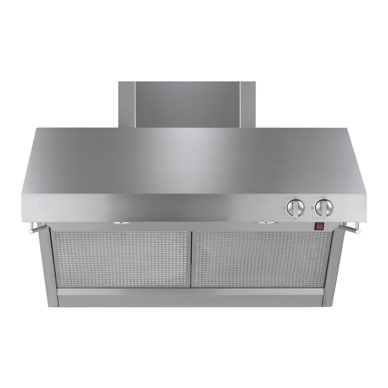
Monogram ZV48R Installation Instructions Manual
30”, 36” and 48” professional restaurant style vent hoods
Hide thumbs
Also See for ZV48R:
- Installation instructions manual (18 pages) ,
- Installation instructions manual (16 pages) ,
- Installation instructions manual (16 pages)

Related Manuals for Monogram ZV48R


Summary of Contents for Monogram ZV48R
- Page 1 INSTALLATION INSTRUCTIONS 30”, 36” and 48” Professional Restaurant Style Vent Hoods Monogram.com...
-
Page 2: Safety Information
■ C ompletion Time — 1 to 3 Hours. ONLY. DO NOT USE TO EXHAUST HAZARDOUS MATERIALS, EXPLOSIVE MATERIALS OR VAPORS. ■ P roper installation is the responsibility of the installer. Product failure due to improper installation WARNING TO REDUCE THE RISK OF FIRE, is not covered under the warranty. ELECTRICAL SHOCK OR INJURY TO PERSONS, ■ F or Monogram local service in your area, call OBSERVE THE FOLLOWING: 1.800.444.1845. ■ I nstallation work and electrical wiring must be done by ■ F or Monogram service in Canada, call qualified person(s) in accordance with all applicable 1.800.561.3344. codes and standards, including fire-rated construction. ■ F or Monogram Parts and Accessories, call ■ S ufficient air is needed for proper combustion and... -
Page 3: Table Of Contents
Hoods may be Warming installed with Shelf the shelf or backguard alone, or with both as u a r d shown. B a c k g Model ZV48R Model ZV36R Model ZV30R 1” = 2.5 cm; 1’ = 0.3 m 49-80152 Rev. 8... -
Page 4: Installation Clearances
12" Duct Cover to be sure standard is applicable. Soffit Installation S O F F IT S O F F IT 6" Duct Covers Hood Model 6” Duct Cover Dimensions ZV48R ZX48DC6 6"H x 19-11/16"W x 11-7/8"D 30" Min. 32" Min. 36" Max. 38" Max. ZV36R ZX36DC6 6"H x 15-3/4"W x 11-7/8"D... -
Page 5: Installation Height, Duct Cover Accessories
Advance Planning DETERMINE INSTALLATION HEIGHT, DUCT COVER ACCESSORIES These vent hoods must be installed Restaurant-Style Hoods without Restaurant-Style Hoods with Shelf 30” min. to 36” max. above the Warming Shelf Installed Installed standard 36” high cooking surface. *Possible *Possible Actual Hood 6” Duct 12” Duct Hood 6”... -
Page 6: Power Supply
Advance Planning ADVANCE PLANNING POWER SUPPLY Ductwork Planning IMPORTANT - (Please read carefully) ■ T hese vent hoods are equipped for 10” round WARNING FOR PERSONAL SAFETY, THIS ductwork. For best performance, use 10” round APPLIANCE MUST BE PROPERLY GROUNDED. ductwork on the 48” wide hoods. 30” and 36” hoods may be transitioned to 8” round. Remove house fuse or open circuit breaker before beginning installation. -
Page 7: Duct Fittings
Advance Planning DUCT FITTINGS Total Equivalent Quantity Equivalent Duct Piece Dimensions Length* Used Length Hoods Are Equipped 10" round 5 ft. For 10" Round Duct to 8" round Use this chart to compute maximum permissible lengths Round, 1 ft. (per foot for duct runs to outdoors. straight length) For best results, use 10" diameter duct. -
Page 8: Remove The Packaging
Installation Preparation REMOVE THE PACKAGING ■ R emove packages ■ G rease filters must be Duct from the "V" shaped removed. Grasp the Transition cardboard section. latch, pull the filter up Wood Mounting Parts Remove shipping pads. Hood and lift out. Support ■ L ift the hood out of the box. ■ L ift to remove the Motor grease trays. Set Mounted IMPORTANT: Lift the hood on Skid... - Page 9 Installation Instructions DETERMINE HOOD, DUCTWORK AND WIRING LOCATIONS ■ U se a level to draw the cooktop centerline location. Draw the line to ceiling height. 9-7/8" ■ M easure desired distance from the bottom of the hood to the cooking surface. Top of Hood NOTE: If you are installing the hood with duct covers, be sure to read “Using Duct Cover Accessories” page 4. Wood Exact installation height may be determined by use of 22-1/2" Support 20" one or more duct covers. *House Wiring ■ D etermine bottom Location...
- Page 10 Installation Instructions INSTALL HOOD ONTO WALL IMPORTANT: Framing must be capable of supporting up to 150 lbs. SKIP THIS STEP IF INSTALLING BENEATH A SOFFIT OR CABINET, GO TO STEP 2B. Install Transition Onto Top of Hood ■ L ocate at least 2 vertical studs at the wood support. IMPORTANT: Remove ■ C enter the supplied wood support, left to right and shipping tape from damper below the 20"...
- Page 11 “A” Centerline to Stud “B” Hood Width At and Keyhole Slots the Top protrude 1/4". The 1/4" gap will provide clearance to engage the keyhole slots in the top of the hood. ZV48R 23-9/16" 47-15/16" ZV48R 17-9/16" 35-15/16" ■ L ift hood to installation position. Locate house wiring ZV36R 14-9/16"...
- Page 12 Installation Instructions CONNECT DUCTWORK INSTALL DUCT COVERS ■ I nstall ductwork, making connections in direction of NOTE: For easier handling, remove cardboard insert airflow as illustrated. after film is peeled off. ■ S ecure joints in ductwork with sheetmetal screws. Remove protective film from duct covers. If more than one duct cover is used, secure each piece together ■ W rap all duct joints with screws provided. with duct tape for an airtight seal.
- Page 13 Installation Instructions INSTALL FILTERS ■ D rop grease tray into the hood. The rear tabs should ■ I nsert the grease filter into the opening and drop into engage the slots in the hood track. the bottom. Raise filter to the top and lock into place. ■ T o remove the filters, grasp the handle, push the filter up and lift out. INSTALL BACKGROUND AND SHELF INSTALL BACKGUARD This hood can be installed with the warming shelf and backguard together or with the warming shelf or ■ R emove packaging.
-
Page 14: Step 9, Install Shelf Only
Installation Instructions INSTALL SHELF "ONLY" INSTALL IMPLEMENT RODS ■ R emove shelf packaging and protective film. ■ I f installing the shelf alone, without the backguard, place shelf against the bottom of the hood and mark the screw hole locations "B" on the wall. ■ D rill two 1/8" pilot holes. ■ I f the drill did not enter the studs, enlarge holes to 3/8". Screw ■ I nsert the wall anchors into the enlarged holes. Stand-offs Remove the screws from the wall anchors. - Page 15 Notes 49-80152 Rev. 8...
- Page 16 NOTE: While performing installations described in this book, safety glasses or goggles should be worn. For Monogram local service in your area, call ® 1.800.444.1845. NOTE: Product improvement is a continuing endeavor at GE Appliances. Therefore, materials, appearance and specifications are subject to change without notice. 49-80152 Rev. 8 05-19 GEA Printed in Mexico...
- Page 17 INSTRUCTIONS D'INSTALLATION Hottes professionnelles de type restaurant de 30 po, 36 po et 48 po T O U T É L E V E R Monogram.com...
- Page 18 La panne du produit due à une mauvaise installation n'est D'INCENDIE, DE DÉCHARCHE ÉLECTRIQUE OU DE pas couverte par la garantie. BLESSURES, SUIVEZ LES CONSIGNES SUIVANTES : ■ P our le service à la clientèle Monogram dans votre ■ L 'installation et le câblage électrique doivent être effectués région, appelez le 1-800-444-1845. par une personne qualifiée et conformément à tous les codes et toutes les normes applicables, incluant les règlements ■ P our le service à la clientèle Monogram au Canada,...
- Page 19 D o s s e ou avec les deux comme illustré. 47-15/16 po 25 po Modèle ZV48R 12 po 29-15/16 po 12 po 35-15/16 po 10 po 10 po 22-1/2 po...
-
Page 20: Dégagements Pour L'installation
R E T O M B É E D R E T O M B É E D la hotte de 6 po Dimensions E P LA F O N D E P LA F O N D ZV48R ZX48DC6 H 6 po x L 19-11/16 po x P 11-7/8 po ZV36R ZX36DC6 H 6 po x L 15-3/4 po x P 11-7/8 po ZV30R... -
Page 21: Hauteur D'installation, Cache-Conduits
Préparatifs DÉTERMINER LA HAUTEUR D'INSTALLATION ET LES CACHE-CONDUITS Ces hottes doivent être installées à une Hottes de style restaurant sans Hottes de style restaurant avec hauteur minimale de 30 po et maximale de tablette de réchaud tablette de réchaud 36 po au-dessus de la surface de cuisson * Hauteur * Hauteur standard de 36 po de hauteur. -
Page 22: Planification Préliminaire
Préparatifs PLANIFICATION PRÉLIMINAIRE ALIMENTATION ÉLECTRIQUE Préparatifs relatifs aux conduits d'évacuation IMPORTANT – (veuillez lire attentivement) ■ C es hottes de ventilation sont conçues pour des conduits AVERTISSEMENT POUR VOTRE SÉCURITÉ, CET ronds de 10 po. Pour un meilleur rendement d'évacuation, APPAREIL DOIT ÊTRE CORRECTEMENT MIS À LA TERRE. utilisez des conduits ronds de 10 po sur les hottes de 48 po de large. Les hottes de 30 po et 36 po peuvent Enlevez le fusible ou déclenchez le disjoncteur au panneau s'adapter à... -
Page 23: Raccords De Conduit
Préparatifs RACCORDS DE CONDUIT Longueur Section de Longueur Quantité équivalente conduit Dimensions équivalente* utilisée totale Ces hottes sont conçues pour Rond de 10 po 5 pi des conduits ronds de 10 po. à rond de 8 po Utilisez ce tableau pour calculer la longueur maximale Rond, droit 1 pi (par pied admissible du conduit vers l'extérieur. -
Page 24: Déballage
Préparatifs avant l'installation DÉBALLAGE ■ R etirez les emballages de ■ L es filtres à graisse Conduit de la section en carton en doivent être retirés. Pour transition forme de « V ». Retirez ce faire, saisissez le Support l'emballage de protection. loquet, tirez le filtre vers le de fixation Pièces Hotte en bois haut et soulevez-le. -
Page 25: Des Conduits Et Du Câblage
Instructions d'installation DÉTERMINER LES EMPLACEMENTS D'INSTALLATION DE LA HOTTE, DES CONDUITS ET DU CÂBLAGE ■ U tilisez un niveau pour tracer l'emplacement de la ligne centrale de la surface de cuisson. Tracez la 9-7/8 po ligne jusqu'au plafond. ■ M esurez la distance désirée entre le bas de la hotte Haut de la hotte et la surface de cuisson. - Page 26 Instructions d'installation INSTALLER LA HOTTE SUR LE MUR IMPORTANT : La charpente doit pouvoir soutenir une SAUTEZ CETTE ÉTAPE SI L'INSTALLATION EST charge de 150 lb (68 kg). EFFECTUÉE SOUS UNE RETOMBÉE DE PLAFOND OU SOUS UNE ARMOIRE – PASSEZ À L'ÉTAPE 2B. Installer le conduit de transition sur le dessus de la hotte ■ L ocalisez au moins 2 montants verticaux pour le support en bois.
- Page 27 1/4 po. Cette saillie de 1/4 po permet d'engager les vis du montant aux encoches la hotte en haut dans les encoches en trou de serrure de la partie supérieure en trou de serrure de la hotte. ZV48R 23-9/16 po 47-15/16 po ■ S oulevez la hotte en position d'installation. Localisez le ZV48R 17-9/16 po 35-15/16 po câblage de la maison et acheminez-le à...
- Page 28 Instructions d'installation RACCORDER LE CONDUIT INSTALLER LES CACHE-CONDUITS ■ I nstallez le conduit selon la direction du débit d'air, REMARQUE : Pour une manipulation plus facile, retirez la comme illustré. pièce en carton une fois le film décollé. ■ R accordez les joints dans les conduits avec des vis à tôle. Enlevez le film protecteur des couvre-conduits. Si plus d'un cache-conduit est utilisé, fixez chaque pièce avec ■ E nveloppez tous les les vis fournies.
- Page 29 Instructions d'installation INSTALLER LES FILTRES ■ D éposez le plateau à graisse dans la hotte. Les languettes ■ I nsérez le filtre à graisse dans l'ouverture et laissez-le arrière doivent s'engager dans les encoches du rail de la hotte. tomber dans le fond. Soulevez le filtre vers le haut et verrouillez-le en place. ■ P our retirer les filtres, saisissez la poignée, poussez le filtre vers le haut et soulevez-le. INSTALLER LE DOSSERET ET LA TABLETTE INSTALLER LE DOSSERET Cette hotte peut être installée avec la tablette de réchaud et le dosseret ou avec seulement la tablette de réchaud...
- Page 30 Instructions d'installation INSTALLER LES TIGES INSTALLER LA TABLETTE D'USTENSILES UNIQUEMENT ■ R etirez l'emballage et le film protecteur de la tablette. ■ S i vous installez uniquement la tablette sans le dosseret, placez la tablette contre le bas de la hotte et marquez les emplacements des trous de vis « B » sur le mur. ■ P ercez deux avant-trous de 1/8 po. ■ S i le foret n'est pas entré dans les montants, élargissez Vissez les les trous à...
- Page 31 Notes 49-80152 Rév. 8...
- Page 32 REMARQUE : Lors de la procédure d'installation décrite dans ce manuel, il est recommandé de porter des lunettes de sécurité. Pour joindre le service à la clientèle de Monogram dans votre région, appelez le 1-800-444-1845. REMARQUE : L'amélioration des produits est une préoccupation constante chez Électroménagers GE. Par conséquent, les matériaux, l'apparence et les spécifications peuvent être modifiés sans préavis.
Need help?
Do you have a question about the ZV48R and is the answer not in the manual?
Questions and answers