Monogram ZV1050 Installation Instructions Manual
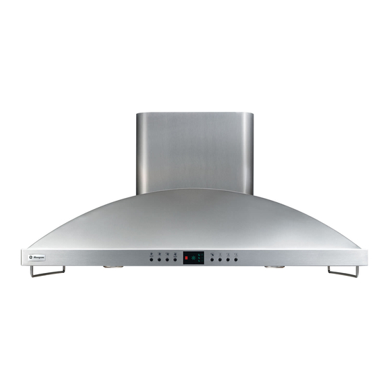
42” island vent hood
Hide thumbs
Also See for ZV1050:
- Installation instructions manual (16 pages) ,
- Technical data sheet (2 pages) ,
- Manual (2 pages)
Advertisement
Quick Links
Advertisement

Subscribe to Our Youtube Channel
Related Manuals for Monogram ZV1050


Summary of Contents for Monogram ZV1050
- Page 1 INSTALLATION INSTRUCTIONS 42” Island Vent Hood ZV1050 MONOGRAM.COM...
- Page 2 éviter la mise sous tension is not covered under the warranty. accidentelle. S’il n’est pas possible de verrouiller le étiquette très visible au panneau. monogram.com. monogram.ca monogram.com/use-and-care/parts. wiring must be done by qualified person(s) in accordance with all applicable codes and standards CAUTION including fire-rated construction.
- Page 3 Design Information CONTENTS Design Information ................. 3 ..........11 ................. 11 Determine Installation Height ..................12 ....... 12 Tools and Materials Required ........5 ....... 13 ..............5 ............. 13 ..............6 ......... Installation Instructions ................
- Page 4 25-1/2" to 30" ZX10510SFSS 9'6" 25-1/2" to 30" ZX10510SFSS DUCT COVER DIMENSIONS 9'7" 25-1/2" to 30" ZX10510SFSS 9'8" 25-1/2" to 30" ZX10510SFSS ZV1050 Duct Cover 9'9" 25-1/2" to 30" ZX10510SFSS Dimensions 9'10" 25-1/2" to 30" ZX10510SFSS Model 9'11" 25-1/2" to 30" ZX10510SFSS 11-1/2"...
- Page 5 Advance Planning TOOLS AND MATERIALS REQUIRED POWER SUPPLY (not supplied) IMPORTANT - (Please read carefully) • Tape measure WARNING • Knife • Spirit level AVERTISSEMENT Remove house fuse or open circuit breaker before beginning installation. • Hammer prevailing local codes and ordinances. •...
- Page 6 Advance Planning DUCT FITTINGS Total Equivalent Quantity Equivalent This Hood Must Use an 8” Round Duct Piece Dimensions Length* Used Length Duct. It Can Transition to a 1 ft. (per foot 3-1/4” x 12” Duct. straight length) 1 ft. (per foot straight length) for duct runs to outdoors.
- Page 7 Installation Preparation CONSTRUCT CEILING SUPPORT Plan the location Ceiling Hood Ducting Use a plumb bob to check location to be sure Centerline countertop/cooktop location below the hood will align Hood front edge of the cooking appliance. See illustration. Front 15-3/4" cooking surface and bottom of hood.
- Page 8 Installation Preparation CONSTRUCT CEILING SUPPORT (cont.) EXAMPLE B Spacing Duct/Cooktop Centerline 8" Duct Cooktop Center of Cooktop Outline Front of Hood EXAMPLE C Duct/Cooktop Centerline 8" Duct Spacing Center of Cooktop Cooktop Outline Front of Hood 31-14899 Rev. 3...
- Page 9 Installation Instructions CONSTRUCT CEILING SUPPORT (cont.) screws total for the two supports. ensure correct positioning of the hood. Check with a spirit level and adjust if necessary. IMPORTANT: The ceiling structure must be capable of supporting the weight of the hood (approximately 300 pounds) and any inadvertent user contact loads.
- Page 10 Installation Instructions REMOVE THE PACKAGING The vent hood is packed separately from the decorative CHECK INSTALLATION HARDWARE AND ACCESSORIES Locate the hardware accessory pack shipped with the hood and check contents. 11-1/4” TO CENTER LINE OF HOLES 7-1/4” TO WIRE WIRE HOLE CENTER LINE...
- Page 11 Installation Instructions MOUNT TEMPLATE tape in place. front of the hood. Use a plumb bob to be sure the mounting holes will provide parallel alignment with the countertop below. Center-punch all hole locations. Wire Access Holes access hole. INSTALL SUPPORT FRAME Hood Lower Support Mounting...
- Page 12 Installation Instructions SECURE WIRING SIZE AND INSTALL DUCTWORK Ceiling Left Side View Support Frames Tape House Wiring prevent damage during installation and service. of the frame to determine required duct length. NOTE: (female) connection to the top of the hood. The installation of the hood.
- Page 13 Installation Instructions INSTALL DECORATIVE DUCT COVERS Right Side on the support frame. This will make screw installation upper duct and push to the top. easier. the upper (inner) duct cover. The decorative screw will act as a stop screw and prevent the lower decorative holes in the top.
- Page 14 Installation Instructions CONNECT ELECTRICAL SLIDE DUCT COVER DOWN Verify that power is turned off at the source. WARNING If house wiring is not 2-wire with aluminum-to-copper connectors. AVERTISSEMENT Si le câblage de la maison des connecteurs pour l’aluminium-cuivre. decorative stop screw from the support frame. Dress all wire harnesses out of the path of the duct cover seating.
- Page 15 Installation Instructions INSTALL FILTERS, FINALIZE INSTALLATION Filter Slots opening. Lift the filter and pull the knob forward until the filter rests on the slots. by checking to see if the red light is glowing in the filter until the red indicator light turns off. cleaner.
- Page 16 NOTE: safety glasses or goggles should be worn. ® monogram.com. NOTE: and specifications are subject to change without notice. 31-14899 Rev. 3 10-19 GEA Printed in Italy...
Need help?
Do you have a question about the ZV1050 and is the answer not in the manual?
Questions and answers