BendPak HD-9 Series Installation And Operation Manual
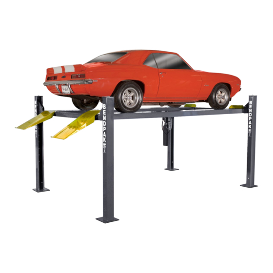
Four-post lift
Hide thumbs
Also See for HD-9 Series:
- Installation and operation manual (72 pages) ,
- Service manual (31 pages) ,
- Installation and operation manual (50 pages)
Table of Contents
Advertisement
Installation and Operation Manual
Models:
• HD-9
• HD-9ST
• HD-9XL
• HD-9STX
• HD-9XW
• HD-9EWT
Original instructions in
the English language
Designed and engineered by BendPak Inc. in Southern California, USA. Made in China.
________________________________________________________________________________________________
IMPORTANT Safety Instructions, save these instructions! Read the entire
contents of this manual before using this product. Failure to follow the instructions and
safety precautions in this manual can result in severe injury or death. Make sure all other
operators also read this manual. Keep the manual near the product for future reference.
proceeding with setup and operation, you agree that you fully understand the
contents of this manual and assume full responsibility for product use.
HD-9 Four-Post Lift
Manual P/N 5900123 — Manual Revision N2 — November 2023
⚠
DANGER
1645 Lemonwood Dr.
Santa Paula, CA 93060 USA
Toll Free: (800) 253-2363
Tel: (805) 933-9970
bendpak.com
HD-9ST shown.
By
Advertisement
Table of Contents

Related Manuals for BendPak HD-9 Series


Summary of Contents for BendPak HD-9 Series
- Page 1 • HD-9XW • HD-9EWT Original instructions in HD-9ST shown. the English language Designed and engineered by BendPak Inc. in Southern California, USA. Made in China. ⚠ ________________________________________________________________________________________________ DANGER IMPORTANT Safety Instructions, save these instructions! Read the entire contents of this manual before using this product. Failure to follow the instructions and safety precautions in this manual can result in severe injury or death.
- Page 2 Copyright. Copyright © 2023 by BendPak Inc. All rights reserved. You may make copies of this document if you agree that: you will give full attribution to BendPak Inc., you will not make changes to the content, you do not gain any rights to this content, and you will not use the copies for commercial purposes.
- Page 3 Unit Information. Enter the Model Number, Serial Number, and the Date of Manufacture from the label on your unit. This information is required for part or warranty issues. Model: Serial: Date of Manufacture:...
-
Page 4: Table Of Contents
HD-9EWT. This lift is similar to the HD-9XW, but more than 6 inches wider. Better • accommodates wide cars and off-road vehicles. This manual is mandatory reading for all users of the HD-9 Series, including anyone who installs, uses, maintains, repairs, or wants to know more about them. ⚠... -
Page 5: Shipping Information
900 chemicals identified by the State of California to cause cancer, birth defects or reproductive harm. ALWAYS use this product in accordance with BendPak BendPak’s instructions. For more information go to www.P65Warnings.ca.gov. - Page 6 Installation and Service for more information about safely installing, using, and servicing your Lift. 27. HD-9 Series Lifts are four post vehicle lifts. Use them only for their intended purpose. 28. You must wear OSHA-approved (publication 3151) personal protective equipment at all times when installing, using, maintaining, or repairing the Lift.
- Page 7 Instead, take it out of service, then contact an authorized repair facility, your dealer, or BendPak at (800) 253-2363, option 7, then (4 for Service) and (5 for Parts), or email support@BendPak.com.
-
Page 8: Components
Ladders-Sections of steel that are installed at the back of each Post; these are part of the Safety Lock system. • Wheel Chocks- Always place at least two suitable wheel chocks behind each rear tire, so that the vehicle cannot roll backward from Lift. HD-9 Series Four-Post Lifts P/N 5900123 — Rev. N2 — November 2023... - Page 9 • Aluminum Drive-up Ramps. The Aluminum Drive-up Ramps are a low-profile alternative to the standard Drive-up Ramps that are delivered with your Lift. See the Aluminum Approach Ramps page on the BendPak website for more information. • Aluminum Platforms. Aluminum Platforms fill in the open space between the Lift’s two Runways, preventing liquids from dripping on the floor or onto a Vehicle below the Runways.
-
Page 10: Specifications
Specifications HD-9 Series Four-Post Lifts P/N 5900123 — Rev. N2 — November 2023... - Page 11 For example, the maximum weight allowed on the Lift for a Vehicle with a wheelbase of 85 in. is 50 percent of the Lift’s rated capacity (or 4,500 lbs. when the rated capacity is 9,000 lbs.). Specifications subject to change without notice. HD-9 Series Four-Post Lifts P/N 5900123 — Rev. N2 — November 2023...
- Page 12 Lift for a Vehicle with a wheelbase of 85 in. is 50 percent of the Lift’s rated capacity (or 4,500 lbs. when the rated capacity is 9,000 lbs.). Specifications subject to change without notice. HD-9 Series Four-Post Lifts P/N 5900123 — Rev. N2 — November 2023...
-
Page 13: Faqs
Q: Does the Lift have to be anchored in place? A: Yes, BendPak strongly recommends that you anchor the Lift; it may be less stable if you do not anchor the Bases, and you could possibly void ALI certification. If you plan to use the optional Rolling Bridge Jack, the Lift must be anchored. -
Page 14: Installation Checklist
☐ 34. Anchor the Posts. ☐ 35. Perform final leveling. ☐ 36. Install the Accessories. ☐ 37. Lubricate the Lift. ☐ 38. Test the Lift. ☐ 39. Review the final checklist. HD-9 Series Four-Post Lifts P/N 5900123 — Rev. N2 — November 2023... -
Page 15: Installation
Only fully trained personnel should be involved in installing this equipment. Pay attention at all times. Use appropriate tools and lifting equipment. Stay clear of moving parts. BendPak recommends referring to the current version of the ANSI/ALI ALIS Standard Safety Requirements for Installation and Service for more information about safely installing, using, and servicing your Lift. - Page 16 Use the maximum lifting height of your Lift model plus the height of the tallest Vehicle you plan on raising to determine how much height you will need at the Lift location. HD-9 Series Four-Post Lifts P/N 5900123 — Rev. N2 — November 2023...
- Page 17 28 days. ⚠ CAUTION BendPak lifts are supplied with installation instructions and Concrete anchors that meet the criteria set by the current version of the American National Standard “Automotive Lifts – Safety Requirements for Construction, Testing, and Validation”, ANSI/ALI ALCTV.
- Page 18 Power Post (which holds the Power Unit) near the power source. If power is not an issue, choose the option below that best fits your setup. HD-9 Series Four-Post Lifts P/N 5900123 — Rev. N2 — November 2023...
- Page 19 Posts into position. Hydraulic Cylinder is underneath the Powerside Runway. Drive-up Ramps are not affected by Power Post location. Not to scale. Not all components shown. HD-9 Series Four-Post Lifts P/N 5900123 — Rev. N2 — November 2023...
- Page 20 2. Create the two Side Chalk Lines at 90° angles to the Front Chalk Line and parallel to each other. Make the Side Chalk Lines longer (about 12 inches on each end) than the Outside Length setting. The Side Chalk Lines must be parallel to each other. HD-9 Series Four-Post Lifts P/N 5900123 — Rev. N2 — November 2023...
- Page 21 Do not stand up the Posts yet; some of the following procedures are easier and much safer to complete if the Posts are lying on the ground. HD-9 Series Four-Post Lifts P/N 5900123 — Rev. N2 — November 2023...
- Page 22 (the Runway with the Hydraulic Cylinder). The following drawing shows the two Crosstube setups based on the Power Post location. Top View. Not to scale. Some components not shown or exaggerated for clarity. HD-9 Series Four-Post Lifts P/N 5900123 — Rev. N2 — November 2023...
- Page 23 Post, orient the Slide Blocks over the openings in the Post, then slide the Crosstube down. 4. Perform Steps 2 and 3 for the other Crosstube. HD-9 Series Four-Post Lifts P/N 5900123 — Rev. N2 — November 2023...
- Page 24 Safety for the broken Cable immediately engages, preventing the Runways from falling. The Slack Safety Locks become engaged during installation when you raise the Crosstubes (see Raising the Crosstubes). Make sure to disengage them immediately after raising the Crosstubes. HD-9 Series Four-Post Lifts P/N 5900123 — Rev. N2 — November 2023...
- Page 25 Safety Locks on your Lift may not hold the weight of a Vehicle, putting anyone under the Lift in danger. Top and Side view. Not necessarily to scale. Not all components shown. HD-9 Series Four-Post Lifts P/N 5900123 — Rev. N2 — November 2023...
- Page 26 You are looking for about an inch of thread above the top of the Top Nut. Note: The other hole in the middle of the Top Cap is for the Lifting Cable, installed later. 6. Install the remaining Top Caps the same way. HD-9 Series Four-Post Lifts P/N 5900123 — Rev. N2 — November 2023...
- Page 27 Crosstube, then release the Sheave or Steel Arm. 3. Disengage the other three Slack Safety Locks as done in Step 2. HD-9 Series Four-Post Lifts P/N 5900123 — Rev. N2 — November 2023...
- Page 28 8. Use a Transit Level to estimate the Shim requirements: use a target to find the difference in height between the Posts. The difference is the estimated Shim thickness. Do not use Shims and/or Anchor Bolts to shim more than 1/2 inch. HD-9 Series Four-Post Lifts P/N 5900123 — Rev. N2 — November 2023...
- Page 29 When you remove the Sheaves, keep the components together. You will be reinstalling them at the same location, using the same components. Drawing combines Top and Side views. Not necessarily to scale. Not all components shown. HD-9 Series Four-Post Lifts P/N 5900123 — Rev. N2 — November 2023...
- Page 30 Flex Tube (which holds the Air, Return, and Hydraulic Hose). The following drawing shows the correct orientation of the Runways for both Power Post locations. Top View. Not drawn to scale. Not all components shown. HD-9 Series Four-Post Lifts P/N 5900123 — Rev. N2 — November 2023...
- Page 31 M12 x 25 mm Bolt, M12 Washer, and M12 Nut. The following drawing shows how to install the Runway Strap. Runway Strap goes inside Runway Rails. Not drawn to scale. Not all components shown. HD-9 Series Four-Post Lifts P/N 5900123 — Rev. N2 — November 2023...
- Page 32 Four-Post Lift Flex Tube Kit The following provides installation guidance for the Flex Tube Kit (5216139) on HD-9 Series four-post Lifts. The Flex Tube is designed to route and protect Hydraulic, Pneumatic and in some cases Electrical lines from becoming entrapped and damaged under a Lift Platform.
- Page 33 Before routing the Lifting Cables on your Lift, you need to know the following: • BendPak strongly recommends using protective gloves when working with the Lifting Cables. • Each Lift has four Lifting Cables of varying lengths and can only make one connection.
- Page 34 Lifting Cables, A and B pass around one Cable Sheave and one Gusset Sheave. Lifting Cables C and D pass around two Cable Sheaves and one Gusset Sheave. See the drawing on the following page for routing information. HD-9 Series Four-Post Lifts P/N 5900123 — Rev. N2 — November 2023...
- Page 35 The following drawing shows the components involved in routing the Lifting Cables. HD-9 Series Four-Post Lifts P/N 5900123 — Rev. N2 — November 2023...
- Page 36 4. Reinstall the Shipping Plug to the Return Line Connector. The following procedure assumes you have nearby the four Lifting Cables and Sheaves you removed prior to installing the Runways. HD-9 Series Four-Post Lifts P/N 5900123 — Rev. N2 — November 2023...
- Page 37 9. Reinstall a Single Cable Sheave and then make sure Lifting Cable C is correctly positioned in the Cable Sheave in the Small Window. 10. Under the Powerside Runway, move the rest of Lifting Cable C back towards the Crosstube with Large Windows. HD-9 Series Four-Post Lifts P/N 5900123 — Rev. N2 — November 2023...
- Page 38 Drawing shows a front view of the Tie Plate, facing towards the Cylinder Side with Large Windows. Lifting Cables, A and C are now correctly routed to their Posts. HD-9 Series Four-Post Lifts P/N 5900123 — Rev. N2 — November 2023...
- Page 39 Drawing shows a front view of the Tie Plate, facing towards the Crosstube with Large Windows. Lifting Cables B and D are now correctly routed to their Posts. HD-9 Series Four-Post Lifts P/N 5900123 — Rev. N2 — November 2023...
- Page 40 The Ferrule goes around the Rod and under the Threads. The Nut goes onto the Threads. 6. Tighten the Nut. Remember that the Ferrule should only be tightened once. HD-9 Series Four-Post Lifts P/N 5900123 — Rev. N2 — November 2023...
- Page 41 The Air Line Elbow Connectors on the Crosstube Gussets come installed from the factory. HD-9 Series Four-Post Lifts P/N 5900123 — Rev. N2 — November 2023...
- Page 42 Line Tee Connector, take the Lift out of service, and have the Air Lines fixed. Refer to Working with Compression Fittings and Tubing for more information about connecting the Tubing to the Air Line Tee Connectors. HD-9 Series Four-Post Lifts P/N 5900123 — Rev. N2 — November 2023...
- Page 43 7. Leave the Power Unit end of the Return Line hanging out of the Flex Tube opening for now. It will be connected to the Power Unit later in the installation. HD-9 Series Four-Post Lifts P/N 5900123 — Rev. N2 — November 2023...
- Page 44 Hydraulic Hoses and Fittings on your Lift, making your new Lift inoperable. Your Lift is shipped with clean components; however, BendPak strongly recommends that you take secondary precautions and clean all Hydraulic Hoses and Fittings prior to making connections. It is better and less costly to take these extra steps now so that you do not need to take your Lift out of service later to fix issues that could have been prevented at the time of installation.
- Page 45 Lift to prevent use until the Hydraulic System is repaired. ⚠ WARNING Do not attempt to service the Power Unit through the rear panel. Only access the Power unit through the Front of the Console. HD-9 Series Four-Post Lifts P/N 5900123 — Rev. N2 — November 2023...
- Page 46 3. Tighten the Fitting into the connector; do not over tighten the Fitting. 4. Allow the 24-hour manufacturer-recommended curing time before pressurizing the system. HD-9 Series Four-Post Lifts P/N 5900123 — Rev. N2 — November 2023...
- Page 47 7. Leave the Curved end of the Hydraulic Hose coming out of the Flex Tube opening for now. It will be connected to the Power Unit later in the installation. HD-9 Series Four-Post Lifts P/N 5900123 — Rev. N2 — November 2023...
- Page 48 The following drawing shows how to attach the Power Unit to the Power Post. Side view of Power Post. Not drawn to scale. Not all components are shown. HD-9 Series Four-Post Lifts P/N 5900123 — Rev. N2 — November 2023...
- Page 49 Dexron III, Dexron VI, Mercon V, Mercon LV, or any synthetic Multi-Vehicle automatic transmission fluid. 3. When the Reservoir is filled, replace the Reservoir Cap. Do not connect the Power Unit to a power source at this point. HD-9 Series Four-Post Lifts P/N 5900123 — Rev. N2 — November 2023...
- Page 50 (2) M4 Screws 5530008, (2) M4 Washers 5545009, (2) M4 Nuts 5535010. BendPak recommends orienting the Flex Tube so that the lines coming out of it are near where it connects on the Power Unit and to the Pushbutton Air Valve.
- Page 51 Screw the Plastic Nut back onto the Threads and tighten. Technical support and service is available from your dealer, on the Web, by email at support@bendpak.com, or by phone at (800) 253-2363, option 7, then 4. You may also HD-9 Series Four-Post Lifts...
- Page 52 BendPak for parts replacement information (please have the model and serial number of your unit available) at (800) 253-2363, option 7, then 5. Installing the Pushbutton Air Valve Once the Power Unit and the Flex Tube are installed, you can install the Pushbutton Air Valve, which requires the Zero Angle Bracket (which may already have been installed).
- Page 53 Connecting the Power Source 3. Connect and tighten the threaded end of the Elbow Compression Fitting to the Hydraulic Return connector on the Power Unit. HD-9 Series Four-Post Lifts P/N 5900123 — Rev. N2 — November 2023...
- Page 54 You must put it within sight and easy reach of the Lift operator. Refer to Install a Power Disconnect Switch for more information. HD-9 Series Four-Post Lifts P/N 5900123 — Rev. N2 — November 2023...
- Page 55 The Hydraulic Power Ports are usually labeled P1/P2 on the Power Unit; the Hydraulic Return Ports are commonly labeled T1/T2 or CV1/CV2. The following drawing shows the standard configuration for the Power Unit. Not drawn to scale. Not all components shown. HD-9 Series Four-Post Lifts P/N 5900123 — Rev. N2 — November 2023...
- Page 56 Wire a Power Cord (with appropriate plug) inside the Electrical Box to the wiring that was connected to the Pigtail. The Power Cord and Plug are not supplied with the Lift. Wiring Diagrams for more information. HD-9 Series Four-Post Lifts P/N 5900123 — Rev. N2 — November 2023...
- Page 57 High running amps that exceed the motor’s full load amps (FLA) rating may result in permanent damage to the motor. BendPak strongly recommends you not exceed the rated duty cycle of the Lift’s motor. HD-9 Series Four-Post Lifts P/N 5900123 — Rev. N2 — November 2023...
- Page 58 Use only the Anchor Bolts that came with your Lift. Only install your Lift on a Concrete floor. Make sure to have the correct amount of Effective Embedment and use the correct amount of Torque. HD-9 Series Four-Post Lifts P/N 5900123 — Rev. N2 — November 2023...
- Page 59 Concrete or Anchor Bolts do not meet these specifications, it could lead to product damage, Vehicle damage, personal injury, or even death. BendPak Lifts are supplied with installation instructions and concrete fasteners meeting the criteria as prescribed by the American National Standard “Automotive Lifts – Safety Requirements for Construction, Testing, and Validation”...
- Page 60 Do not shim a Post more than half an inch using the provided Shims. A maximum of 2 inches is possible by ordering optional Shim Plates. Contact BendPak at (800) 253-2363, option 7, then 5 to order. Please have the model and serial number of your Lift available.
- Page 61 Vehicles or personnel on the Lift. The Anti-Slip Tape is provided in a single roll measuring 6 in. x 24 ft. (152 mm x 7.3 m). BendPak suggests cutting the Tape into four equal lengths 72 in. (1,829 mm) long.
- Page 62 The oils from your hands will reduce the adhesive’s long-term effectiveness. IMPORTANT! BendPak recommends two people work together to install the Tape. One person removes the backing and applies the Tape to the Runway while the second holds the Tape in place over the guidelines marked on the Runway.
- Page 63 Only put the Caster Kit assemblies into position to move the Lift. When you are done Important: moving the Lift, remove the Caster Kit assemblies. The following drawings shows the components of the Caster Kit. HD-9 Series Four-Post Lifts P/N 5900123 — Rev. N2 — November 2023...
- Page 64 Before performing any maintenance on your Lift (for example, bleeding the WARNING Hydraulic Cylinder or adding Hydraulic Fluid), make sure the Runways are fully lowered and the power source has been completely disconnected. If your HD-9 Series Four-Post Lifts P/N 5900123 — Rev. N2 — November 2023...
- Page 65 Test the Lift BendPak strongly recommends doing an Operational Test of your Lift with a standard Vehicle on the Runways before starting normal service (a typical Vehicle is not required, but is recommended). During the Operational Test, watch the Lift and its components and check for proper installation and operation.
- Page 66 Increase the Replacement Parts. Everything on the Lift breaks down faster if the Lift is outside, so be prepared to order replacement parts much sooner than with indoor Lifts. HD-9 Series Four-Post Lifts P/N 5900123 — Rev. N2 — November 2023...
-
Page 67: Operation
Check the Lift. Walk all the way around the Lift, checking for any missing, heavily worn, or damaged parts. Do not operate the Lift if you find any issues; instead, take it out of service, then contact your dealer, email support@bendpak.com, or call (800) 253-2363 option 7, then 4. •... - Page 68 Make sure the Vehicle is balanced. If there is extra weight on one end or the other, remove it or balance it before raising the Vehicle. • Center the Vehicle’s wheels on the Runway. Centered wheels keep the Vehicle balanced. HD-9 Series Four-Post Lifts P/N 5900123 — Rev. N2 — November 2023...
- Page 69 4. Lower the Runways all the way to the ground, then release the Pushbutton Air Valve and the Lowering Handle. 5. Remove the Tire Chocks, then carefully drive the Vehicle off the Runways. HD-9 Series Four-Post Lifts P/N 5900123 — Rev. N2 — November 2023...
-
Page 70: Maintenance
⚠ WARNING Do not operate your Lift if you find maintenance issues; instead, take the Lift out of service, then contact your dealer, visit bendpak.com/support, email support@bendpak.com, or call (800) 253-2363. HD-9 Series Four-Post Lifts P/N 5900123 — Rev. N2 — November 2023... - Page 71 Fastener Torque Table HD-9 Series Four-Post Lifts P/N 5900123 — Rev. N2 — November 2023...
- Page 72 Put a small amount of red lithium grease on each lubrication point before you use the Lift and monthly after putting the Lift into service. The following graphic shows the lubrication points on the lift. HD-9 Series Four-Post Lifts P/N 5900123 — Rev. N2 — November 2023...
- Page 73 Visually check for any broken wires. One way to check for crown breaks is to run a cloth along the rope to check for possible snags. d. With an awl, probe between wires and strands and raise any wires that appear loose. HD-9 Series Four-Post Lifts P/N 5900123 — Rev. N2 — November 2023...
-
Page 74: Troubleshooting
Crosstubes using white lithium grease. If the Lift is new, a break-in period may be needed; run the Lift several times each day. If the noises persist, contact BendPak Support. If you continue to have issues with your Lift, take it out of service, then contact your dealer, visit bendpak.com/support, email... -
Page 75: Wiring Diagrams
Wiring Diagrams 5585280 (208-230 VAC, single phase) 5585079 (208-230 VAC, single phase) 5585178 (110 VAC) HD-9 Series Four-Post Lifts P/N 5900123 — Rev. N2 — November 2023... - Page 76 5585014 (110 VAC) 5585177 (460 VAC, three phase) 5585247 (Select VAC, three phase) HD-9 Series Four-Post Lifts P/N 5900123 — Rev. N2 — November 2023...
-
Page 77: Labels
Labels HD-9 Series Four-Post Lifts P/N 5900123 — Rev. N2 — November 2023... - Page 78 HD-9 Series Four-Post Lifts P/N 5900123 — Rev. N2 — November 2023...
- Page 79 HD-9 Series Four-Post Lifts P/N 5900123 — Rev. N2 — November 2023...
-
Page 80: Parts Drawings
Parts Drawings HD-9 __________________________________________________________________________________________________ HD-9 Series Four-Post Lifts P/N 5900123 — Rev. N2 — November 2023... - Page 81 __________________________________________________________________________________________________ HD-9 Series Four-Post Lifts P/N 5900123 — Rev. N2 — November 2023...
- Page 82 HD-9ST ________________________________________________________________________________________ HD-9 Series Four-Post Lifts P/N 5900123 — Rev. N2 — November 2023...
- Page 83 ________________________________________________________________________________________ HD-9 Series Four-Post Lifts P/N 5900123 — Rev. N2 — November 2023...
- Page 84 ________________________________________________________________________________________ HD-9 Series Four-Post Lifts P/N 5900123 — Rev. N2 — November 2023...
- Page 85 HD-9XL __________________________________________________________________________________________________ HD-9 Series Four-Post Lifts P/N 5900123 — Rev. N2 — November 2023...
- Page 86 _______________________________________________________________________________________________ HD-9 Series Four-Post Lifts P/N 5900123 — Rev. N2 — November 2023...
- Page 87 HD-9STX __________________________________________________________________________________ HD-9 Series Four-Post Lifts P/N 5900123 — Rev. N2 — November 2023...
- Page 88 ______________________________________________________________________________________ HD-9 Series Four-Post Lifts P/N 5900123 — Rev. N2 — November 2023...
- Page 89 HD-9XW __________________________________________________________________________________________________ HD-9 Series Four-Post Lifts P/N 5900123 — Rev. N2 — November 2023...
- Page 90 _________________________________________________________________________________________________ HD-9 Series Four-Post Lifts P/N 5900123 — Rev. N2 — November 2023...
- Page 91 HD-9EWT __________________________________________________________________________________________________ HD-9 Series Four-Post Lifts P/N 5900123 — Rev. N2 — November 2023...
- Page 92 __________________________________________________________________________________________________ HD-9 Series Four-Post Lifts P/N 5900123 — Rev. N2 — November 2023...
- Page 93 HD-9 Series Four-Post Lifts P/N 5900123 — Rev. N2 — November 2023...
-
Page 94: Ali Store
The ALI Store is your trusted source for workplace safety! Visit today and get the training and materials needed to work safely: www.autolift.org/ali-store/. HD-9 Series Four-Post Lifts P/N 5900123 — Rev. N2 — November 2023... - Page 95 Maintenance Log...
- Page 96 1645 Lemonwood Drive Santa Paula, CA, 93060 USA © 2023 BendPak Inc. All rights reserved. bendpak.com...
Need help?
Do you have a question about the HD-9 Series and is the answer not in the manual?
Questions and answers