Table of Contents
Advertisement
Quick Links
CB-27 C
ONNECTOR
Other NI PCMCIA DAQ devices may be compatible with the CB-27. Refer to the
Note
device user manual for compatibility information.
Conventions
»
DAQCard™, National Instruments™, NI™, and ni.com™ are trademarks of National Instruments Corporation. Product and
company names mentioned herein are trademarks or trade names of their respective companies. For patents covering
National Instruments products, refer to the appropriate location: Help»Patents in your software, the patents.txt file
on your CD, or ni.com/patents.
ni.com
© 1995–2002 National Instruments Corp. All rights reserved.
B
LOCK
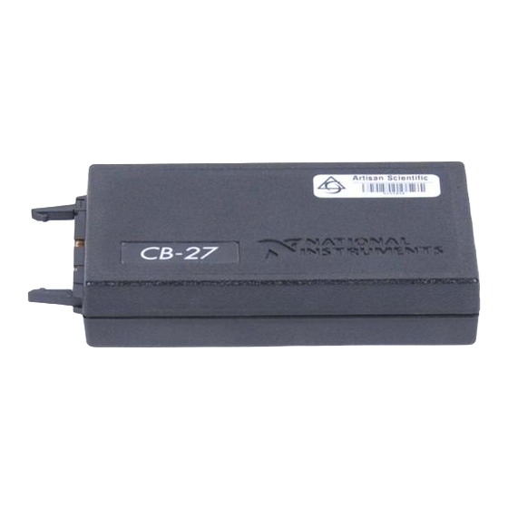
This installation guide describes how to connect the CB-27 connector
block. With the CB-27 connector block, you can easily connect analog and
digital signals to the following National Instruments (NI) 27-pin PCMCIA
data acquisition (DAQ) devices:
•
DAQCard-AO-2DC
•
DAQCard-500
•
DAQCard-516
•
NI PCMCIA-4350
The CB-27 consists of a connector block with 28 screw terminals and a
30-position right angle connector with ejector ears. Each screw terminal
corresponds to a pin number on the 30-position connector. Refer to the
DAQ device user manual for connector pinout information.
The following conventions are used in this guide:
The » symbol leads you through nested menu items and dialog box options
to a final action. The sequence File»Page Setup»Options directs you to
pull down the File menu, select the Page Setup item, and select Options
from the last dialog box.
This icon denotes a note, which alerts you to important information.
This icon denotes a caution, which advises you of precautions to take to
avoid injury, data loss, or a system crash. When this symbol is marked on
the product, refer to the Read Me First: Safety and Radio-Frequency
Interference document, shipped with the product, for precautions to take.
I
NSTALLATION
G
UIDE
October 2002
320933C-01
Advertisement
Table of Contents

Summary of Contents for National Instruments CB-27
- Page 1 • DAQCard-516 • NI PCMCIA-4350 Other NI PCMCIA DAQ devices may be compatible with the CB-27. Refer to the Note device user manual for compatibility information. The CB-27 consists of a connector block with 28 screw terminals and a 30-position right angle connector with ejector ears. Each screw terminal corresponds to a pin number on the 30-position connector.
-
Page 2: What You Need To Get Started
This font is also used for the proper names of disk drives, paths, directories, programs, subprograms, subroutines, device names, functions, operations, variables, filenames and extensions, and code excerpts. What You Need to Get Started To set up and use the CB-27, you need the following components: ❑ A computer ❑... -
Page 3: Installing The Cb-27
Insert the other end of the PR27-30F or PSH32-30F cable into the CB-27 connector. The cable connector is keyed with a centered tab that you must align with the slot on the CB-27 mating header. Firmly push in the cable connector until the ejector ears on the CB-27 connector snap into position. -
Page 4: Connecting The Signals
CB-27. You can fill in the blanks with the signal information from the DAQ device user manual and put the label on the inside of the CB-27 cover for easy reference. The DAQ device kit also contains a completed quick-reference label. - Page 5 CB-27 PCMCIA DAQ Device CB-27 Screw Signal Name Terminal AGND CH0+ CH0– CH1+ CH1– CH2+ CH2– CH3+ CH3– CH4+ CH4– CH5+ CH5– CH6+ CH6– CH7+ CH7– IEX+ IEX– RSVD1 RSVD2 © National Instruments Corporation CB-27 Connector Block Installation Guide...
- Page 6 After you connect the wires to the screw terminals, attach the wires to the CB-27. Bunch the wires from one side of the connector block and tie them to a strain-relief tab using a tie wrap. Repeat for the other side of the connector block.
-
Page 7: Removing The Cable
DAQ device. Remember to push on the latching ears of the PSH32-30F cable before disconnecting it from the NI PCMCIA-4350. Press outward on the ejector ears of the CB-27 connector to pop the cable connector out. © National Instruments Corporation... -
Page 8: Specifications
Maximum working voltage refers to the signal voltage plus the common-mode voltage. Each input must remain within ±20 V of ground. Safety The CB-27 meets the requirements of the following standards for safety and electrical equipment for measurement, control, and laboratory use: • EN 61010-1, IEC 61010-1 •... -
Page 9: Technical Support Resources
Slovenia 3 425 4200, South Africa 11 805 8197, Spain 91 640 0085, Sweden 08 587 895 00, Switzerland 056 200 51 51, Taiwan 02 2528 7227, United Kingdom 01635 523545 © National Instruments Corporation CB-27 Connector Block Installation Guide...


Need help?
Do you have a question about the CB-27 and is the answer not in the manual?
Questions and answers