National Instruments SCB-68 User Manual
68-pin shielded desktop connector block
Hide thumbs
Also See for SCB-68:
- User manual (104 pages) ,
- User manual (64 pages) ,
- Getting started (10 pages)
Advertisement
SCB-68 User Guide
68-Pin Shielded Desktop Connector Block
This guide describes how to connect and use the NI SCB-68 with 68-pin or
100-pin data acquisition (DAQ) devices and other NI products with a 68-pin
SCSI or VHDCI I/O connector. For a complete list of supported devices
and available SCB-68 features, refer to the KnowledgeBase document,
Compatible Devices and Cabling for the NI SCB-68 Terminal Block.
To access this document, go to
.
scb68dev
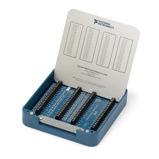
Figure 1 shows the SCB-68 connector block.
8
9
1 Quick Reference Label
2 Top Cover
3 68-Pin Connector
Screws
To use the SCB-68 with devices without analog input
Note
functionality, you must change the default switch setting. Refer to
the
Using the SCB-68 in Direct Feedthrough Mode
information.
ni.com/info
5
10
8
4 Lock Washers
5 Shielding Screws
6 68-Pin I/O Connector
7 Base
Figure 1. SCB-68 Parts Locator Diagram
and enter the info code
1
2
6
7
8 Strain-Relief Screws
9 Strain-Relief Hardware
10 SCB-68 Board
Assembly
3
4
5
section for more
Advertisement
Table of Contents

Related Manuals for National Instruments SCB-68


Summary of Contents for National Instruments SCB-68
- Page 1 SCB-68 User Guide 68-Pin Shielded Desktop Connector Block This guide describes how to connect and use the NI SCB-68 with 68-pin or 100-pin data acquisition (DAQ) devices and other NI products with a 68-pin SCSI or VHDCI I/O connector. For a complete list of supported devices and available SCB-68 features, refer to the KnowledgeBase document, Compatible Devices and Cabling for the NI SCB-68 Terminal Block.
- Page 2 Do not connect hazardous voltages (≥42 V /60 VDC). You can use up to two SCB-68 accessories with AO/M Series devices with two connectors and E Series 100-pin devices. You can use up to four SCB-68 accessories with R Series devices with four connectors, and up to three SCB-68 accessories with R Series devices with three connectors.
- Page 3 8 Temperature Sensor Figure 2. SCB-68 Printed Circuit Board Diagram To get started with the SCB-68, complete the following steps while referring to Figures 1 and 2. If you have not already installed your DAQ device, refer to the DAQ Getting Started Guide for instructions.
- Page 4 /60 VDC can damage the SCB-68, all devices connected to it, and the host computer. 8. Connect the SCB-68(s) to the DAQ device using the appropriate cable(s) for your device. For a complete list of cabling options for supported devices, refer to the KnowledgeBase document, Compatible Devices and Cabling for the NI SCB-68 Terminal Block.
- Page 5 11. Test specific device functionality. Refer to the DAQ Getting Started Guide for detailed information about running test panels in MAX. When you have finished using the SCB-68, power off any external signals connected to the SCB-68 before you power off your computer.
- Page 6 Using the SCB-68 with MIO DAQ Devices You can take measurements with the SCB-68 and multifunction I/O (MIO) DAQ devices, such as E/M/S Series devices, in a number of ways. Switches S1 and S2 provide power to the signal conditioning area of the accessory.
- Page 7 MIO DAQ Device Cable SCB-68 Terminal +5 V Refer to Signal Your Device Conditioning Documentation Temperature for Device AI 0 Sensor Signal Information AI 8 Other Pins Figure 4. MIO DAQ Device Modes Switch Settings © National Instruments Corporation SCB-68 User Guide...
- Page 8 Some DAQ devices provide +5 V power on pin 8 and pin 14. Pin 8 from the DAQ device is protected by an 800 mA, 250 V, 5 · 20 mm fuse on the SCB-68, shown in Figure 2. Shorting pin 8 to ground blows the fuse on the SCB-68.
Need help?
Do you have a question about the SCB-68 and is the answer not in the manual?
Questions and answers