Table of Contents
Advertisement
Quick Links
NATIONAL
INSTRUMENTS
The Software is the Instrument
This guide describes how to connect your data acquisition board and the CB-50 I/O connector
block to your computer.
Introduction
With the CB-50 I/O connector block, you can easily connect analog/digital signals to the
National Instruments data acquisition boards. You can use the CB-50 with the following boards:
PC/XT, PC AT
AT-MIO-16
AT-MIO-16F-5
AT-MIO-16X
AT-AO-6
AT-AO-10
AT-DIO-32F
AT-DIO-24
Lab-PC
Lab-PC+
PC-LPM-16
PC-DIO-24
PC-TIO-10
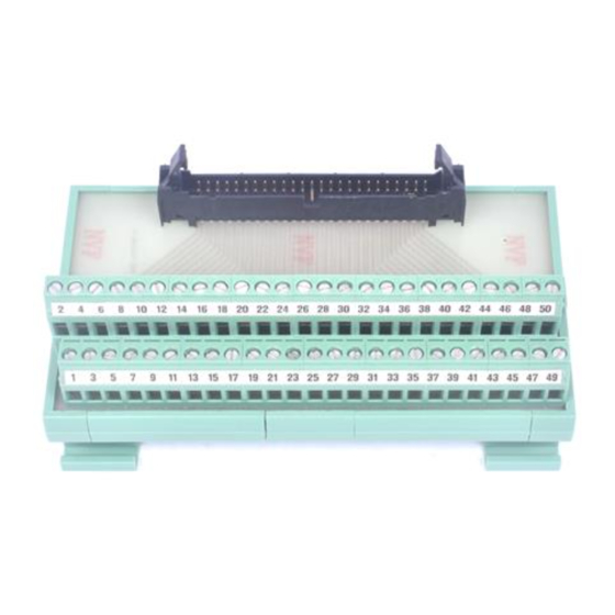
The CB-50 consists of a 0.5 m or 1.0 m ribbon cable and a connector block with 50 screw
terminals. Connector pinout information is in the user manual for each data acquisition board.
At each end, the cable has a keyed connector with a centered tab that you must align with the slot
on the mating header on the connector block or board.
____________________________
Product and company names are trademarks or trade names of their respective companies.
320104-01
© Copyright 1993, 1994 National Instruments Corporation. All rights reserved.
®
®
CB-50 Connector Block
MC-MIO-16
MC-DIO-32F
MC-DIO-24
Installation Guide
PS/2
Macintosh
NB-MIO-16
NB-MIO-16X
NB-DIO-32F
NB-DIO-24
NB-AO-6
NB-TIO-10
Lab-NB
Lab-SE
October 1993
Advertisement
Table of Contents

Related Manuals for National Instruments CB-50


Summary of Contents for National Instruments CB-50
- Page 1 PC-DIO-24 PC-TIO-10 The CB-50 consists of a 0.5 m or 1.0 m ribbon cable and a connector block with 50 screw terminals. Connector pinout information is in the user manual for each data acquisition board. At each end, the cable has a keyed connector with a centered tab that you must align with the slot on the mating header on the connector block or board.
- Page 2 What Your Kit Should Contain The CB-50 I/O connector block kit is available in three versions, depending on your requirements: • CB-50 with 0.5 m cable assembly • CB-50 with 1 m cable assembly • CB-50 without cable assembly In addition, each version of the kit contains the following components: •...
- Page 3 Align Arrows Component Side of Board Align Keying Tab Figure 1. Connecting the 50-Pin Connector to Your Data Acquisition Board 2. Firmly push in the connector for proper contact. 3. Insert the ejector ears into the connector block as shown in Figure 2. Ejector Ears Connector 2 4 6 8 10 12 14 16 18 20 22 24 26 28 30 32 34 36 38 40 42 44 46 48 50...
- Page 4 4. If you plan to mount your connector block for stability, choose one of the following procedures for mounting. If you do not want to mount your connector blocks, proceed to step 5. • For flush mounting, insert the flush-mount brackets into the connector block base as shown in Figure 3.
- Page 5 2 4 6 8 10 12 14 16 18 20 22 24 26 28 30 32 34 36 38 40 42 44 46 48 50 1 3 5 7 9 11 13 15 17 19 21 23 25 27 29 31 33 35 37 39 41 43 45 47 49 Figure 6. Cable Connections to the CB-50...
- Page 6 6. Firmly push in the connector until the ejector ears on the block header connector snap into position. The numbers on the connector block correspond to the pin numbers of the rear panel I/O connector on the board. Removal 1. Press down on the ejector ears of the connector block. The connector will pop out. 2.
Need help?
Do you have a question about the CB-50 and is the answer not in the manual?
Questions and answers