
Related Manuals for National Instruments SCB-68A


Summary of Contents for National Instruments SCB-68A
- Page 1 NI SCB-68A User Manual 68-Pin Shielded Connector Block NI SCB-68A User Manual Français Deutsch ni.com/manuals August 2012 375865A-01...
- Page 2 11500 North Mopac Expressway Austin, Texas 78759-3504 USA Tel: 512 683 0100 For further support information, refer to the Technical Support and Professional Services appendix. To comment on National Instruments documentation, refer to the National Instruments Web site at and enter the Info Code ni.com/info...
- Page 3 Warranty The SCB-68A is warranted against defects in materials and workmanship for a period of one year from the date of shipment, as evidenced by receipts or other documentation. National Instruments will, at its option, repair or replace equipment that proves to be defective during the warranty period.
- Page 4 DEATH, THE USER OR APPLICATION DESIGNER MUST TAKE REASONABLY PRUDENT STEPS TO PROTECT AGAINST SYSTEM FAILURES, INCLUDING BUT NOT LIMITED TO BACK-UP OR SHUT DOWN MECHANISMS. BECAUSE EACH END-USER SYSTEM IS CUSTOMIZED AND DIFFERS FROM NATIONAL INSTRUMENTS' TESTING PLATFORMS AND BECAUSE A USER OR APPLICATION DESIGNER MAY USE NATIONAL...
- Page 5 Conventions The following conventions are used in this manual: <> Angle brackets that contain numbers separated by an ellipsis represent a range of values associated with a bit or signal name—for example, AO <3..0>. » » symbol leads you through nested menu items and dialog box Options»Settings»General options to a final action.
-
Page 6: Table Of Contents
Getting Started with the SCB-68A What You Need to Get Started ..................1-2 Setting up the SCB-68A ....................1-3 Using the SCB-68A in Direct Feedthrough Mode ............1-6 Using the SCB-68A with MIO DAQ Devices..............1-7 Mounting the SCB-68A....................1-9 Panel Mounting...................... - Page 7 Contents Using the Temperature Sensor..................2-16 Taking Thermocouple Measurements ..............2-16 Temperature Sensor Output and Accuracy ............... 2-17 Thermocouple Sources of Error................2-17 Open Thermocouple Detection ................. 2-18 Thermocouple Input Filtering ................... 2-19 Installing Bias Resistors....................2-20 Lowpass Filtering ......................2-21 One-Pole Lowpass RC Filter ..................
- Page 8 NI SCB-68A User Manual Chapter 4 PFI 0 and Digital Input Measurements PFI 0 Channel Pad Configuration..................4-1 Lowpass Filtering ......................4-2 One-Pole Lowpass RC Filter ..................4-5 Selecting Components for Lowpass Filtering ............4-5 Adding Components for Lowpass Digital Filtering on Digital Trigger Input Signals.................
-
Page 9: Getting Started With The Scb-68A
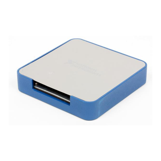
Getting Started with the SCB-68A The SCB-68A, shown in Figure 1-1, is a shielded I/O connector block with 68 screw terminals for easy signal connection to a National Instruments 68-pin or 100-pin DAQ device. Figure 1-1. SCB-68A Parts Locator Diagram... -
Page 10: What You Need To Get Started
You can use up to two SCB-68A accessories with AO/M/X Series devices with two connectors and E Series 100-pin devices. You can use up to four SCB-68A accessories with R Series devices with four connectors, and up to three SCB-68A accessories with R Series devices with three connectors. -
Page 11: Setting Up The Scb-68A
Refer to your device documentation for information about the electrical limits of your device. Install cover prior to use. To avoid electrical shock, do not remove SCB-68A covers unless you are qualified to do so. Before removing the cover, disconnect any live circuit from the connector block. - Page 12 If the kit is missing any of the components in Figure 1-2, contact NI. Note To get started with the SCB-68A, complete the following steps while referring to Figures 1-1 and 1-2. If you have not already installed your DAQ device, refer to the installation guide that came with your DAQ device for instructions.
- Page 13 Remove the film from both sides of the cover. (Optional) If you are not using the SCB-68A with Connector 0 of an M/X Series device, attach the quick reference label to the inside of the cover as shown in Figure 1-1. For quick reference label PDFs for most compatible devices, refer to the KnowledgeBase document, Where Can I Find NI SCB-68A Quick Reference Labels?.
-
Page 14: Using The Scb-68A In Direct Feedthrough Mode
Chapter 1 Getting Started with the SCB-68A 10. Connect the SCB-68A(s) to the DAQ device using the appropriate cable(s) for your device. For a complete list of cabling options for supported devices, refer to the KnowledgeBase document, Compatible Devices and Cabling for the NI SCB-68/SCB-68A Terminal Block. -
Page 15: Using The Scb-68A With Mio Daq Devices
You can take measurements with the SCB-68A and multifunction I/O (MIO) DAQ devices, such as E/M/S/X Series devices, in a number of ways. The SCB-68A has a temperature sensor for cold-junction compensation (CJC) to accommodate thermocouples; switches S1.1 and S1.2 configure the temperature sensor for different analog input settings. - Page 16 Chapter 1 Getting Started with the SCB-68A Table 1-2. MIO DAQ Device Switch Settings Switch Setting Description MIO with disabled temperature sensor mode (default configuration) —Move switches S1.1, S1.2, S2.1, S2.2, and S2.3 to the positions shown at left. In this mode: •...
-
Page 17: Mounting The Scb-68A
Measurements. Mounting the SCB-68A You can use the SCB-68A on a desktop, or mount it to a panel or a standard DIN rail. Panel Mounting Three keyholes are located on the back of the SCB-68A for mounting it to a panel or wall. To mount the SCB-68A to a board or panel, complete the following steps. -
Page 18: Din Rail Mounting
The NI 9913 DIN rail mounting kit (part number 781740-01) contains one clip for mounting the SCB-68A on a standard 35 mm DIN rail. Fasten the DIN rail clip to the accessory using two FLH #6-32 × 5/16” screws (included in the kit) with a #2 Phillips screwdriver, as shown in Figure 1-5. -
Page 19: Securing The Cover On The Scb-68A
Securing the Cover on the SCB-68A In most cases, attaching the cover with the integrated magnets is sufficient. To permanently secure the cover to the SCB-68A base, you will need two M3 × 6 (4-40 × 5/16) thread-forming ... -
Page 20: Soldering And Desoldering Guidelines
As you solder and desolder components on the SCB-68A, refer to Figure 1-2. The SCB-68A ships with surface mount 0 Ω resistors in the F and G positions. You must remove the resistors to use the positions. Use a low-wattage soldering iron (20 to 30 W) when soldering to the SCB-68A. -
Page 21: Related Documentation
NI SCB-68A User Manual Related Documentation For more information about using the SCB-68A with your DAQ device, refer to the following resources: • Documentation for your DAQ device at ni.com/manuals • Measurement & Automation Explorer Help • NI-DAQmx Help •... -
Page 22: Analog Input And Temperature Sensor Measurements
This chapter also describes how to condition signals by adding components to the open component locations of the SCB-68A for lowpass and highpass filtering, current input measurement, and attenuating voltage applications, as well as installing bias resistors. -
Page 23: Analog Input Circuitry And Channel Pad Configuration
Analog Input Circuitry and Channel Pad Configuration When you use the SCB-68A with a 68-pin or 100-pin MIO DAQ device, you can use the component pads on the SCB-68A to condition 16 AI channels. Figure 2-1 shows the analog input and CJC circuitry on the SCB-68A. - Page 24 NI SCB-68A User Manual Figure 2-2 illustrates the basic AI channel configuration. You can use AI <i> and AI <i+8> as either a differential channel pair or as two single-ended channels. Figure 2-2. Analog Input Channel Circuitry for AI <i> and AI <i+8>...
- Page 25 Chapter 2 Analog Input and Temperature Sensor Measurements To use the SCB-68A with ground-referenced single-ended inputs, do not use the open positions that connect the input to AI GND, positions B and D, for grounded sources as shown in Figure 2-3. Build any signal conditioning circuitry requiring a ground reference in the custom breadboard area using AI SENSE as the ground reference instead of building the circuitry in the open component positions.
-
Page 26: Connecting Analog Input Signals
NI SCB-68A User Manual Table 2-1 correlates the component labels of the SCB-68A to component locations A through G for analog input signals. Table 2-1. Analog Input Channels Component Locations Channel † † Single-Ended Differential Positions A, B , C, D... - Page 27 Chapter 2 Analog Input and Temperature Sensor Measurements Table 2-2. Analog Input Configuration Floating Signal Sources (Not Connected to Ground-Referenced Building Ground) Signal Sources Examples: Example: • Ungrounded thermocouples • Plug-in instruments with non-isolated outputs • Signal conditioning with AI Ground- isolated outputs Reference •...
-
Page 28: Floating Signal Sources
NI SCB-68A User Manual Floating Signal Sources A floating signal source is not connected to the building ground system, but has an isolated ground-reference point. Some examples of floating signal sources are outputs of transformers, thermocouples, battery-powered devices, optical isolators, and isolation amplifiers. An instrument or device that has an isolated output is a floating signal source. -
Page 29: When To Use Referenced Single-Ended (Rse) Connections With Floating Signal Sources
Chapter 2 Analog Input and Temperature Sensor Measurements When to Use Referenced Single-Ended (RSE) Connections with Floating Signal Sources Only use RSE input connections if the input signal meets the following conditions: • The input signal can share a common reference point, AI GND, with other signals that use RSE. - Page 30 NI SCB-68A User Manual However, for larger source impedances, this connection leaves the differential signal path significantly off balance. Noise that couples electrostatically onto the positive line does not couple onto the negative line because it is connected to ground. This noise appears as a differential mode signal instead of a common-mode signal, and thus appears in your data.
- Page 31 Chapter 2 Analog Input and Temperature Sensor Measurements Figure 2-6. Floating Signal Source Differential Connections with Balanced Bias Resistors Bias Resistors (see text) Floating Instrumentation Signal Amplifier Source – PGIA AI– Measured – Voltage – Bias Current Return Paths Input Multiplexers AI SENSE AI GND I/O Connector...
-
Page 32: Using Non-Referenced Single-Ended (Nrse) Connections For Floating Signal Sources
NI SCB-68A User Manual Figure 2-7. AC-Coupled Floating Source Differential Connections with Balanced Bias Resistors DAQ Device AC Coupling AC Coupled Floating Signal – Source AI– AI SENSE AI GND Refer to the Installing Bias Resistors section for information about installing bias resistors on the SCB-68A. -
Page 33: Using Referenced Single-Ended (Rse) Connections For Floating Signal Sources
Chapter 2 Analog Input and Temperature Sensor Measurements Using Referenced Single-Ended (RSE) Connections for Floating Signal Sources Figure 2-9 shows how to connect a floating signal source to the DAQ device configured for RSE mode. Figure 2-9. RSE Connections for Floating Signal Sources AI <0..16>... -
Page 34: When To Use Non-Referenced Single-Ended (Nrse) Connections With Ground-Referenced Signal Sources
NI SCB-68A User Manual DIFF signal connections reduce noise pickup and increase common-mode noise rejection. DIFF signal connections also allow input signals to float within the common-mode limits of the NI-PGIA. Refer to the Using Differential Connections for Ground-Referenced Signal Sources section for more information about differential connections. -
Page 35: Using Differential Connections For Ground-Referenced Signal Sources
Chapter 2 Analog Input and Temperature Sensor Measurements Using Differential Connections for Ground-Referenced Signal Sources Figure 2-10 shows how to connect a ground-referenced signal source to the DAQ device configured in differential mode. Figure 2-10. Differential Connections for Ground-Referenced Signal Sources AI + Ground- Referenced... -
Page 36: Using Non-Referenced Single-Ended (Nrse) Connections For Ground-Referenced Signal Sources
NI SCB-68A User Manual Using Non-Referenced Single-Ended (NRSE) Connections for Ground-Referenced Signal Sources Figure 2-11 shows how to connect ground-reference signal sources in NRSE mode. Figure 2-11. Single-Ended Connections for Ground-Referenced Signal Sources (NRSE Configuration) I/O Connector AI <0..16> Ground-... -
Page 37: Using The Temperature Sensor
CJC with the SCB-68A is accurate only if the temperature sensor reading is close to the actual temperature of the screw terminals. Therefore, when reading thermocouples, keep the SCB-68A away from drafts or other temperature gradients, such as those caused by heaters, radiators, fans, and warm equipment. -
Page 38: Temperature Sensor Output And Accuracy
Compensation error—Can arise from two sources—inaccuracy of the temperature sensor and temperature differences between the temperature sensor and the screw terminals. The temperature sensor on the SCB-68A is specified to be accurate to ±1 °C. You can minimize temperature differences between the temperature sensor and the screw terminals by keeping the SCB-68A away from drafts, heaters, and warm equipment. -
Page 39: Open Thermocouple Detection
+5 V. A resistor of a few MΩ or more is sufficient, but a high-value resistor allows you to detect an open or defective thermocouple. Refer to the Soldering and Desoldering Components on the SCB-68A section Note... -
Page 40: Thermocouple Input Filtering
NI SCB-68A User Manual • Single-ended analog input open thermocouple detection—Use position A for one channel and C for the next channel when you connect a high-value resistor between the positive input and +5 V. Leave the 0 Ω resistors at positions F and G in place for each channel used. -
Page 41: Installing Bias Resistors
To install a single bias resistor on the negative line (AI–) of a differential pair, put the resistor in position D on the SCB-68A, as shown in Figure 2-14. Leave the 0 Ω resistors at positions F and G in place for each channel used. -
Page 42: Lowpass Filtering
NI SCB-68A User Manual Figure 2-15. AI Differential Configuration with Balanced Bias Resistors + 5 V AI GND AI i – AIi+8 AI i + 8 + 5 V AI GND Lowpass Filtering Lowpass filters highly or completely attenuate signals with frequencies above the cut-off frequency, or high-frequency stopband signals. - Page 43 Chapter 2 Analog Input and Temperature Sensor Measurements Figures 2-16 and 2-17 show the Bode Plots for the ideal filter and the real filter, respectively, and indicate the attenuation of each transfer function. Figure 2-16. Transfer Function Attenuation for an Ideal Filter Passband Stopband Log Frequency...
- Page 44 NI SCB-68A User Manual Figure 2-18. Square Wave Input Signal Time (t) Figures 2-19 and 2-20 show the difference in response to a square wave between an ideal and a real filter, respectively. Figure 2-19. Response of an Ideal Filter to a Square Wave Input Signal Time (t) Figure 2-20.
-
Page 45: One-Pole Lowpass Rc Filter
Chapter 2 Analog Input and Temperature Sensor Measurements One-Pole Lowpass RC Filter Figure 2-21 shows the transfer function of a simple series circuit consisting of a resistor (R) and capacitor (C) when the voltage across R is assumed to be the output voltage (V Figure 2-21. -
Page 46: Adding Components For Lowpass Filters On Analog Input Signals
Add the capacitor to position B or D, depending on the AI channel you are using. Refer to Table 2-1 for component positions for all analog input channels. The SCB-68A ships with a surface mount 0 Ω resistors in the F and G positions. You must remove the resistor to use the position. -
Page 47: Analog Input Lowpass Filtering Applications
Adding RC filters to scanning channels greatly reduces the practical scanning rate, since the instrumentation amplifier settling time can be increased to 10T or longer, where T = (R)(C). Figure 2-23. SCB-68A Circuit Diagram for Single-Ended Analog Input Lowpass Filter on AI <i> + 5 V... -
Page 48: Highpass Filtering
Some devices, such as the Note (NI 6115/6120/6289 Devices Only) NI 6115/6120/6289, provide filters and may not need antialiasing filters implemented at the SCB-68A terminal block. Refer to your device documentation for more information. Highpass Filtering Highpass filters highly or completely attenuate signals with frequencies below the cut-off frequency, or low-frequency stopband signals. - Page 49 Chapter 2 Analog Input and Temperature Sensor Measurements In practice, highpass filters subject input signals to a mathematical transfer function that approximates the characteristics of an ideal filter. By analyzing the Bode Plot, or the plot that represents the transfer function, you can determine the filter characteristics. Figures 2-25 and 2-26 show the Bode Plots for the ideal filter and the real filter, respectively, and indicate the attenuation of each transfer function.
-
Page 50: One-Pole Highpass Rc Filter
NI SCB-68A User Manual One-Pole Highpass RC Filter Figure 2-27 shows the transfer function of a simple series circuit consisting of a resistor (R) and capacitor (C) when the voltage across R is assumed to be the output voltage (V Figure 2-27. -
Page 51: Adding Components For Highpass Filtering On Analog Input Signals
Add the capacitor to position F or G, depending on the AI channel you are using. Refer to Table 2-1 for component positions for all analog input channels. The SCB-68A ships with a surface mount 0 Ω resistor in the F and G positions. You must remove the resistor to use the position. -
Page 52: Analog Input Highpass Filtering Applications
NI SCB-68A User Manual Figure 2-29. SCB-68A Circuit Diagram for Single-Ended Analog Input Highpass Filter on AI <i> + 5 V AI GND AI i AIi+8 AI i + 8 + 5 V AI GND Analog Input Highpass Filtering Applications One of the most common applications for highpass filters for analog inputs is to use the filter to do AC coupling. -
Page 53: Current Input Measurement
Chapter 2 Analog Input and Temperature Sensor Measurements Without the AC coupling you would use the ±10 V range or the 0–10 V range. After passing through the filter, the dynamic portion of the signal is retained and centered around 0, as shown in Figure 2-31. -
Page 54: Selecting A Resistor For Current Input Measurement
Differential analog inputs—To build a one-resistor circuit that measures current at the differential inputs of the SCB-68A, add the resistor to position E for each differential channel pair that is used. Leave the 0 Ω resistors in place for positions F and G. Refer to Table 2-1 for component positions for all analog input channels. - Page 55 Single-ended analog inputs—To build a one-resistor circuit that measures current at the single-ended analog inputs of the SCB-68A, add the resistor to position B or D, depending on the channel being used. Leave the 0 Ω resistors in place for channel positions F and G, respectively.
-
Page 56: Attenuating Voltage
NI SCB-68A User Manual Figure 2-34. Measuring Current with Single-Ended Analog Input (AI <i>) + 5 V AI GND AI i AIi+8 AI i + 8 + 5 V AI GND Attenuating Voltage Transducers can generate more than 10 VDC per channel, but DAQ devices cannot read more than 10 VDC per input channel. -
Page 57: Selecting Components For Attenuating Voltage
DAQ device. Input voltages >30 V /42 V /60 VDC can damage the SCB-68A, any devices connected to it, and the host computer. Overvoltage can also cause an electric shock hazard for the operator. Selecting Components for Attenuating Voltage To set up the resistors, complete the following steps. -
Page 58: Adding Components For Attenuating Voltage On Analog Input Signals
SCB-68A, refer to Figure 2-36. Refer to Table 2-1 for component positions for all analog input channels. The SCB-68A ships with a surface mount 0 Ω resistor in the F and G positions. You must remove the resistors to use these positions. -
Page 59: Analog Input Voltage Dividers
+ 5 V AI GND Install resistors in positions B and F, or positions D and G, depending on the channel you are using on the SCB-68A. Use the following equation to calculate the gain of the circuit: B orD ------------------------------------------ -... - Page 60 NI SCB-68A User Manual × Input Impedance --------------------------------------------------------- - Input Impedance is the new input impedance. Refer to the device specifications for the input impedance of your device. © National Instruments | 2-39...
-
Page 61: Analog Output Waveforms
Analog Output Channel Pad Configuration When you use the SCB-68A with a 68-pin or 100-pin MIO DAQ device, you can use the component pads on the SCB-68A to condition two AO channels. Figure 3-1 shows the circuitry for both analog output channels on the SCB-68A. -
Page 62: Lowpass Filtering
Figure 3-2. Analog Output Channel Pad Configuration AO GND AO 0 AO 1 AO GND Table 3-1 correlates the component labels of the SCB-68A to component locations A and B for analog output channels 0 and 1. Table 3-1. Analog Output Channels Component Locations † Channel... - Page 63 NI SCB-68A User Manual filters have a phase shift that is linear with respect to frequency. This linear phase shift delays signal components of all frequencies by a constant time, independent of frequency, thereby preserving the overall shape of the signal.
- Page 64 Chapter 3 Analog Output Waveforms of the signal. For example, when the square wave, shown in Figure 3-5, enters a filter, an ideal filter smooths the edges of the input, whereas a real filter causes some ringing in the signal as the higher frequency components of the signal are delayed.
-
Page 65: One-Pole Lowpass Rc Filter
NI SCB-68A User Manual Figure 3-7. Response of a Real Filter to a Square Wave Input Signal Time (t) One-Pole Lowpass RC Filter Figure 3-8 shows the transfer function of a simple series circuit consisting of a resistor (R) and capacitor (C) when the voltage across R is assumed to be the output voltage (V Figure 3-8. -
Page 66: Selecting Components For Lowpass Filtering
B, as shown in Figure 3-9. The SCB-68A ships with a surface mount 0 Ω resistor in the A position. You must remove the resistor to use the position. Refer to Table 3-1 for component positions for both analog output channels. -
Page 67: Analog Output Lowpass Filtering Applications
NI SCB-68A User Manual Figure 3-9. SCB-68A Circuit Diagram for Analog Output Lowpass Filter AO GND AO 0 Analog Output Lowpass Filtering Applications The following applications benefit from lowpass filtering: • Protection for external circuitry—Lowpass filters can smooth stairstep-like curves on AO signals. -
Page 68: Attenuating Voltage
DAQ device. Input voltages >30 V /42 V /60 VDC can damage the SCB-68A, any devices connected to it, and the host computer. Overvoltage can also cause an electric shock hazard for the operator. 3-8 | ni.com... -
Page 69: Selecting Components For Attenuating Voltage
To build a two-resistor circuit for attenuating voltages at the AO 0 and AO 1 pins on the SCB-68A, refer to the pad positions in Figure 3-12. The SCB-68A ships with a surface mount 0 Ω resistor in the A position. You must remove the resistor to use the position. Refer to Table 3-1 for component positions for both analog output channels. -
Page 70: Analog Output Voltage Dividers
Chapter 3 Analog Output Waveforms Install resistors in positions A and B and determine the gain according to Equation 3-5: (3-5) ----------------------- - Analog Output Voltage Dividers When you use the circuit shown in Figure 3-11 for analog output, the output impedance changes. Thus, you must choose the values for R and R so that the final output impedance value is as... -
Page 71: Pfi 0 And Digital Input Measurements
PFI 0 Channel Pad Configuration When you use the SCB-68A with a 68-pin or 100-pin MIO DAQ device, you can use the SC10 component pads on the SCB-68A to condition PFI 0. Figure 4-1 shows the digital trigger circuitry for PFI 0. -
Page 72: Lowpass Filtering
PFI 0 D GND The SCB-68A ships with a surface mount 0 Ω resistor in the A position. You must remove the resistor to use the position. If you remove your custom components from the A position, you must reinstall a 0 Ω resistor. The B position contains through hole pads that can be used for two components to be connected in parallel. - Page 73 NI SCB-68A User Manual Figure 4-3. Transfer Function Attenuation for an Ideal Filter Passband Stopband Log Frequency Figure 4-4. Transfer Function Attenuation for a Real Filter Passband Stopband Transition Region Log Frequency The cut-off frequency, f , is defined as the frequency beyond which the gain drops 3 dB.
- Page 74 Chapter 4 PFI 0 and Digital Input Measurements Figure 4-5. Square Wave Input Signal Time (t) Figures 4-6 and 4-7 show the difference in response to a square wave between an ideal and a real filter, respectively. Figure 4-6. Response of an Ideal Filter to a Square Wave Input Signal Time (t) Figure 4-7.
-
Page 75: One-Pole Lowpass Rc Filter
NI SCB-68A User Manual One-Pole Lowpass RC Filter Figure 4-8 shows the transfer function of a simple series circuit consisting of a resistor (R) and capacitor (C) when the voltage across R is assumed to be the output voltage (V Figure 4-8. -
Page 76: Adding Components For Lowpass Digital Filtering On Digital Trigger Input Signals
For PFI 0, add the resistor to position A and the capacitor to position B. Refer to Figure 4-9 for the digital input channel pad configuration. The SCB-68A ships with a surface mount 0 Ω resistor in the A position. You must remove the resistor to use the position. -
Page 77: Pfi 0 Lowpass Filtering Applications
NI SCB-68A User Manual PFI 0 Lowpass Filtering Applications Lowpass filters can function as debouncing filters to smooth noise on digital trigger input signals, thus enabling the trigger-detection circuitry of the DAQ device to understand the signal as a valid digital trigger. -
Page 78: Attenuating Voltage
DAQ device. Input voltages >30 V /42 V /60 VDC can damage the SCB-68A, any devices connected to it, and the host computer. Overvoltage can also cause an electric shock hazard for the operator. 4-8 | ni.com... -
Page 79: Selecting Components For Attenuating Voltage
Adding Components for Attenuating Voltage on Digital Inputs To build a two-resistor circuit for attenuating voltages at the PFI 0 pin on the SCB-68A, refer to the pad positions in Figure 4-13. The SCB-68A ships with a surface mount 0 Ω resistor in the SC10 position. You must remove the resistor to use the position. -
Page 80: Digital Input Voltage Dividers
Chapter 4 PFI 0 and Digital Input Measurements Figure 4-13. SCB-68A Circuit Diagram for Digital Input Attenuation SC10 PFI 0 D GND Use positions A and B for PFI 0, and determine the gain according to Equation 4-5: (4-5) ----------------- -... -
Page 81: Fuse And Power Information
1 A self-resetting fuse, shown in Figure 1-2, SCB-68A Printed Circuit Board Diagram. Shorting pin 8 to ground trips the fuse on the SCB-68A. Pin 14 is not fuse-protected on the SCB-68A. Shorting pin 14 will cause the fuse on the DAQ device to open. -
Page 82: Adding Power Filters
A 470 Ω series resistor (R21) is part of the power filter for the +5 V power on the SCB-68A. Due to the nature of the filter design, as the filtered +5 V is loaded, the voltage supplied to the SCB-68A circuitry and screw terminal 8 decreases. -
Page 83: Appendix A Specifications
Specifications This appendix lists the SCB-68A specifications. These specifications are typical at 25 °C unless otherwise noted. Do not connect hazardous voltages (>30 V /42 V /60 VDC) to the Caution SCB-68A. Temperature Sensor Accuracy............±1.0 °C over a 0 to 70 °C range Power Requirement Power consumption (at +5 VDC, ±5%) - Page 84 Appendix A Specifications Safety Voltages Connect only voltages that are no greater than 30 V /42 V /60 VDC. Environmental Temperature Operating ..........0 to 70 °C Storage ............–20 to 70 °C Relative humidity Operating ..........5 to 90% RH, noncondensing Storage ............5 to 90% RH, noncondensing Pollution Degree ..........2 Maximum altitude..........2,000 m Indoor use only.
- Page 85 At the end of the product life cycle, all products must be sent to EU Customers a WEEE recycling center. For more information about WEEE recycling centers, National Instruments WEEE initiatives, and compliance with WEEE Directive 2002/96/EC on Waste and Electronic Equipment, visit ni.com/environment/...
- Page 86 You can also register for instructor-led, hands-on courses at locations around the world. • System Integration—If you have time constraints, limited in-house technical resources, or other project challenges, National Instruments Alliance Partner members can help. To learn more, call your local NI office or visit ni.com/alliance •...
- Page 87 Appendix B Technical Support and Professional Services You also can visit the Worldwide Offices section of to access the branch ni.com/niglobal office Web sites, which provide up-to-date contact information, support phone numbers, email addresses, and current events. B-2 | ni.com...
- Page 88 (figure) differential 2-18 cold-junction compensation (figure) single-ended 2-19 digital inputs (figure) thermocouple input filtering 2-19 digital trigger (figure) voltage dividers 2-38 PFI 0 (figure) cold-junction compensation (CJC) circuit diagram (figure) © National Instruments | I-1...
- Page 89 Index components using with ground-referenced signal adding sources 2-14 attenuating voltage 2-37 when to use with floating signal current input measurement 2-33 sources highpass filtering 2-30 when to use with ground-referenced lowpass filtering 2-25 signal sources 2-12 locations digital inputs analog input (table) attenuating voltage analog output (table)
- Page 90 NI SCB-68A User Manual components adding for analog input 2-25 ground-referenced signal sources adding for analog output connecting 2-12 adding for digital filtering description 2-12 selecting 2-24 using in differential mode 2-14 one-pole lowpass RC filter 2-24 using in NRSE mode...
- Page 91 Index power filters printed circuit board diagram (figure) technical support programming examples (NI resources) temperature sensor accuracy 2-17 output 2-17 thermocouples 2-21 referenced single-ended connections input filtering 2-19 using with floating signal sources 2-12 open thermocouple detection 2-18 when to use with floating signal differential analog input 2-18 sources...
Need help?
Do you have a question about the SCB-68A and is the answer not in the manual?
Questions and answers