Advertisement
Table of Contents
- 1 Table of Contents
- 2 What You Need to Get Started
- 3 Installing the BNC-2120
- 4 Connecting Analog Input Signals
- 5 Connecting Analog Output Signals
- 6 Using the Function Generator
- 7 Connecting Timing I/O Signals
- 8 Connecting User-Defined Signals
- 9 Connecting Digital I/O Signals
- 10 Specifications
- Download this manual
INSTALLATION GUIDE
BNC-2120
Connector Accessory for E/M/S/X Series Devices
This installation guide describes how to install, configure, and use your BNC-2120 accessory
with 68-pin or 100-pin E/M/S/X Series multifunction data acquisition (DAQ) devices. This
document also contains accessory specifications.
The BNC-2120 has the following features:
•
Eight BNC connectors for analog input (AI) connection
•
Onboard temperature reference
•
Thermocouple connector
•
Resistor measurement screw terminals
•
Two BNC connectors for analog output (AO) connection
•
Screw terminals for digital I/O (DIO) connection with state indicators
•
Screw terminals for timing I/O (TIO) connection
•
Two user-defined BNC connectors
•
A function generator with the following outputs:
-
Frequency-adjustable, TTL-compatible square wave
-
Frequency- and amplitude-adjustable sine wave or triangle wave
•
Quadrature encoder
•
A 68-pin I/O connector that connects to multifunction DAQ devices
•
Can be used on a desktop or mounted on a DIN rail
Contents
What You Need to Get Started ................................................................................................. 2
Installing the BNC-2120........................................................................................................... 2
Connecting Analog Input Signals............................................................................................. 5
Connecting Differential Analog Input Signals ................................................................. 6
Measuring Floating Signals ...................................................................................... 6
Measuring Ground-Referenced Signals.................................................................... 7
Measuring Temperature.................................................................................................... 7
Measuring Resistance ....................................................................................................... 8
Connecting Analog Output Signals .......................................................................................... 8
Using the Function Generator................................................................................................... 9
Connecting Timing I/O Signals................................................................................................ 9
Using the Quadrature Encoder ......................................................................................... 12
Connecting User-Defined Signals ............................................................................................ 13
Connecting Digital I/O Signals................................................................................................. 14
Specifications............................................................................................................................ 14
Advertisement
Table of Contents

Related Manuals for National Instruments BNC-2120


Summary of Contents for National Instruments BNC-2120
-
Page 1: Table Of Contents
INSTALLATION GUIDE BNC-2120 Connector Accessory for E/M/S/X Series Devices This installation guide describes how to install, configure, and use your BNC-2120 accessory with 68-pin or 100-pin E/M/S/X Series multifunction data acquisition (DAQ) devices. This document also contains accessory specifications. The BNC-2120 has the following features: •... -
Page 2: What You Need To Get Started
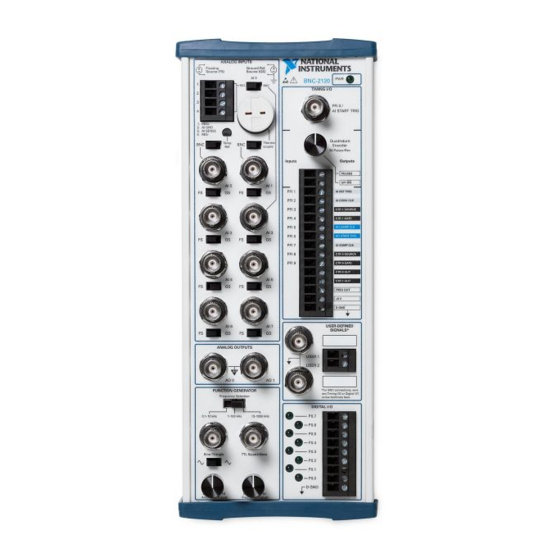
Figure 1 shows the front panel of the BNC-2120. You can use two BNC-2120 accessories with both connectors of two connector M/X Series devices. You cannot use the BNC-2120 with Connector 1 of NI 6225/6255 devices. 2 | ni.com | BNC-2120 Installation Guide... - Page 3 Switch (AI 1) Switch 23 Timing I/O BNC Connector Analog Input BNC 14 Frequency Adjust Knob 24 Power Indicator LED Connectors 15 Amplitude Adjust Knob FS/GS Switches 16 Digital I/O Screw Terminals BNC-2120 Installation Guide | © National Instruments | 3...
- Page 4 BNC-2120, the DAQ device, or the host computer. National Instruments is not liable for damage resulting from these connections. Place the BNC-2120 near the host computer or PXI/PXI Express chassis or use the optional DIN Rail Mounting kit for UMI-FLEX-6 and BNC boxes (Part Number 777972-01), which you can order from National Instruments at ni.com...
-
Page 5: Connecting Analog Input Signals
Refer to the DAQ Getting Started guides for detailed information about running test panels in MAX. When you have finished using the BNC-2120, power off any external signals connected to the BNC-2120 before you power off your computer. -
Page 6: Connecting Differential Analog Input Signals
AI GND 4.99 kΩ When using the BNC-2120 with Connector 1 of two connector M/X Series devices, the AI <0..7> BNCs on the BNC-2120 map to the AI <16..23> channels on the device. 6 | ni.com | BNC-2120 Installation Guide... -
Page 7: Measuring Ground-Referenced Signals
°C = Volts × 100 The sensor is accurate to ±1.5 °C. To use the thermocouple on the BNC-2120, move the BNC/Thermocouple switch above the AI 1 BNC to Thermocouple. You can connect any type of thermocouple with a two-prong miniature or subminiature male connector to the thermocouple connector. -
Page 8: Measuring Resistance
Refer to your DAQ device documentation for information about the use of these signals. When using the BNC-2120 with Connector 1 of two connector M/X Series devices, the AO <0..1> BNCs on the BNC-2120 map to the AO <2..3> channels on the device. -
Page 9: Using The Function Generator
Connect the timing I/O signals of your DAQ device to the PFI 0/P1.0 (AI START TRIG) BNC or the timing I/O screw terminals on the BNC-2120. When connecting signals to the screw terminals, use 28–16 AWG wire with the insulation stripped to 0.28 in. - Page 10 Table 2. BNC-2120 Timing I/O BNC/Terminal Descriptions (Continued) BNC/Terminal Description PFI 2/P1.2 Programmable Function Interface channel 2 or Port 1 Digital Input/Output channel 2 AI CONV CLK (AI Convert Clock Signal)—As an output, this pin is the ai/ConvertClock signal. A high-to-low edge on AI CONV indicates that an A/D conversion is occurring.
- Page 11 The current available depends on the product to which it is connected. D GND Digital Ground—This terminal supplies the reference for the digital signals at the I/O connector as well as the +5 VDC supply. BNC-2120 Installation Guide | © National Instruments | 11...
-
Page 12: Using The Quadrature Encoder
Using the Quadrature Encoder The BNC-2120 contains a mechanical quadrature encoder circuit that produces 96 pulses per encoder revolution. Two outputs, PULSES and UP/DN, are at the screw terminals located below the quadrature encoder knob. PULSES outputs a pulse train generated by rotating the encoder shaft. It provides four pulses per one mechanical click of the encoder. -
Page 13: Connecting User-Defined Signals
I/O signal of your choice. The USER 1 and USER 2 BNC connectors are routed (internal to the BNC-2120) to the USER 1 and USER 2 screw terminals, as shown in Figure 5. Figure 5. USER <1..2> BNC Connections... -
Page 14: Connecting Digital I/O Signals
Connect to the digital I/O signals of your DAQ device to the digital I/O screw terminals, P0.<0..7>, on the BNC-2120. You can individually configure each signal as an input or output. D GND is available at the screw terminals to supply the reference for the DIO signals. When connecting signals to the screw terminals, use 28–16 AWG wire with the insulation stripped to... - Page 15 Frequency adjust........Through the Frequency Adjust knob Amplitude range ........200 mV to 4.8 V Amplitude adjust........Through the Amplitude Adjust knob Output impedance........453 Ω (sine/triangle wave) 50 Ω (square wave) BNC-2120 Installation Guide | © National Instruments | 15...
- Page 16 Power available at +5 V screw terminal ...Multifunction DAQ device power, less power consumed at +5 VDC (±5%) Physical Dimensions ............26.7 cm × 11.2 cm × 5.97 cm (10.5 in. × 4.41 in. × 2.35 in.) Weight ...............1,040 g (2 lb 4.7 oz) 16 | ni.com | BNC-2120 Installation Guide...
- Page 17 Online Note Product Certification section. The protection provided by the BNC-2120 can be impaired if it is used in Caution a manner not described in this document. Electromagnetic Compatibility This product meets the requirements of the following EMC standards for electrical equipment for measurement, control, and laboratory use: •...
- Page 18 At the end of the product life cycle, all products must be sent to EU Customers a WEEE recycling center. For more information about WEEE recycling centers, National Instruments WEEE initiatives, and compliance with WEEE Directive 2002/96/EC on Waste and Electronic Equipment, visit ni.com/environment/...
- Page 19 Instruments Patents Notice at ni.com/patents. Refer to the Export Compliance Information at ni.com/legal/export-compliance for the National Instruments global trade compliance policy and how to obtain relevant HTS codes, ECCNs, and other import/export data. © 1999–2012 National Instruments. All rights reserved.
Need help?
Do you have a question about the BNC-2120 and is the answer not in the manual?
Questions and answers