HiTi Digital CS-200e Disassembly And Assembly
Hide thumbs
Also See for CS-200e:
- User manual (113 pages) ,
- Service manual (84 pages) ,
- User manual (79 pages)

Related Manuals for HiTi Digital CS-200e


Summary of Contents for HiTi Digital CS-200e
- Page 1 Confidential Disassembly & Assembly Guide CS-200e Version: 1.0 The Disassembly & Assembly Guide is written mainly for engineers. Do not reproduce or duplicate.
- Page 2 Confidential Revision History Date Revision Description Remark 2011/6 V1.0 The first release...
-
Page 3: Table Of Contents
Confidential Index Chapter 1. Disassembly & Assembly ....................4 1. Safety Instructions........................4 2. Tools............................5 3. Do not disassemble These Parts ................... 6 4. Disassembly ..........................7 4-1 Case of card printer & chassis ..................7 4-2 Main Board ........................14 4-3 Flipper Module ....................... -
Page 4: Chapter 1. Disassembly & Assembly
Confidential Chapter 1. Disassembly & Assembly 1. Safety Instructions • Read these instructions carefully. Save these instructions for future reference. • Follow all warnings and instructions marked on the printer. • Unplug the printer from the wall outlet before disassembly. •... -
Page 5: Tools
Confidential 2. Tools Tweezers Wire Cutter Screwdriver– minus Screwdriver– plus... -
Page 6: Do Not Disassemble These Parts
Confidential 3. Do not disassemble These Parts HiTi strictly prohibits anyone to disassemble the TPH (Thermal Print Head) and the Platen Motor. Both parts need to be calibrated by a specific calibration device and cannot be repaired on site. Fixing screws (DO NOT disassemble) Located on the both sides of the TPH module Fixing screws of Platen Motor (Must disassemble with care &... -
Page 7: Disassembly
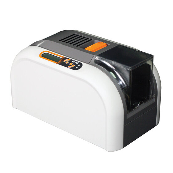
Confidential 4. Disassembly 4-1 Case of card printer & chassis Maintenance Parts Replacement Procedures Parts Name Parts No. The case of card printer & chassis Tools Screwdriver Procedure No. Appearance view of CS-200e... - Page 8 Confidential Unscrew 4 screws that hold the upper cover (marked in red circles in the figure below) (PS_ID_DOOR_F_RAPID_C1 56.C0104.012) Slide down the upper cover to take it off...
- Page 9 Confidential Unscrew the corresponding screws which have been marked in circles of different colors for the part that you are going to take off Front (case front & ADF cover) Pink Back Brown Left Green Right Blue...
- Page 10 Confidential...
- Page 11 Confidential The rest of 2 screws for removing the ADF cover top ID_ADF_Cover_Top 56.C0850.001 To remove the Left Cover, you have to disconnect to cables, LCD & Button...
- Page 12 Confidential ID_Exit ID_Linkage_B ID_Linkage_F ID_ADF_Cover_Front 56.C0845.001 56.C0884.001 56.C0851.001 Separate the chassis from the ID base Loose three screws on the right side...
- Page 13 Confidential Loose 2 screws on the left side Lift up the chassis to separate it from the ID base...
-
Page 14: Main Board
Confidential 4-2 Main Board Maintenance Parts Replacement Procedures Parts Name Parts No. MAIN BD CS200e ROHS 45.C08R1.M11 Tools Screwdriver Procedure No. Remove” The case of card printer & chassis”, according to Procedure No. 1 Unplug all the connectors and loose these 4 screws to disassemble the Main Board from Chassis. 6 connectors on the left side 7 connectors on the right side... - Page 15 Confidential Now, the Main Board is unattached from the chassis...
-
Page 16: Flipper Module
Maintenance Parts Replacement Procedures Parts Name Parts No. The case of flipper module & chassis Tools Screwdriver Procedure No. Appearance view of CS-200e flipper module Loose 6 screws from the button of the flipper. Open the flipper cover, and then loose 4 screws. - Page 17 Confidential Loose 4 screws from the button and 1 screw for grounding wire to separate the flipper chassis & button plate...
-
Page 18: Motors
There are 5 motors on the Chassis and 1 in the flipper module Type & Q’ty Description Stepping Motor 17.MAC08.BE1 Platen motor DC Motor * 2 46.C0801.R01 ASM RIBBON MOTOR R01 CS-200e ROHS DC Motor 46.C0802.R01 ASM ADF MOTOR R01 CS-200e ROHS DC Motor 48.C0807.001 ASM_CAM_MOTOR_C2 Stepping Motor 17.MFC08.BM1... -
Page 19: Platen Motor
Confidential 4-4-1 Platen Motor Maintenance Parts Replacement Procedures Parts Name Platen Motor Parts No. 17.MAC08.BE1 Tools Screwdriver Procedure No. Remove” The case of card printer & chassis” and “Main Board”, according to Procedure No. 1 and Loose these 3 screws and release the platen belt to take out the Platen Motor... - Page 20 Confidential 4-4-2 Ribbon Motor Supply and Take Maintenance Parts Replacement Procedures Parts Name ASM RIBBON MOTOR R01 CS-200e ROHS Parts No. 46.C0801.R01 Tools Screwdriver Procedure No. Remove” The case of card printer & chassis” & “Main Board”, according to Procedure No. 1 and 2...
- Page 21 Confidential Loose screws, the ribbon belt and unplug the connector to take out the “Ribbon Motor Take”.
-
Page 22: Adf Motor
Confidential 4-4-3 ADF Motor Maintenance Parts Replacement Procedures Parts Name ASM ADF MOTOR R01 CS-200e ROHS Parts No. 46.C0802.R01 Tools Screwdriver Procedure No. Remove” The case of card printer & chassis” & “Main Board”, according to Procedure No. 1 and 2... -
Page 23: Led And Sensor
Confidential 4-5 LED and Sensor Chip RBN_ S_En LE Jam Exit RBN_ T_En Exit Smart Card Door... - Page 24 Confidential 4-5-1 Ribbon Encoding Sensor (Supply & Take) Maintenance Parts Replacement Procedures Parts Name SNR BD SG-205 A11 CS-200e ROHS Parts No. 45.C08RE.A11 Tools Screwdriver Procedure No. Remove” The case of card printer & chassis” and, according to Procedure No. 1...
- Page 25 Confidential Loose one screw & unplug the connector to remove the Ribbon Encoding Take...
- Page 26 Confidential 4-5-2 Ribbon LED Maintenance Parts Replacement Procedures Parts Name LED BD RIBBON A11 CS-200e ROHS Parts No. 45.C08RF.011 Tools Screwdriver Procedure No. Remove” The case of card printer”, according to Procedure No. 1 (till the upper cover) Remove the TPH module from the linkage.
- Page 27 Confidential 4-5-3 Ribbon Sensor & Door Sensor Maintenance Parts Replacement Procedures SNR BD RIBBON A11 CS-200e ROHS 45.C08RG.A11 Parts Name Parts No. SNR BD SG-205 A11 CS-200e ROHS 45.C08RE.A11 Tools Screwdriver / Wire Cutter Procedure No. Remove” The case of card printer”, according to Procedure No.
- Page 28 Confidential Loose 2 screws unplug the connector to remove the Ribbon SNR Loose 2 screws unplug the connector to remove the Door SNR Ribbon SNR Door SNR...
- Page 29 Confidential 4-5-4 LE Sensor & Jam Sensor Maintenance Parts Replacement Procedures Parts Name SNR BD SG-205 A11 CS-200e ROHS Parts No. 45.C08RE.A11 Tools Screwdriver Procedure No. Remove” The case of card printer”, according to Procedure No. 1 Remove “Ribbon Encoding SNR”...
-
Page 30: Exit Sensor
Confidential 4-5-5 Exit Sensor Maintenance Parts Replacement Procedures Parts Name SNR BD SG-205 A11 CS-200e ROHS Parts No. 45.C08RE.A11 Tools Screwdriver Procedure No. Remove” The case of card printer”, according to Procedure No. 1 Remove “Ribbon Encoding SNR” C-ring of Encoding Disk... -
Page 31: Cam Sensor
Confidential 4-5-6 Cam Sensor Maintenance Parts Replacement Procedures Parts Name SNR BD CAM A11 CS-200e ROHS Parts No. 45.C08RD.A11 Tools Screwdriver Procedure No. Remove” The case of card printer and chassis”, according to Procedure No. 1 Remove “Platen Belt” C-ring of Pulley Platen... - Page 32 Confidential 4-5-7 Ribbon Chip Contact Board Maintenance Parts Replacement Procedures Parts Name CONTACT BD RIBBON CHIP 011 CS-200e ROHS Parts No. 45.C08RB.011 Tools Screwdriver / Pliers Procedure No. Remove” The case of card printer and chassis”, according to Procedure No. 1...
- Page 33 Confidential 4-5-8 Smart Card Contact Board Maintenance Parts Replacement Procedures Parts Name CONTACT BD SMART CARD 011 CS-200e ROHS Parts No. 45.C08RC.011 Tools Screwdriver Procedure No. Remove” The case of card printer and chassis”, according to Procedure No. 1 Follow the Procedure No.
- Page 34 Confidential Remove 1 c-ring and 3 screws on the right side. When assemble this black gear, remember the side with a digit must face outward Remove1 c-ring and 3 screws on the left side. Cut off 4 wire binders accordingly (following the wire to trace, another 2 binders locate on the bottom side) Remove the 2 shafts...
- Page 35 Confidential Use pliers to hold the nuts and then loose the screws and then unplug the connector take out the Smart Card Contact Board.
-
Page 36: Flipper: Sensors, Motor & Board
Confidential 4-6 Flipper: Sensors, Motor & Board Flipper Door Flipper Flipper LE Front Flipper Back Flipper Board... - Page 37 Confidential 4-6-1 Flipper Board Maintenance Parts Replacement Procedures Parts Name FILPPER BD M11 CS-200e ROHS Parts No. 45.C08R3.M11 Tools Screwdriver Procedure No. Loose 3 screws unplug the 4 connectors to remove the Flipper Board...
- Page 38 Confidential 4-6-2 Flipper Sensors Maintenance Parts Replacement Procedures Parts Name SNR BD SG-205 A11 CS-200e ROHS Parts No. 45.C08RE.A11 Tools Screwdriver Procedure No. Loose the designated screw & unplug the corresponding connector to remove the pointed sensor Flipper Door Flipper...
- Page 39 Confidential 4-6-2 Flipper Motor Maintenance Parts Replacement Procedures MTR PM 7.5 2.8OHM M42SP-12NK BIP CS-200e Parts Name Parts No. 17.MFC08.BM1 ROHS Tools Screwdriver Procedure No. Unplug 1 connector and then loose 2 screws to remove the Flipper Motor...
-
Page 40: Button Board & Lcm Board
Confidential 4-7 Button Board & LCM Board Maintenance Parts Replacement Procedures BUTTON BD M11 CS-200e ROHS Parts Name Parts No. 45.C08RA.M11 Tools Screwdriver Procedure No. Loose 4 screws from the left cover, and then take out the module Loose 1 screw... -
Page 41: Chapter 2. Assembly & Alignment
Confidential Chapter 2. Assembly & Alignment 1. Assembly 1-1 Screw List No P/N Spec Fixing the frame pinch back to cover back 71.75A53.8P0 MACH CAP M3-0.5X8L Case; chassis to plate; chassis; NYLOK Main Board; ADF case M2.6 ADF Motor Case; Platen motor Ribbon motors Fan / Shaft of chassis Sensor rack to chassis... - Page 42 Confidential No P/N Spec LCM to case (4) Ribbon Chip Contact Board to chassis (2 sets); Smart Card Contact Board to cover front (2 sets) The screw behind the platen pulley Cam motor to the metal frame (2)
-
Page 43: Cam Position
Confidential 1-2 Cam Position There is a hold for each alignment of cam position on both sides. A pin can go through from the chassis to the cams. You have to use two pins to plug passing through to ensure the correct cam alignments following the procedure as shown below:...
Need help?
Do you have a question about the CS-200e and is the answer not in the manual?
Questions and answers