
Related Manuals for HiTi Digital S400


Summary of Contents for HiTi Digital S400
-
Page 1: Service Guide
S4xx Series Service Guide Version: 5.1 The Service Guide was written mainly for engineers. Please Do Not reproduce and duplicate. -
Page 2: Table Of Contents
Contents Chapter 1: Overview ..........................5 1-1 Overview..........................5 1-2 Specifications.........................7 1-3 S4xx Series Differential......................8 Chapter 2: Theory of Operation ......................9 2-1 Dye Diffusion Thermal Transfer (D2T2)................9 2-2 Hardware..........................10 2-2-1 Thermal Print Head (TPH) ..................10 2-2-2 Main Board & ASIC....................11 2-2-3 Power Board ......................14 2-2-4 TPH Board........................15 2-2-5 Controller Board.......................17 2-2-6 Cam Motor .......................19... - Page 3 Screwdriver– plus ......................46 IC Clamp ..........................46 Wire Cutter.........................46 3-3 Do not Disassemble these Parts...................47 Bracket-idle........................47 3-4 Disassembly List........................48 Controller ...........................48 3-4-1 Controller Board and Controller Cable ..............48 Case............................48 3-4-2 Ribbon Door and Case front..................48 3-4-3 Case Back .........................48 3-4-4 Power Board and Sheet_Power_Board ..............48 PCB............................48 3-4-5 Main Board.......................48 3-4-6 TPH Board, Fan and Ribbon LED_B...............48...
- Page 4 3-4-12 Ribbon Sensor_B, LE Sensor and Tray Front ............82 3-4-13 Cassette Sensor and Ribbon Sensor_F ..............87 3-4-14 Capstan roller and Pinch roller................92 3-4-15 TPH ........................98 3-4-16 TQL ........................103 Chapter 4: Adjustments........................105 4-1 Safety Instructions ......................105 4-2 Tools...........................106 Screwdriver- plus ......................106 Digital Meter ........................106 Glue (screw lock) ......................106 HTools (Trouble shooting program) ................107...
-
Page 5: Chapter 1: Overview
Images can be selected on the handheld TFT monitor. 3. PictBridge/ PTP mode: It is available to connect a DSC to a HiTi Photo Printer S4XX SERIES directly via USB host. The DSC can be used as a mass storage and users can preview and print photos by operating with the controller (PTP). - Page 6 The S4XX SERIES includes one of the following functions: Printing Process YMCO 4 passes (Yellow, Magenta, Cyan, and Over-coating) Over coating ensures that HiTi’s printouts can be kept a longer time than inkjet printer’s printouts. High Quality Resolution S4XX SERIES: 403x403 DPI Convenience All HiTi Photo Printer ship with “Photo Desiree”, a photo editing program designed...
-
Page 7: Specifications
1-2 Specifications Item Description Model Name HiTi Photo Printer S4XX SERIES Printing Method Dye Diffusion Thermal Transfer continuous tone printing 256 levels per Yellow, Magenta, Cyan color (8 bits), Gradations total 16.77 million true colors Resolution 403×403 DPI Paper Size 4 in.×7 in. -
Page 8: S4Xx Series Differential
1-3 S4xx Series Differential S400 S420 PARTS NAME 48.P1812.00A ASSY MANUAL KIT A MODEL 48.P1812.00B ASSY MANUAL KIT B MODEL 48.P2003.001 48.P1812.00C ASSY MANUAL KIT C MODEL 48.P1812.00T ASSY MANUAL KIT T MODEL 48.P1812.00E ASSY MANUAL KIT E MODEL 57.P1817.011 + 57.P1818.001 + 57.P2001.001 + 57.P2002.001 +... -
Page 9: Chapter 2: Theory Of Operation
Chapter 2: Theory of Operation 2-1 Dye Diffusion Thermal Transfer (D2T2) Dye Diffusion Thermal Transfer (D2T2), the world’s leading technology in photo printing processes, uses a thermal printing head (TPH) to sequentially heat three ribbon panels that are coated with yellow, magenta and cyan dye. The heat process turns the dye into gas that diffuses into a thin receiving layer on top of the paper. -
Page 10: Hardware
2-2 Hardware 2-2-1 Thermal Print Head (TPH) Thermal Print Head (TPH) is the key component for D2T2 printer, like the inkjet printing head for inkjet printer. Driver IC Heating Element Back to Contents... -
Page 11: Main Board & Asic
The ASIC is an IC (Integrated Chip) located on the Main Board. The ASIC was designed by the HiTi R&D department and features an 8032 MCU. The ASIC drives the USB controller, controls the embedded SDRAM, MCU I/F, USB I/F, memory I/F, and GIO interface. - Page 12 ADF Motor Cam Motor Capstan Motor Status LED Door SNR Ribbon SNR_F Jam SNR Cam SNR Cassette SNR Ribbon LED Controller Ribbon SNR_B Power TPH Power LE SNR...
- Page 13 S400 & S420 Main Board Difference S400 S420 Analog Analog Photo Digital Signal Analog Analog / Digital (2008 W35 phase in) Memory MMC, SM, SD, MS, CFⅠ,CFⅡ MMC, SDHC, SD, MS, CFⅠ,CFⅡ Card Analog Analog Controller Cable Digital Connector...
-
Page 14: Power Board
2-2-3 Power Board Power Board contains a universal AC input, DC +20V/ 7V output and a USB interface. The illustration below shows the image of power board. The VR (variable resistance) on the power board is used to adjust the voltage of the THP. This controls the color density of the printout. -
Page 15: Tph Board
2-2-4 TPH Board TPH Boards (L and R) connects the cables to the sensors, fan and TPH on the TPH linkage (Ribbon LED, Cassette Sensor, TPH and fan). The TPH board connects then to the motherboard. TPH Board-L TPH Board-R... - Page 16 S400 S420 Analog Photo Digital Back to Contents...
-
Page 17: Controller Board
2-2-5 Controller Board Controller board uses an 80-series CPU with 4KB on-chip FLASH EPROM for the central control – this would include an initial setting of the LCD driver IC, the LED backlight control, the button-pushed sensing and communication with the main board. The serial EPROM stores the setting data of the LCD that was received at the calibration process. - Page 18 S400 S420 Analog Photo Digital Back to Contents...
-
Page 19: Cam Motor
2-2-6 Cam Motor Cam motor is a bipolar motor which drives the CAM to control the Platen roller’s & Pinch roller’s position. Back to Contents 2-2-7 Capstan Motor Capstan motor is a bipolar motor which drives the Capstan roller to control the movement of the paper. -
Page 20: Status/ Error Led
2-2-9 Status/ Error LED Status/ Error LED indicates the status of the printer. It also communicates any error messages. For example: The steadily shining Green LED indicates the ready stage of the printer. The blinking Green LED indicates that the printer is busy. The blinking Orange LED indicates that an error has happened. -
Page 21: Cam Sensor
2-2-10 Cam Sensor Depending on the printer’s status, the positions of the platen roller and the pinch roller stay different. The Cam controls the movement of the platen roller between these positions, and Cam Sensor detects & feeds the position’s information back to the firmware. There are three different platen roller positions: Cam sensor P1 = Initial Position... - Page 22 The gap between platen roller & TPH is not as large as at P1. The gap enables the ribbon to wind. The pinch roller touches the capstan roller and enables the loading of the paper. P3 = Print Position The platen roller is close to the TPH, and the pinch roller touches the capstan roller which enables paper to move forward and backward.
-
Page 23: Leading Edge (Le) Sensor, Jam Sensor And Back Door Sensor
2-2-11 Leading Edge (LE) Sensor, Jam Sensor and Back Door Sensor The purpose of leading edge (LE) sensor and jam sensor is to detect the status of paper. The sensor will be on when it detects the loading of paper. The Sensor will be off if it does not detect paper loading. - Page 24 Back door sensor Jam sensor Back to Contents...
-
Page 25: Ribbon Led/ Ribbon Sensor
2-2-12 Ribbon LED/ Ribbon Sensor The Ribbon LED and Ribbon Sensor are used to search the color of the ribbon; they enable the printer to detect the correct ribbon color. There are double couples of Ribbon LED’s and Ribbon sensors for ribbon detection in a S4XX SERIES. - Page 26 Ribbon LED...
-
Page 27: Ribbon Cassette Sensor
2-2-13 Ribbon Cassette Sensor It is used to detect the status and the type of the ribbon cassette. The ribbon cassette sensor will be on if the ribbon cassette type is correct; the ribbon cassette sensor will be off if the ribbon cassette type is wrong. The type of the ribbon will be detected by this Ribbon Cassette Sensor. - Page 28 S400 S420 Photo S400 can use S420 Ribbon, but S420 cannot use S400 Ribbon. Back to Contents...
-
Page 29: Ribbon Door Sensor
2-2-14 Ribbon Door Sensor It is used to detect the status of the ribbon door. The ribbon door sensor will be on if the ribbon door is closed; the ribbon door sensor will be off if the ribbon door is opened. Ribbon Door sensor Back to Contents... -
Page 30: Fan
2-2-15 Fan The Fan reduces the temperature of the TPH (Thermal Print Head). The fan only starts to operate as soon as the temperature reaches a certain degree. Back to Contents... -
Page 31: Mechanism
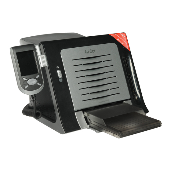
2-3 Mechanism 2-3-1 Introduction The following picture shows the profile of S4XX SERIES (Fig. 1). There are three components, which can be moved or opened by user, as below: Door Button Push down the button, and then the front cover will be opened. At this status, user can install the ribbon cassette, or remove it from the printer (see Fig. - Page 32 Fig. 2 Front Cover Open Status Fig. 3 Paper Cassette Moving Status...
- Page 33 Fig. 4 Back door dust-proof Status Back to Contents...
-
Page 34: Transmission
2-3-2 Transmission In order to drive the ribbon, to feed the paper and to control cam position, three motors are used in S4XX SERIES (Fig. 5). The purpose of three motors and devices are as below: ADF & RIBBON MOTOR Move paper forwards to capstan roller when feeding paper and supply a torque to drive the ribbon during printing process. -
Page 35: Paper Take-Up Section Drive Mechanism
2-3-3 Paper Take-up Section Drive Mechanism Fig. 6 Paper Take-up Section Drive Mechanism (1) Auto Document Feeder (ADF) is illustrated as Fig. 6, 7 and Fig. 8, mainly the Paper Lift Device lefts up the paper in the paper cassette, and then the Paper Pick-up Device feeds the paper into the printer. - Page 36 Fig. 8 Paper Path Description Regarding the ADF transmission, it is illustrated as Fig. 9. When the ADF Motor moves clockwise, it drives Gear 1 moving anticlockwise, and swings the Arm-Swing by friction. When Swing Gear and Gear 2 engaged, Swing Gear starts to rotate clockwise and drives Gear 2 moving anticlockwise, and then drives Gear 3 moving clockwise.
-
Page 37: Ribbon Take-Up Section Drive Mechanism
2-3-4 Ribbon Take-up Section Drive Mechanism When ADF device feeds the paper into the machine and becomes ready position to print, the next action is to search the ribbon. (In order to avoid getting ribbon jammed) the power for rotating the ribbon is provided by (as shown as Fig. 10): ADF Motor rotates anticlockwise, and drives Gear 1 rotating clockwise and swings the Arm-Swing by friction. - Page 38 Regarding the theory of torque generation, it is shown as Fig. 11, 12. When Swing Gear touches Gear 1, and Gear 1, Gear2 and Gear 3 start to move simultaneously, Gear 3 will drive two pieces of felts near Gear 3. These two felts rub against to Base-TQL and Gear 3 separately, this friction makes Base-TQL rotating and provides a regular torque to make Ribbon Driver to roll the ribbon;...
-
Page 39: Paper Movement Mechanism
2-3-5 Paper Movement Mechanism Arm_Swing_Rewind Gear 2 Belt 1 Gear 1 Pulley Capstan Pulley 1 Swing_Gear_Exit Belt 2 Gear Exit Pulley 2 Fig. 13 Paper Movement Drive Mechanism In order to print a photo completely, the paper has to go back and forth for four times. The force for these movements is totally coming from Capstan Motor;... -
Page 40: Platen Position And Pinch Separation Mechanism
2-3-6 Platen Position and Pinch Separation Mechanism When the printer is working normally, TPH must press on Platen Roller tightly, and Pinch Roller must press on Capstan Roller. During the paper movement and ribbon search procedures, TPH must stays away from Platen Roller. Besides, in order to avoid deforming Pinch Roller, Capstan Roller and Pinch Roller must be separated when the machine is standby. - Page 41 Scotch yoke Clutch_RBN_R ewind Bushing Platen 1’ Bushing Platen 1 Link 2 Link 1 Fig. 15 Platen Position and Pinch Separation Mechanism (2) Back to Contents...
-
Page 42: Firmware
As the firmware is stored in the ICs of the main board, you need to use the easy to use BurnFW.exe application in order to update the printer’s firmware. Firmware updates can easily be downloaded from the HiTi support website: Go to www.hi-ti.com; then find the ‘Support’ section. -
Page 43: Error Messages
2-4-3 Error Messages: The firmware controlled Status LED shows the error status: Green Signal Light: Stable: Printer is ready for processing job Blinking slowly: Printer is processing job or initializing after power on Blinking fast: Printer is writing firmware IMPORTANT: NEVER TURN THE PRINTER OFF WHILE ANY LIGHT IS BLINKING OR WHILE YOU CAN STILL HEAR OPERATIONAL SOUNDS FROM THE PRINTER Orange Signal Light: LED blinking times... - Page 44 Paper mismatch Confirm paper and ribbon type 1.Clean Cam sensor 2.Reassembly Cam gear Cam error 3.Change Cam sensor 4.Change Cam gear Nvram error Change Main BD Change Ribbon Ribbon Chip Error Change IC Ribbon Sensor BD Asic error Change Main BD 1.
-
Page 45: Chapter 3: Disassembly
Chapter 3: Disassembly 3-1 Safety Instructions Read these instructions carefully. Save these instructions for future reference. Follow all warnings and instructions marked on the printer. Unplug the printer from the wall outlet before disassembly. Do not place the printer on an unstable cart, stand, or table. The printer may get damaged by a fall. -
Page 46: Tools
3-2 Tools Tweezers IC Clamp Screwdriver– minus Wire Cutter Back to Contents Screwdriver– plus... -
Page 47: Do Not Disassemble These Parts
3-3 Do not Disassemble these Parts HiTi strictly prohibits anyone to disassemble the Bracket-idle. The part needs to be calibrated by a specific calibration device and cannot be repaired on site. Bracket-idle Back to Contents... -
Page 48: Disassembly List
3-4 Disassembly List Controller 3-4-1 Controller Board and Controller Cable Case 3-4-2 Ribbon Door and Case front 3-4-3 Case Back 3-4-4 Power Board and Sheet_Power_Board 3-4-5 Main Board 3-4-6 TPH Board, Fan and Ribbon LED_B Motor 3-4-7 ADF Motor, Cam Motor and Capstan Motor Wire , Cable,LED &... -
Page 49: Rollers
Rollers 3-4-14 Capstan Roller and Pinch Roller Others 3-4-15 TPH 3-4-16 TQL Back to Contents... -
Page 50: Controller Board And Controller Cable
3-4-1 Controller Board and Controller Cable Controller Board S400 P/N: 45.P1804.021 S420 P/N: 47.P2008.001 Controller Cable S400 P/N:40.P1801.001 S420 P/N:40.P2001.R02 Unscrew 4 screws from controller case back... - Page 51 Unplug connector of controller cable from controller board Unplug 2 connectors to LCD from controller board Controller Board...
- Page 52 Controller Cable Back to Disassembly List...
-
Page 53: Ribbon Door And Case Front
3-4-2 Ribbon door and Case front Ribbon Door S400 P/N: 56.P1841.003 S420 P/N: 56.P2005.011 Case Front P/N: 48.P1810.001 S400 P/N: 48.P1810.001 S420 P/N: 48.P2002.001... - Page 54 Unscrew 3 screws from case back Open ribbon door Release two bosses of both sides from the slide ways of the ribbon door...
- Page 55 Separate case front from case back with chassis (there are two wedges in the bottom of the case front, have to unlock them firstly) Separate ribbon door from case front...
- Page 56 Ribbon Door Case Front Back to Disassembly List...
-
Page 57: Case Back
3-4-3 Case back Case Back S400 P/N: 48.P1809.001 S420 P/N: 48.P2001.001 Remove the Case Front according to 3-4-2 Ribbon door and Case front removal procedure Unscrew 3 screws from chassis... - Page 58 Unplug the connector from main board Separate case back and chassis Unscrew 2 screws from bracket...
- Page 59 Unplug 2 connectors and unscrew the screw from power board Separate case back and power board Case Back Back to Disassembly List...
-
Page 60: Power Board And Sheet_Power_Board
3-4-4 Power Board and Sheet_Power_Board Power Board P/N:44.P18R2.009 Unscrew 2 screws from bracket... - Page 61 Unplug 3 connectors and unscrew 4 screws from power board Separate case back and power board Sheet_Power_Board...
- Page 62 Power Board Back to Disassembly List...
-
Page 63: Main Board
3-4-5 Main Board Main Board S400 P/N: 45.P1801.032 S420 P/N: 45.P20R1.041 S400 S420 Remove the Case Front and Case Back according to 3-4-2 Ribbon door and Case front 3-4-3 Case back removal procedure Unplug all the connectors and unscrew 4 screws from main board... - Page 64 Main Board Back to Disassembly List...
-
Page 65: Tph Board, Fan And Ribbon Led_B
3-4-6 TPH board, Fan and Ribbon LED_B TPH Board-L S400 P/N: 45.P1806.021 S420 P/N: 45.P20R6.011 TPH Board-R S400 P/N: 45.P180H.031 S420 P/N: 45.P20RH.011 TPH Board-L TPH Board-R S400 P/N: 17.F5010.006 S420 P/N: 17.FBP20.CA1 Ribbon LED_B P/N:40.P1806.R02... - Page 66 Unscrew 3 screws from case back Open ribbon door Release two bosses of both sides from the slide ways of the ribbon door...
- Page 67 Unscrew 2 screws and unplug 7 connectors from TPH board Take TPH Board out THP board- L THP board- R...
- Page 68 Unscrew 2 screws from heat sink...
- Page 69 Unscrew 2 screws from ribbon LED_B Ribbon LED_B Back to Disassembly List...
-
Page 70: Adf Motor, Cam Motor And Capstan Motor
3-4-7 ADF Motor, Cam Motor and Capstan Motor ADF Motor P/N: 17.MBP18.BN2 Cam Motor P/N: 17.MCP18.BN2 Capstan Motor P/N:17.MAP18.BM2 Remove the Case Front and Case Back according to 3-4-2 Ribbon door and Case front 3-4-3 Case back removal procedure... -
Page 71: Adf Motor
Unscrew the screws from motor frame Cam motor Capstan motor ADF motor Unplug the connector from main board Cam motor ADF motor Capstan motor... - Page 72 Cam Motor Capstan Motor...
- Page 73 ADF Motor Back to Disassembly List...
-
Page 74: Status Led
3-4-8 Status LED Status LED P/N: 40.P1804.R01 Remove the Case Front and Case Back according to 3-4-2 Ribbon door and Case front 3-4-3 Case back removal procedure Unplug the connector and unscrew the screw from main board... - Page 75 Status LED Back to Disassembly List...
-
Page 76: Cam Sensor
3-4-9 Cam Sensor Cam Sensor S400 P/N: 40.P1817.001 S420 P/N: 40.P1817.R03 Remove the Case Front and Case Back according to 3-4-2 Ribbon door and Case front 3-4-3 Case back removal procedure Unplug the connector and unscrew 4 screws from main board... - Page 77 Unscrew 2 screws from cam sensor Cam Sensor Back to Disassembly List...
-
Page 78: Cover Open Sensor
3-4-10 Cover Open Sensor Cover Open Sensor P/N: 40.P1816.R03 Remove the Case Front and Case Back according to 3-4-2 Ribbon door and Case front 3-4-3 Case back removal procedure Unscrew the screw from Cover open sensor... - Page 79 Unplug the connector from main board Cover Open Sensor Back to Disassembly List...
-
Page 80: Jam Sensor
3-4-11 Jam Sensor Jam Sensor S400 P/N: 40.P1813.R01 S420 P/N: 40.P1813.R02 Remove the Case Front and Case Back according to 3-4-2 Ribbon door and Case front 3-4-3 Case back removal procedure Unscrew the screw from jam sensor... - Page 81 Unplug the connector from main board Jam Sensor Back to Disassembly List...
-
Page 82: Ribbon Sensor_B, Le Sensor And Tray Front
3-4-12 Ribbon Sensor_B, LE Sensor and Tray Front Ribbon Sensor_B P/N: 40.P1812.R01 LE Sensor P/N: 40.P1815.R02 Tray Front P/N: 56.P1812.001 Remove the Case Front and Case Back according to 3-4-2 Ribbon door and Case front 3-4-3 Case back removal procedure... - Page 83 Unscrew 5 screws from motor frame Unscrew 2 screws from tray front Remove the ribbon holder...
- Page 84 Unplug the connectors from main board Ribbon sensor_B LE sensor Take Tray Front off...
- Page 85 Unscrew the screw from tray front Take Ribbon sensor_B out from tray front...
- Page 86 Unscrew 2 screws from LE sensort Take LE Sensor out Back to Disassembly List...
-
Page 87: Cassette Sensor And Ribbon Sensor_F
3-4-13 Cassette Sensor and Ribbon Sensor_F Cassette Sensor P/N: 40.P1811.001 *Cassette Sensor has been canceled for S420 Ribbon Sensor_F P/N: 40.P1810.R01 * Ribbon Sensor_F has been canceled CARD MODULE BD S420 M31 ROHS P/N: 45.P20R8.M31 Remove the Case Front and Case Back according to 3-4-2 Ribbon door and Case front 3-4-3 Case back removal procedure... - Page 88 Unscrew 5 screws from motor frame Unscrew 2 screws from carrier back Remove the ribbon holder...
- Page 89 Remove 2 tabs on carrier back Take carrier back out Unscrew 3 screws from carrier back...
- Page 90 Unplug the connectors from main board Ribbon sensor_F Cassette sensor Cassette Sensor...
- Page 91 Ribbon Sensor_F Back to Disassembly List...
-
Page 92: Capstan Roller And Pinch Roller
3-4-14 Capstan roller and Pinch roller Capstan Roller P/N: 53.P1809.002 Pinch Roller P/N: 59.P0112.003 Remove the Case Front and Case Back according to 3-4-2 Ribbon door and Case front 3-4-3 Case back removal procedure... - Page 93 Unscrew 4 screws from main board Unscrew 5 screws from motor frame...
- Page 94 Take the c-ring off Pull Capstan roller out...
- Page 95 Capstan Roller Release pinch spring. (Apply caution when you pull down the spring. Do not stretch the spring and do not pull too hard)
- Page 96 Pull bushing pinch upwards and push pinch roller backwards Push pinch roller upwards and pull pinch roller...
- Page 97 Pinch Roller Back to Disassembly List...
-
Page 98: Tph
3-4-15 TPH P/N: 37.P4740.T03 Remove the Case Front according to 3-4-2 Ribbon door and Case front Use several pieces of detachable boundary to measure the gap By this way, we can get the approximate distance of the gap when we assemble the TPH. detachable boundaries... - Page 99 Unplug 2 flat cables and unscrew 2 screws from TPH BD Unscrew 2 screws behind the TPH BD...
- Page 100 TPH Assembly Put new TPH on the linkage, align the gap by detachable boundaries and screw 2 screws behind the TPH BD. detachable boundaries...
- Page 101 Plug 2 flat cables and screw 2 screws on TPH BD Align the gap by detachable boundaries again then check the printout. If the density is low, adjust the distance of the gap (±1or ±2 piece of detachable boundaries).
- Page 102 detachable boundaries Back to Disassembly List...
-
Page 103: Tql
3-4-16 TQL P/N:47.P1801.011 Remove the Case Front and Case Back according to 3-4-2 Ribbon door and Case front 3-4-3 Case back removal procedure Unscrew 5 screws from motor frame... - Page 104 Take e-ring out Take TQL out Back to Disassembly List...
-
Page 105: Chapter 4: Adjustments
Chapter 4: Adjustments 4-1 Safety Instructions Read these instructions carefully. Save these instructions for future reference. Follow all warnings and instructions marked on the product. Unplug this product from the wall outlet before cleaning. Do not place this product on an unstable cart, stand, or table. The product may fall, causing serious damage to the product Openings in the cabinet and the bottom are provided for ventilation;... -
Page 106: Tools
4-2 Tools Screwdriver- plus Digital Meter Glue (screw lock) -
Page 107: Htools (Trouble Shooting Program)
HTools (Trouble shooting program) New yellow frame Printed magenta frame (printed whole black) -
Page 108: Vr On Main Board
4-3 VR on Main Board VR on Main Board is used to adjust the voltage output from ribbon sensor. There are 2 sets of ribbon sensor and LED in S400, but only the back set has the auto-calibration function. Voltage test and adjust method Manually wind the ribbon to a new yellow frame, and insert it into the printer. - Page 109 Touch/ contact the red probe with the solder of black cable on the connector of ribbon sensor. Ribbon VR_B on sensor_F Main-board VR_F on Main-board Ribbon Ground sensor_B Test and adjust the VR1 and VR2 as possible as close to 3.00V Check with a printed (whole black) magenta frame.
-
Page 110: Vr On Power Board
4-4 VR on Power Board Voltage test and adjust method 1. Before replacing TPH, please print reference charts first (P1). 2. After replacing TPH, take multi-meter and select DC voltage. 3. Contact black probe with the solder of the brown pin on power connector. 4. -
Page 111: Formula And Table
Black pin Brown pin VR on Power-board TPH value Label & Number Formula and table Formula: V×V/R=0.080 V: voltage on power connector R: TPH Value TPH Value Volt TPH Value Volt TPH Value Volt TPH Value Volt 5100 20.20 6100 22.09 7100 23.83... -
Page 112: Cam Position
4-5 Cam Position The Cam Platen Error is very unlikely and the exact cause of that error has not yet been established. In the rather unlikely event of a cam/platen error the gears (on both sides) are no longer adjusted properly and are no longer synchronous and hence need to be re-adjusted and re-aligned. -
Page 113: Right Side
Right Side As an illustration, there are three holes on the gears and three holes on the chassis under the gears. Please align each two holes for alignment. Please do the right side and the left side alignment at the same time. Back to Contents... -
Page 114: Chapter 5: Ecr/Ecn Of S420 Lcd Modification
Chapter 5: ECR/ECN of S420 LCD Modification On 2008 week35, HiTi upgraded S420 LCD and Controller Board. The way to identify the NEW LCD version: Take out the LCD panel from controller. Check the label backside. If the label shows “TD025THEEA”... -
Page 115: Chapter 6: Contact Information
Chapter 6: Contact Information Website: www.hi-ti.com Email: service2@hi-ti.com Taiwan (Asia) - Headquarters HiTi Digital, Inc. 20F., No.100, Sec. 2, Roosevelt Rd., Taipei City 100 , Taiwan TEL: +886-2-2363-8833 FAX: +886-2-2362-1319 China 18 QunXing Road One, Suzhou Industrial Park, 215006, China, PRC...
Need help?
Do you have a question about the S400 and is the answer not in the manual?
Questions and answers