
Related Manuals for IBASE Technology MI981


Summary of Contents for IBASE Technology MI981
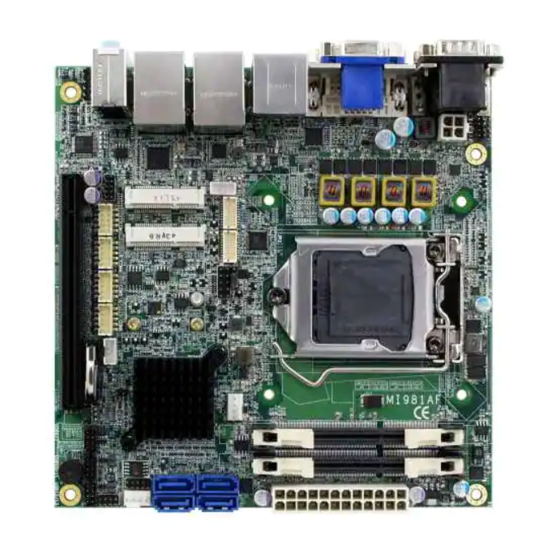
- Page 1 MI981 Intel® Q87 Based Mini-ITX board Mini ITX Motherboard USER’S MANUAL Version 1.0...
- Page 2 Generation Core DC/QC Processor are registered trademarks of Intel Corporation. Microsoft Windows is a registered trademark of Microsoft Corporation. Fintek is a registered trademark of Fintek Electronics Corporation. All other product names or trademarks are properties of their respective owners. MI981 User’s Manual...
-
Page 3: Table Of Contents
MI981 Specifications ............2 Board Dimensions ............... 4 Installations ............5 Installing the Memory ............6 Setting the Jumpers ............. 7 Connectors on MI981 ............12 BIOS Setup ............25 Drivers Installation ........51 Intel Chipset Software Installation Utility ......52 VGA Drivers Installation .......... - Page 4 This page is intentionally left blank. MI981 User’s Manual...
-
Page 5: Introduction
Expansion is provided by PCIe(16x), one full sized MiniPCIe and a half sized MiniPCIe. Onboard connectors support 4x SATA III, 4x or 6x USB 2.0 depending on the MI981 model and 6x COM ports. The board measures 170mm x 170mm. -
Page 6: Mi981 Specifications
CPU FAN x 1(PWN Fan type, 4-pin connector) SYS fan x 1(PWM Fan type, 4-pin connector)] Digital IO 4 in & 4 out ® IAMT 9.1 Intel Active Management Technology ver. 9.1 TPM 1.2 Infineon SLB9655 MI981 User’s Manual... - Page 7 4 pin type (+12V only) Other - LAN Wakeup - iSMART 3.0 Environment Operation Temperature: 0~60 degree C Storage Temperature: -20~80 degree C Relative humidity: 0~90%, non-condensing Board Size 170mm x 170mm Operation Windows 7, Windows 8, Linux System MI981 User’s Manual...
-
Page 8: Board Dimensions
INTRODUCTION Board Dimensions MI981 User’s Manual... -
Page 9: Installations
INSTALLATIONS Installations This section provides information on how to use the jumpers and connectors on the MI981 in order to set up a workable system. The topics covered are: Installing the Memory ................6 Setting the Jumpers ................7 Connectors on MI981 ................12... -
Page 10: Installing The Memory
INSTALLATIONS Installing the Memory The MI981 board supports two DDR3 memory modules for a maximum total of 16GB in DDR3 SODIMM memory type. Installing and Removing Memory Modules To install the DDR3 modules, locate the memory slot on the board and perform the following steps: 1. -
Page 11: Setting The Jumpers
INSTALLATIONS Setting the Jumpers Jumpers are used on MI981 to select various settings and features according to your needs and applications. Contact your supplier if you have doubts about the best configuration for your needs. The following lists the connectors on MI981 and their respective functions. -
Page 12: Jumper Locations On Mi981
INSTALLATIONS Jumper Locations on MI981 Jumpers on MI981 ................Page JP1: COM2 RS232 RI/+5V/+12V Power Setting ........9 JP2: COM1 RS232 RI/+5V/+12V Power Setting ........9 JP3: LVDS Panel Power Selection ............10 JP4: Power Good Selection ..............10 JP5: Flash Descriptor Security Override (Factory use only) ....11 JBAT1: Clear CMOS Contents ............ -
Page 13: Jp1: Com2 Rs232 Ri/+5V/+12V Power Setting
INSTALLATIONS JP1: COM2 RS232 RI/+5V/+12V Power Setting Setting Function Pin 1-3 +12V Short/Closed Pin 3-4 Short/Closed Pin 3-5 Short/Closed JP2: COM1 RS232 RI/+5V/+12V Power Setting Setting Function Pin 1-3 +12V Short/Closed Pin 3-4 Short/Closed Pin 3-5 Short/Closed MI981 User’s Manual... -
Page 14: Jp3: Lvds Panel Power Selection
INSTALLATIONS JP3: LVDS Panel Power Selection Setting Panel Voltage Pin 1-2 3.3V (default) Short/Closed Pin 2-3 Short/Closed JP4: Power Good Selection Function Short Factory use only Open Normal MI981 User’s Manual... -
Page 15: Jp5: Flash Descriptor Security Override (Factory Use Only)
INSTALLATIONS JP5: Flash Descriptor Security Override (Factory use only) Flash Descriptor Security Override Open Disabled (Default) Close Enabled JBAT1: Clear CMOS Contents JBAT1 Setting Function Pin 1-2 Normal Short/Closed Pin 2-3 Clear CMOS Short/Closed MI981 User’s Manual... -
Page 16: Connectors On Mi981
INSTALLATIONS Connectors on MI981 Connector Locations on MI981 ............13 CN1: COM1 and COM2 Serial Ports........... 14 CN2: VGA and DVI-D Connector ............14 CN3: USB3.0 Connector ..............15 CN4: DP Connector ................15 CN5: Gigabit LAN (Intel I217LM) / USB3.0 ........15 CN6, CN7, CN8, CN9: SATA Connectors .......... -
Page 17: Connector Locations On Mi981
INSTALLATIONS Connector Locations on MI981 MI981 User’s Manual... -
Page 18: Cn1: Com1 And Com2 Serial Ports
CN1: COM1 and COM2 Serial Ports Pin # Signal Name RS-232 R2-422 RS-485 DATA- DATA+ Ground Ground Ground CN2: VGA and DVI-D Connector Signal Name Pin # Pin # Signal Name Green Blue N.C. N.C. N.C. DDCDATA HSYNC VSYNC DDCCLK MI981 User’s Manual... -
Page 19: Cn3: Usb3.0 Connector
DATA 1+ GROUND N.C. N.C. DDC POWER GROUND CN3: USB3.0 Connector CN4: DP Connector CN5: Gigabit LAN (Intel I217LM) / USB3.0 CN6, CN7, CN8, CN9: SATA Connectors CN10: Gigabit LAN (Intel I211AT) / USB3.0 CN11: HD Audio Connector MI981 User’s Manual... -
Page 20: J1: Atx 12V Power Connector
Signal Name Ground Ground +12V +12V J4: ATX Power Supply Connector Signal Name Pin # Pin # Signal Name 3.3V 3.3V -12V 3.3V Ground Ground PS-ON Ground Ground Ground Ground Ground Power good 5VSB +12V +12V Ground +3.3V MI981 User’s Manual... -
Page 21: J5, J6: Lvds Connectors
INSTALLATIONS J5, J6: LVDS Connectors Signal Name Pin # Pin # Signal Name LCD_PWR LCD_PWR LD3+ LD3- CLK+ CLK- LD2+ LD2- LD1+ LD1- LD0+ LD0- J7: Digital I/O Signal Name Signal Name OUT3 OUT1 OUT2 OUT0 MI981 User’s Manual... -
Page 22: J8: Lcd Backlight Connector
INSTALLATIONS J8: LCD Backlight Connector Pin # Signal Name Backlight Power Backlight Enable Brightness Control Ground J9: Mini PCIE/mSATA Connector J10: Mini PCIE Connector MI981 User’s Manual... -
Page 23: J11: Spi Flash Connector (Factory Use Only)
INSTALLATIONS J11: SPI Flash Connector (Factory use only) J12: MCU Flash Connector (factory use only) J13: Debug 80 Port Connector (factory use only) MI981 User’s Manual... -
Page 24: J14: Front Panel Function Connector
The reset switch allows the user to reset the system without turning the main power switch off and then on again. Orientation is not required when making a connection to this header. Power LED: Pins 7 and 8 Pin # Signal Name MI981 User’s Manual... -
Page 25: J15, J16, J17, J18: Com3/Com4/Com5/Com6 Connector
RXD, Receive data TXD, Transmit data DTR, Data terminal ready GND, ground DSR, Data set ready RTS, Request to send CTS, Clear to send RI, Ring indicator Not Used J19, J20, J21: USB Connectors Signal Name Signal Name MI981 User’s Manual... -
Page 26: J22: Audio Front Header
INSTALLATIONS J22: Audio Front Header Signal Name Pin # Pin # Signal Name MIC2_L Ground MIC2_R Presence# Line2_R MIC2_ID Sense Line2_L Line2_ID PCIE1: PCI-E X16 Slot MI981 User’s Manual... -
Page 27: Cpu_Fan1: Cpu Fan Power Connector
INSTALLATIONS CPU_FAN1: CPU Fan Power Connector Pin # Signal Name Ground +12V Rotation detection Control SYS_FAN1: System Fan1 Power Connector Pin # Signal Name Ground +12V Rotation detection Control MI981 User’s Manual... - Page 28 INSTALLATIONS This page is intentionally left blank. MI981 User’s Manual...
-
Page 29: Bios Setup
The topics covered in this chapter are as follows: BIOS Introduction ................26 BIOS Setup ..................26 Advanced Settings ................27 Chipset Settings ................... 42 Boot Settings..................47 CSM parameters .................. 48 Security Settings .................. 49 Save & Exit Settings ................50 MI981 User’s Manual... -
Page 30: Bios Introduction
These defaults have been carefully chosen by both AMI and your system manufacturer to provide the absolute maximum performance and reliability. Changing the defaults could cause the system to become unstable and crash in some cases. MI981 User’s Manual... -
Page 31: System Language
► LVDS (eDP/DP) Configuration F1: General Help ► iSmart Controller 3.1 F2: Previous Values ► AMT Configuration F3: Optimized Defaults ► USB Configuration F4: Save & Exit ► F81866 Super IO Configuration ESC: Exit ► F81866 H/W Monitor MI981 User’s Manual... -
Page 32: Pci Subsystem Settings
VGA Palette Snoop Enables or disables VGA Palette Registers Snooping. PERR# Generation Enables or disables PCI device to generate PERR#. SERR# Generation Enables or disables PCI device to generate SERR#. PCI Express Settings Change PCI Express devices settings. MI981 User’s Manual... -
Page 33: Maximum Payload
BIOS to select the value. ASPM Support Set the ASPM Level: Force L0s – Force all links to L0s State: AUTO – BIOS auto configure: DISABLE – Disables ASPM. Extended Synch If ENABLED allows generation of Extended Synchronization patterns. MI981 User’s Manual... - Page 34 On non-PCI Express aware OS’s (Pre Windows Vista) some devices may not be correctly reinitialized after S3.Enabling this restore PCI Express device configuration on S3 resume Warning: Enabling this may cause issues with other hardware after S3 resume. MI981 User’s Manual...
-
Page 35: Acpi Settings
This option may be not effective with some OS. ACPI Sleep State Select ACPI sleep state the system will enter, when the SUSPEND button is pressed. Lock Legacy Resources Enabled or Disabled Lock of Legacy Resources. S3 Video Repost Enable or disable S3 Video Repost. MI981 User’s Manual... -
Page 36: Trusted Computing
Enable/Disable Security Device. NOTE: Your Computer will reboot during restart in order to change State of the Device. Pending operation Schedule an Operation for the Security Device. NOTE: Your Computer will reboot during restart in order to change State of Security Device. MI981 User’s Manual... - Page 37 ↑↓ Select Item Enter: Select Change Opt. F1: General Help F2: Previous Values F3: Optimized Defaults F4: Save & Exit ESC: Exit Wake up by Ring / Wake up by PCIE WAKE# The options are Disabled and Enabled. MI981 User’s Manual...
-
Page 38: Cpu Configuration
OS Intel Virtualization Technology When enabled, a VMM can utilize the additional hardware capabilities provided by Vanderpool Technology. Boot Performance Mode Select the performance state that the BIOS will set before OS handoff. EIST Enabled/Disabled Intel Speedstep. MI981 User’s Manual... -
Page 39: Sata Configuration
SATA Mode Selection Determines how SATA controller(s) operate. (1) IDE Mode. (2) AHCI Mode. (3) RAID Mode. (MI981AF only) SATA Controller Speed Indicates the maximum speed the SATA controller can support. Hot Plug Designates this port as Hot Pluggable. MI981 User’s Manual... -
Page 40: Acpi Shutdown Temperature
LVDS (eDP/DP) Configuration → ← Select Screen DP/eDP LVDS Control Disable ↑↓ Select Item Enter: Select Change Opt. F1: General Help F2: Previous Values F3: Optimized Defaults F4: Save ESC: Exit DP/eDP LVDS Control The default setting is Disabled. MI981 User’s Manual... - Page 41 This field sets the system power status whether Disable or Enable when power returns to the system from a power failure situation. Temperature Guardian Generate the reset signal when system hangs up on POST Schedule Slot 1 / 2 Setup the hour/minute for system power on. MI981 User’s Manual...
- Page 42 Hide Un-Configure ME Configuration OEMFLag Bit 6: Hide Un-Configure ME without password Confirmation Prompt. Un-Configure ME OEMFLag Bit 15: Un-Configure ME without password. Amt Wait Timer Set timer to wait before sending ASF_GET_BOOT_OPTIONS. Activate Remote Assistance Process Trigger CIRA boot. MI981 User’s Manual...
-
Page 43: Usb Configure
DISABLE option will keep USB devices available only for EFI applications. USB3.0 Support Enable/Disable USB3.0 (XHCI) Controller support. XHCI Hand-off This is a workaround for OSes without XHCI hand-off support. The XHCI ownership change should be claimed by XHCI driver. MI981 User’s Manual... -
Page 44: Usb Mass Storage Driver Support
F2: Previous Values F3: Optimized Default ► Serial Port 6 Configuration F4: Save ESC: Exit Serial Port Configuration Set Parameters of Serial Ports. User can Enable/Disable the serial port and Select an optimal settings for the Super IO Device. MI981 User’s Manual... - Page 45 70 ℃ 80 ℃ 90 ℃ Temperatures/Voltages These fields are the parameters of the hardware monitoring function feature of the motherboard. The values are read-only values as monitored by the system and show the PC health status. MI981 User’s Manual...
-
Page 46: Chipset Settings
Wake on LAN Enable or disable integrated LAN to wake the system. (The Wake On LAN cannot be disabled if ME is on at Sx state.) SLP_S4 Assertion Width Select a minimum assertion width of the SLP_S4# signal. MI981 User’s Manual... -
Page 47: Pci Express Configuration
DMI Link Extended Synch Control The control of Extended Synch on SB side of the DMI Link. PCIe-USB Glitch W/A PCIe-USB Glitch W/A for bad USB device(s) connected behind PCIE/PEG port. Subtractive Decode Enable or disable PCI Express Subtractive Decode. MI981 User’s Manual... -
Page 48: Pch Azalia Configuration
F3: Optimized Defaults F4: Save & Exit ESC: Exit Azalia Control Detection of the Azalia device. Disabled = Azalia will be unconditionally disabled. Enabled Azalia will be unconditionally Enabled. Auto = Azalia will be enabled if present, disabled otherwise. MI981 User’s Manual... -
Page 49: Graphics Configuration
DVMT Pre-Allocated ESC: Exit DVMT Total Gfx Mem 256MB Primary Display Select which of IGFX/PEG/PCI graphics device should be Primary Display or select SG for switchable Gfx. Primary PEG Select PEG0/PEG1/PEG2/PEG3 Graphics device should be Primary PEG. MI981 User’s Manual... -
Page 50: Internal Graphics
DIMM#3 Not Present Enter: Select CAS Latency (tCL) Change Field F1: General Help Minimum delay time CAS to RAS (tRCDmin) F2: Previous Values F3: Optimized Default Row Precharge (tRPmin) F4: Save ESC: Exit Active to Precharge (tRASmin) MI981 User’s Manual... -
Page 51: Boot Settings
Enables/Disables Quiet Boot option. Fast Boot Enables/Disables boot with initialization of a minimal set of devices required to launch active boot option. Has no effect for BBS boot options. FIXED BOOT ORDER Priorities Sets the system boot order. MI981 User’s Manual... -
Page 52: Csm Parameters
Controls the execution of UEFI and Legacy Storage OpROM. Launch Video OpROM policy Controls the execution of UEFI and Legacy Video OpROM. Other PCI device ROM priority For PCI devices other than Network, Mass storage or Video defines which OpROM to launch. MI981 User’s Manual... -
Page 53: Security Settings
Enter: Select Minimum length Change Field Maximum length F1: General Help F2: Previous Values Administrator Password F3: Optimized Default User Password F4: Save ESC: Exit Administrator Password Set Setup Administrator Password. User Password Set User Password. MI981 User’s Manual... -
Page 54: Save & Exit Settings
Discard Changes done so far to any of the setup options. Restore Defaults Restore/Load Defaults values for all the setup options. Save as User Defaults Save the changes done so far as User Defaults. Restore User Defaults Restore the User Defaults to all the setup options. MI981 User’s Manual... -
Page 55: Drivers Installation
LAN Drivers Installation ..............55 Intel® Management Engine Interface ..........56 Intel® USB 3.0 Drivers ............... 57 IMPORTANT NOTE: After installing your Windows operating system, you must install first the Intel Chipset Software Installation Utility before proceeding with the drivers installation. MI981 User’s Manual... -
Page 56: Intel Chipset Software Installation Utility
4. Click Yes to accept the software license agreement and proceed with the installation process. 5. On the Readme File Information screen, click Next to continue the installation. 6. The Setup process is now complete. Click Finish to restart the computer and for changes to take effect. MI981 User’s Manual... -
Page 57: Vga Drivers Installation
Intel® HD Graphics Driver. 5. On the screen shown below, click Install to continue. 6. On the Setup Progress screen, click Next to continue. 7. Setup complete. Click Finish to restart the computer and for changes to take effect. MI981 User’s Manual... -
Page 58: Realtek Hd Audio Driver Installation
Driver. 2. On the Welcome to the InstallShield Wizard screen, click Next to proceed with and complete the installation process. 3. The InstallShield Wizard Complete. Click Finish to restart the computer and for changes to take effect. MI981 User’s Manual... -
Page 59: Lan Drivers Installation
6. Click the checkbox for Drivers in the Setup Options screen to select it and click Next to continue. 7. The wizard is ready to begin installation. Click Install to begin the installation. 8. When InstallShield Wizard is complete, click Finish. MI981 User’s Manual... -
Page 60: Intel® Management Engine Interface
Management Engine Components, click the checkbox for Install Intel® Control Center & click Next. 3. Click Yes to to agree with the license agreement. 4. When the Setup Progress screen appears, click Next. Then, click Finish when the setup progress has been successfully installed. MI981 User’s Manual... -
Page 61: Intel® Usb 3.0 Drivers
4. On the Readme File Information screen, click Next to continue the installation of the Intel® USB 3.0 eXtensible Host Controller Driver. 5. When the Setup Progress screen appears, click Next. Setup complete. Click Finish to restart the computer and for changes to take effect. MI981 User’s Manual... - Page 62 DRIVER INSTALLATION This page is intentionally set blank. MI981 User’s Manual...
-
Page 63: Appendix
Intel(R) 8 Series/C220 Series SATA AHCI Controller - 8C02 F0C0h-F0C3h Intel(R) 8 Series/C220 Series SATA AHCI Controller - 8C02 F0D0h-F0D7h Intel(R) 8 Series/C220 Series SATA AHCI Controller - 8C02 F0E0h-F0E7h Intel(R) Active Management Technology - SOL (COM7) MI981 User’s Manual... -
Page 64: Interrupt Request Lines (Irq)
IRQ 19 Intel(R) 8 Series/C220 Series SATA AHCI Controller - 8C02 IRQ 19 Intel(R) Active Management Technology - SOL (COM7) IRQ 22 High Definition Audio Controller IRQ 23 Intel(R) 8 Series/C220 Series USB EHCI #1 - 8C26 MI981 User’s Manual... -
Page 65: Watchdog Timer Configuration
Fintek 81866, program abort.\n"); return(1); }//if (SIO == 0) if (argc != 2) printf(" Parameter incorrect!!\n"); return (1); bTime = strtol (argv[1], endptr, 10); printf("System will reset after %d seconds\n", bTime); if (bTime) EnableWDT(bTime); } else DisableWDT(); return 0; MI981 User’s Manual... - Page 66 //--------------------------------------------------------------------------- void DisableWDT(void) unsigned char bBuf; Set_F81866_LD(0x07); //switch to logic device 7 bBuf = Get_F81866_Reg(0xFA); bBuf &= ~0x01; Set_F81866_Reg(0xFA, bBuf); //disable WDTO output bBuf = Get_F81866_Reg(0xF5); bBuf &= ~0x20; bBuf |= 0x40; Set_F81866_Reg(0xF5, bBuf); //disable WDT //--------------------------------------------------------------------------- MI981 User’s Manual...
- Page 67 F81866_UNLOCK); outportb(F81866_INDEX_PORT, F81866_UNLOCK); //--------------------------------------------------------------------------- void Lock_F81866 (void) outportb(F81866_INDEX_PORT, F81866_LOCK); //--------------------------------------------------------------------------- void Set_F81866_LD( unsigned char LD) Unlock_F81866(); outportb(F81866_INDEX_PORT, F81866_REG_LD); outportb(F81866_DATA_PORT, LD); Lock_F81866(); //--------------------------------------------------------------------------- void Set_F81866_Reg( unsigned char REG, unsigned char DATA) Unlock_F81866(); outportb(F81866_INDEX_PORT, REG); outportb(F81866_DATA_PORT, DATA); Lock_F81866(); //--------------------------------------------------------------------------- MI981 User’s Manual...
- Page 68 (F81866_BASE) #define F81866_DATA_PORT (F81866_BASE+1) //--------------------------------------------------------------------------- #define F81866_REG_LD 0x07 //--------------------------------------------------------------------------- #define F81866_UNLOCK 0x87 #define F81866_LOCK 0xAA //--------------------------------------------------------------------------- unsigned int Init_F81866(void); void Set_F81866_LD( unsigned char); void Set_F81866_Reg( unsigned char, unsigned char); unsigned char Get_F81866_Reg( unsigned char); //--------------------------------------------------------------------------- #endif //__F81866_H MI981 User’s Manual...
Need help?
Do you have a question about the MI981 and is the answer not in the manual?
Questions and answers