
Related Manuals for IBASE Technology MI997AF


Summary of Contents for IBASE Technology MI997AF
- Page 1 MI997AF ® Intel 12th Gen Core™ i7/i5/i3 / Celeron Mini-ITX Motherboard User’s Manual Version 1.0 (May 2023)
- Page 2 No part of this publication may be reproduced, copied, stored in a retrieval system, translated into any language or transmitted in any form or by any means, electronic, mechanical, photocopying, or otherwise, without the prior written consent of IBASE Technology, Inc. (hereinafter referred to as “IBASE”). Disclaimer IBASE reserves the right to make changes and improvements to the products described in this document without prior notice.
- Page 3 0.1% by weight (1000 ppm) except for cadmium, limited to 0.01% by weight (100 ppm). • Lead (Pb) • Mercury (Hg) • Cadmium (Cd) • Hexavalent chromium (Cr6+) • Polybrominated biphenyls (PBB) • Polybrominated diphenyl ether (PBDE) MI997AF User’s Manual...
- Page 4 Danger of explosion if the internal lithium-ion battery is replaced by an incorrect type. Replace only with the same or equivalent type recommended by the manufacturer. Dispose of used batteries according to the manufacturer’s instructions or recycle them at a local recycling facility or battery collection point. MI997AF User’s Manual...
- Page 5 Software in use (such as OS and application software, including the version numbers) If repair service is required, you can download the RMA form at http://www.ibase.com.tw/english/Supports/RMAService/. Fill out the form and contact your distributor or sales representative. MI997AF User’s Manual...
-
Page 6: Table Of Contents
HD Audio Connector (CN7) ............ 26 2.5.8 Front Panel Settings Connector (J2) ........27 2.5.9 COM3 (J1) & COM4 (J3) RS-232 Ports ......... 28 2.5.10 DDR5 SO-DIMM Slot (J4 / J7) ..........29 2.5.11 SPI Flash Connector (J5) ............29 MI997AF User’s Manual... - Page 7 BIOS Setup ............53 Introduction ..................54 BIOS Setup ..................54 Main Settings ..................55 Advanced Settings ................55 Chipset Settings ................... 70 Security Settings .................. 73 Boot Settings..................75 Save & Exit Settings ................76 MEBx ....................77 MI997AF User’s Manual...
- Page 8 Appendix ..................79 I/O Port Address Map ................80 Interrupt Request Lines (IRQ).............. 82 Watchdog Timer Configuration ............83 Onboard Connector Types ..............87 MI997AFUSB Power Control Bit Mapping........... 88 viii MI997AF User’s Manual...
- Page 9 This page is intentionally left blank. MI997AF User’s Manual...
-
Page 11: Chapter 1 General Information
Chapter 1 General Information The information provided in this chapter includes: Features Packing List Optional Accessories Specifications Block Diagram Product View Board Dimensions... -
Page 12: Introduction
Introduction The MI997AF Mini ITX motherboard is based on 12th Gen Intel® Core i7/i5/i3™ / Celeron processors. With support for two DDR5 slots accommodating up to 64GB memory, it supports independent displays with HDMI (2.0a), LVDS and 2x DisplayPort(1.4a) (DP++) interface. -
Page 13: Packing List
Audio Cable Cooler 330W Power Adaptor (This is suitable for 45W TDP and 15W TDP CPU skus) 150W Power Adaptor (This is recommended to pair with 15W TDP CPU skus only) Power Cable MI997AF User’s Manual... -
Page 14: Specifications
USB 2.0 2x USB 2.0 via pin header USB 3.X 6x USB 3.2 @ edge connector Serial ATA 2x SATA III Audio Built-in HDA controller+Realtek ALC888S (7.1 ch.) Supports fTPM 12V~24V DC-in, Digital I/O (4-in/4-out), SIM Others socket MI997AF User’s Manual... - Page 15 170mm x 170mm (6.7“x 6.7“) (L x W) Environmental Operating 0 ~ 60 °C (32 ~ 140 °F) Temperature Storage -20 ~ 80 °C (-4 ~ 176 °F) Temperature All specifications are subject to change without prior notice. MI997AF User’s Manual...
-
Page 16: Block Diagram
Block Diagram MI997AF User’s Manual... -
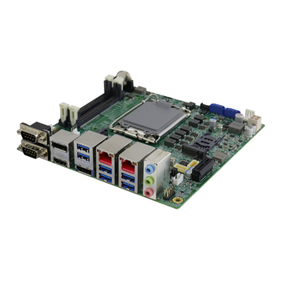
Page 17: Product View
General Information Product View Top View MI997AF User’s Manual... - Page 18 Bottom View MI997AF User’s Manual...
- Page 19 DisplayPort & HDMI Port 3. CN4 DisplayPort 4. CN3 USB 3.2 Connector 5. CN5 2.5 Gigabit LAN (Intel I226-LM) + USB 3.2 6. CN6 2.5 Gigabit LAN (Intel I226-V) + USB 3.2 7. CN7 HD Audio Connector MI997AF User’s Manual...
-
Page 20: Board Dimensions
Board Dimensions MI997AF User’s Manual... -
Page 21: Chapter 2 Hardware Configuration
Chapter 2 Hardware Configuration This section provides information on jumper settings and connectors on the MI997AFand other installation information in order to set up a workable system. The topics covered are: Essential installations Jumper and connector locations Jumper settings and information of connectors... -
Page 22: Essential Installations Before You Begin
Gently push the module in an upright position until the clips of the slot close to hold the module in place when the module touches the bottom of the slot. To remove the module, press the ejector tabs at both ends outwards. MI997AF User’s Manual... -
Page 23: Setting The Jumpers
1 2 3 When two pins of a jumper are encased in a jumper cap, this jumper is closed, i.e., turned On. When a jumper cap is removed from two jumper pins, this jumper is open, i.e., turned Off. MI997AF User’s Manual... -
Page 24: Jumper & Connector Locations
Jumper & Connector Locations MI997AF User’s Manual... - Page 25 Hardware Configuration MI997AF User’s Manual...
-
Page 26: Jumpers Quick Reference
Clear CMOS Clear ME AT/ATX Select LVDS Panel Power Selection LVDS Power Brightness Selection Sierra EM919x 5G card USB/PCIe Select Flash Descriptor Security Override PWM Programming 2.4.1 Clear CMOS Contents (JP1) Function Pin closed Illustration Normal Clear CMOS MI997AF User’s Manual... -
Page 27: Clear Me Contents (Jp2)
Hardware Configuration 2.4.2 Clear ME Contents (JP2) Function Pin closed Illustration Normal Clear ME 2.4.3 ATX & AT Power Mode Selection (JP3) Function Pin closed Illustration (default) MI997AF User’s Manual... -
Page 28: Lvds Panel Power Selection (Jp4)
2.4.4 LVDS Panel Power Selection (JP4) Function Pin closed Illustration 3.3V (default) 2.4.5 LVDS Power Brightness Selection (JP5) Function Pin closed Illustration 3.3V (default) MI997AF User’s Manual... -
Page 29: Sierra Em9191 5G Card Usb/Pcie Select (Jp6)
Hardware Configuration 2.4.6 Sierra EM9191 5G Card USB/PCIe Select (JP6) Function Pin closed Illustration PCIe (default) MI997AF User’s Manual... -
Page 30: Flash Descriptor Security Override (J10)
2.4.7 Flash Descriptor Security Override (J10) Flash Descriptor Illustration Security Override Disabled (default) Open Enabled Close Note: J10 is for factory use only. MI997AF User’s Manual... -
Page 31: Pwm Programming (J11)
Hardware Configuration 2.4.8 PWM Programming (J11) Note: J11 is for factory use only. MI997AF User’s Manual... -
Page 32: Connectors Quick Reference
(Channel A, Channel B) LCD Backlight Connector SATA Power Connector Audio Pin Header for Chassis Front Panel DC-In Power Connector Factory use only SATA1, SATA2 SATA III Connectors CPU_FAN1, Fan Power Connectors SYS_FAN1 PCIE1 PCIe (x1) Slot MI997AF User’s Manual... -
Page 33: Com1 & Com2 Rs-232/422/485 Ports (Cn1)
RXD, Receive data RTS, Request to send TXD, Transmit data CTS, Clear to send DTR, Data terminal ready RI, Ring indicator Ground COM1/COM2 RS-232/422/485 are jumperless, configurable in BIOS. Signal Name RS-232 RS-422 RS-485 DATA- DATA+ Ground Ground Ground MI997AF User’s Manual... -
Page 34: Displayport & Hdmi Port (Cn2)
2.5.2 DisplayPort & HDMI Port (CN2) 2.5.3 USB 3.2 Connector (CN3) MI997AF User’s Manual... -
Page 35: Displayport (Cn4)
Hardware Configuration 2.5.4 DisplayPort (CN4) 2.5.5 2.5 Gigabit LAN (Intel I226-LM) + USB3.2 (CN5) MI997AF User’s Manual... -
Page 36: Gigabit Lan (Intel I226-V) + Usb3.2 (Cn6)
2.5.6 2.5 Gigabit LAN (Intel I226-V) + USB3.2 (CN6) 2.5.7 HD Audio Connector (CN7) MI997AF User’s Manual... -
Page 37: Front Panel Settings Connector (J2)
Orientation is not required when making a connection to this header. Power LED (Pins 7 and 8) This connector connects to the system power LED on control panel. This LED will light when the system turns on. MI997AF User’s Manual... -
Page 38: Com3 (J1) & Com4 (J3) Rs-232 Ports
COM3 (J1) & COM4 (J3) RS-232 Ports Signal Name Signal Name DCD, Data carrier RXD, Receive data detect DTR, Data terminal TXD, Transmit data ready Ground DSR, Data set ready RTS, Request to CTS, Clear to send send RI, Ring indicator Not Used MI997AF User’s Manual... -
Page 39: Ddr5 So-Dimm Slot (J4 / J7)
Hardware Configuration 2.5.10 DDR5 SO-DIMM Slot (J4 / J7) 2.5.11 SPI Flash Connector (J5) Note: J5 is for factory use only. MI997AF User’s Manual... -
Page 40: Port Debug (J6)
2.5.12 80 Port Debug (J6) Note: J6 is for factory use only. 2.5.13 Digital I/O Connector (J8) Signal Signal Ground +5V(0.5A) OUT3 OUT1 OUT2 OUT0 MI997AF User’s Manual... -
Page 41: M2280 Slot (J9, J22)
Hardware Configuration 2.5.14 M.2 M2280 Slot (J9, J22) *J9/J22 supports NVME MI997AF User’s Manual... -
Page 42: E2230 Slot (J12)
2.5.15 M.2 E2230 Slot (J12) *J12 supports USB2.0 & PCIE x1 2.5.16 USB 2.0 Connector (J13) * Connector type: DF11-8S-PA66H Signal Signal VCC(0.5A) Ground Ground VCC(0.5A) MI997AF User’s Manual... -
Page 43: Sim Slot (J14)
Hardware Configuration 2.5.17 SIM Slot (J14) 2.5.18 M.2 B-key 3052 Slot (J15) *J15 supports Sierra EM9191 5G modules. MI997AF User’s Manual... -
Page 44: Lvds Connectors (J17, J16) (Channel A, Channel B)
2.5.19 LVDS Connectors (J17, J16) (Channel A, Channel B) Signal Signal TX0+ TX0- Ground Ground TX1+ TX1- Ground Ground TX2+ TX2- Ground Ground TXC+ TXC- Ground Ground TX3+ TX3- +3.3 / +5V +3.3 / +5V MI997AF User’s Manual... -
Page 45: Lcd Backlight Connector (J18)
Hardware Configuration 2.5.20 LCD Backlight Connector (J18) Signal Name Signal Name +12V Brightness Control Backlight Enable Ground 2.5.21 SATA Power Connector (J19) Signal Name Signal Name Ground Ground +12V MI997AF User’s Manual... -
Page 46: Audio Pin Header For Chassis Front Panel (J20)
2.5.22 Audio Pin Header for Chassis Front Panel (J20) Signal Name Signal Name MIC IN_L Ground MIC IN_R LINE_R Sense Ground Sense LINE_L Sense Ground MI997AF User’s Manual... -
Page 47: Dc-In Power Connector (J21)
Hardware Configuration 2.5.23 DC-In Power Connector (J21) Signal Name Signal Name Ground Ground +12 ~ +24V +12 ~ +24V 2.5.24 Factory use only (J23) MI997AF User’s Manual... -
Page 48: Sata Iii Connector (Sata1, Sata2)
2.5.25 SATA III Connector (SATA1, SATA2) 2.5.26 Fan Power Connectors (CPU_FAN1, SYS_FAN1) Signal Name Ground +12V Rotation detection Control MI997AF User’s Manual... -
Page 49: Pcie (X1) Slot (Pcie1)
Hardware Configuration 2.5.27 PCIe (x1) Slot (PCIE1) MI997AF User’s Manual... - Page 50 This page is intentionally left blank. MI997AF User’s Manual...
-
Page 51: Chapter 3 Drivers Installation
Chapter 3 Drivers Installation This chapter introduces installation of the following drivers: Intel ® Chipset Software Installation Utility VGA Driver HD Audio Driver LAN Drivers Intel ® ME Drivers Intel ® Serial I/O Drivers ... -
Page 52: Introduction
INF files for Plug & Play function for Intel chipset components. Follow the instructions below to complete the installation. Run the drivers disk. Click Intel on the left pane and then Intel(R) AlderLake-P Chipset Drivers, and Intel(R) Chipset Software Installation Utility on the right pane. MI997AF User’s Manual... - Page 53 When the Welcome screen to the Intel ® Chipset Device Software appears, click Next. Accept the License Agreement and click Accept. On the Readme File Information screen, click Install. When installation has been completed, press Finish to complete the setup process. MI997AF User’s Manual...
-
Page 54: Vga Driver Installation
VGA Driver Installation Run the drivers disk. Click Intel on the left pane and then Intel(R) AlderLake-P Chipset Drivers, and Intel(R) HD Graphics Driver on the right pane. When the Intel Graphics Driver Installer screen appears, click Begin installation. MI997AF User’s Manual... - Page 55 Click Start to start installing the new graphics driver. The next screen will indicate that the new graphics driver is being installed. When the message “Installation complete!” appears, restart your system in order to apply the driver changes. MI997AF User’s Manual...
-
Page 56: Realtek Hd Audio Driver Installation
Realtek HD Audio Driver Installation Before installing the audio drivers in the disk provided, run the batch file - Intel_Sound.bat in the directory shown in the picture below: I-12_Gen-P-1.0\Intel\AlderLake-P\Sound\Windows 10_11 Right-click Intel_Sound.bat and run the batch file as administrator. MI997AF User’s Manual... - Page 57 Chipset Drivers, and Realtek High Definition Audio Driver on the right pane. On the Welcome screen of the InstallShield Wizard, click Next to install the drivers. When the audio driver has been installed, click Finish to restart the computer. MI997AF User’s Manual...
-
Page 58: Lan Drivers Installation
LAN Drivers Installation Run the drivers disk. Click Intel on the left pane and then Intel(R) AlderLake-P Chipset Drivers, and Intel PRO LAN Network Drivers on the right pane. Click Intel Drivers and Software. MI997AF User’s Manual... - Page 59 On the Setup Options screen, select the program features you want to be installed. Then click Next to continue. On the Ready to Install the Program screen, click Install to begin the installation. When the Install wizard Completed screen appears, click Finish. MI997AF User’s Manual...
-
Page 60: Intel ® Me Drivers Installation
When the Welcome screen to the Intel® Management Engine Components appears, click Next. Accept the terms in the License Agreement and click Next. On the next screen, click Next to install to the default folder. Click Finish when the necessary components have been successfully installed. MI997AF User’s Manual... -
Page 61: Intel ® Serial Io Drivers Installation
When the Welcome screen to the Intel® Serial IO appears, click Next. Accept the terms in the license agreement and click Next. On the Readme File Information and Confirmation screens, click Next. Click Finish when the Completion screen appears. MI997AF User’s Manual... -
Page 62: Intel ® Thunderbolt Drivers Installation
Run the drivers disk. Click Intel on the left pane and then Intel(R) AlderLake-P Chipset Drivers, and Intel(R) Thunderbolt Drivers on the right pane. Accept the terms in the license agreement and click Install. When installation has been completed, click Restart. MI997AF User’s Manual... -
Page 63: Chapter 4 Bios Setup
Chapter 4 BIOS Setup This chapter describes the different settings available in the AMI BIOS that comes with the board. The topics covered in this chapter are as follows: Main Settings Advanced Settings Chipset Settings Security Settings ... -
Page 64: Introduction
These defaults have been carefully chosen by both AMI and your system manufacturer to provide the absolute maximum performance and reliability. Changing the defaults could make the system unstable and crash in some cases. MI997AF User’s Manual... -
Page 65: Main Settings
Set the time. Use the <Tab> key to switch System Time between the data elements. 4.4 Advanced Settings This section allows you to configure, improve your system and allows you to set up some system features according to your preference. MI997AF User’s Manual... - Page 66 Hyper-Threading Enable or disable Hyper-Threading Technology. Legacy Game When enable, pressing the scroll lock key Compatibility Mode will toggle the Efficient-cores between being parked when Scroll Lock LED is on and un-parked when LED is off. MI997AF User’s Manual...
- Page 67 Number of P-cores to enable in each Active Performance-cores processor package. Note: Number of Cores and E-cores are looked at together. When Active Efficient-cores both are (0,0), Pcode will enable all cores Enable or disable Hyper-Threading Hyper-Threading Technology. Enable/Disable AES (Advanced Encryption Standard) MI997AF User’s Manual...
- Page 68 Config TDP Configurable Processor Base Power (cTDP) Configuration Configurations Configurable Processor Base Power (cTDP) Configurable TDP Boot Mode as Nominal/ Level/ Leve2 / Deactivate Mode TDP selection. Deactivate option will set MSR to Nominal and MMIO to Zero. MI997AF User’s Manual...
- Page 69 BIOS Setup 4.4.4 PCH-FW Configuration MI997AF User’s Manual...
- Page 70 TPM 2.0 will restrict support to TPM 2.0 devices only. Device Select Auto will support both with the default being set to TPM 2.0 deices if not found, and TPM 1.2 device will be enumerated. MI997AF User’s Manual...
- Page 71 BIOS Setup 4.4.6 ACPI Settings BIOS Setting Description Enables / Disables the system ability to Enable Hibernation hibernate (OS/S4 Sleep State). This option may be not effective with some OS. MI997AF User’s Manual...
- Page 72 Panel Type 768 / 1440 x 900 / 1600 x 900 / 1600 x 1200 / 1680 x 1050 / 1920 x 1080 / 1920 x 1200 Note: LVDS brightness control can only be controlled in Windows. MI997AF User’s Manual...
- Page 73 Enables / Disables the serial port and select an Configuration optimal setting for the Super IO device. 4.4.7.1. Serial Port 1 Configuration BIOS Setting Description Serial Port Serial Port Loop Back/RS232/RS422/ RS485 Mode Select mode select MI997AF User’s Manual...
- Page 74 4.4.7.2. Serial Port 2 Configuration BIOS Setting Description Serial Port Serial Port Loop Back/RS232/RS422/ RS485 Mode Select mode select 4.4.7.3. Serial Port 3 Configuration 4.4.7.4. Serial Port 4 Configuration MI997AF User’s Manual...
- Page 75 Options: Disabled / 50 °C / 60 °C / 70 °C / 80 °C These fields are the parameters of the hardware monitoring function feature of the Temperatures / motherboard. The values are read-only values Voltages as monitored by the system and show the PC health status. MI997AF User’s Manual...
- Page 76 4.4.10 AMI Graphic Output Protocol Policy MI997AF User’s Manual...
- Page 77 The maximum time the device will take before it properly reports itself to the Host Controller. Device power-up Auto uses default value for a Root port it is delay 100ms. But for a Hub port, the delay is taken from Hub descriptor. MI997AF User’s Manual...
- Page 78 If disabled, Ipv4 HTTP boot option will not be created. Assigns a period of time to press ESC key to PXE boot wait time abort the PXE boot. Assigns a number of times to check the Media detect count presence of media. MI997AF User’s Manual...
- Page 79 BIOS Setup 4.4.13 NVMe Configuration MI997AF User’s Manual...
-
Page 80: Chipset Settings
4.5 Chipset Settings BIOS Setting Description System Agent (SA) System Agent (SA) parameters Configuration PCH-IO PCH parameters Configuration 4.5.1 System Agent (SA) Configuration BIOS Setting Description Graphics Configures the graphics settings. Configuration VT-d VT-d capability, Enabled/Disabled MI997AF User’s Manual... - Page 81 Note: Above 4 GB MMIO BIOS assignment is Aperture Size automatically enabled when selecting 2048 MB aperture. To use this feature, disable CSM support. PSMI Support PSM Enable/Disable Select MT 5.0 Pre-Allocated (Fixed) Graphics DVMT Pre-Allocated Memory size used by the Internal Graphics Device MI997AF User’s Manual...
- Page 82 J15 USB 3.0 Control any USB devices plugged into the connector will not be detected by BIOS or OS. Power-On after Power Specify what state to go to when power is failure re-applied after a power failure (S3 state) MI997AF User’s Manual...
-
Page 83: Security Settings
BIOS Setup 4.6 Security Settings BIOS Setting Description Administrator Sets an administrator password for the setup Password utility. User Password Sets a user password. Secure Boot Configures Secure Boot. MI997AF User’s Manual... - Page 84 Restore Factory Forces system to user mode. Install factory Keys default Secure Boot key databases. Key Management Enables expert users to modify Secure Boot Policy variables without full authentication. MI997AF User’s Manual...
-
Page 85: Boot Settings
Number of seconds to wait for setup activation Setup Prompt key. Timeout 65535(0xFFFF) means indefinite waiting. Bootup NumLock Selects the keyboard NumLock state. State Quiet Boot Enables / Disables Quiet Boot option. Boot Option Priorities Sets the system boot order. MI997AF User’s Manual... -
Page 86: Save & Exit Settings
Saves the changes done so far as User Defaults Defaults. Restore User Restores the user defaults to all the setup Defaults options. Launch EFI Shell Attempts to launch EFI Shell application from filesystem (Shell.efi) from one of the available filesystem device devices. MI997AF User’s Manual... -
Page 87: Mebx
BIOS Setup 4.9 MEBx MI997AF User’s Manual... - Page 88 This page is intentionally left blank. MI997AF User’s Manual...
-
Page 89: Appendix
Appendix This section provides the mapping addresses of peripheral devices and the sample code of watchdog timer configuration. -
Page 90: I/O Port Address Map
0x00000050-0x00000053 System timer Intel(R) Active Management 0x0000FFF8-0x0000FFFF Technology - SOL (COM14) 0x000003F8-0x000003FF Communications Port (COM1) 0x000002F8-0x000002FF Communications Port (COM2) 0x000003E8-0x000003EF Communications Port (COM3) 0x000002E8-0x000002EF Communications Port (COM4) 0x00000000-0x00000CF7 PCI Express Root Complex 0x00000D00-0x0000FFFF PCI Express Root Complex MI997AF User’s Manual... - Page 91 Programmable interrupt controller 0x000000A0-0x000000A1 Programmable interrupt controller 0x000000A4-0x000000A5 Programmable interrupt controller 0x000000A8-0x000000A9 Programmable interrupt controller 0x000000AC-0x000000AD Programmable interrupt controller 0x000000B0-0x000000B1 Programmable interrupt controller 0x000000B4-0x000000B5 Programmable interrupt controller 0x000000B8-0x000000B9 Programmable interrupt controller 0x000000BC-0x000000BD Programmable interrupt controller 0x000004D0-0x000004D1 Programmable interrupt controller MI997AF User’s Manual...
-
Page 92: Interrupt Request Lines (Irq)
Intel(R) USB 3.10 eXtensible Host IRQ 4294967290 Controller - 1.20 (Microsoft) Intel(R) USB 3.20 eXtensible Host IRQ 4294967291 Controller - 1.20 (Microsoft) IRQ 4294967292 Standard SATA AHCI Controller IRQ 4294967293 PCI Express Root Port IRQ 4294967294 PCI Express Root Port MI997AF User’s Manual... -
Page 93: Watchdog Timer Configuration
**endptr; char SIO; printf("Fintek 81964 watch dog program\n"); SIO = Init_F81964(); if (SIO == 0) printf("Can not detect Fintek 81964, program abort.\n"); return(1); }//if (SIO == 0) if (argc != 2) printf(" Parameter incorrect!!\n"); return (1); MI997AF User’s Manual... - Page 94 DisableWDT(void) unsigned char bBuf; Set_F81964_LD(0x07); //switch to logic device 7 bBuf = Get_F81964_Reg(0xFA); bBuf &= ~0x01; Set_F81964_Reg(0xFA, bBuf); //disable WDTO output bBuf = Get_F81964_Reg(0xF5); bBuf &= ~0x20; bBuf |= 0x40; Set_F81964_Reg(0xF5, bBuf); //disable WDT //--------------------------------------------------------------------------- //--------------------------------------------------------------------------- MI997AF User’s Manual...
- Page 95 Init_Finish; F81964_BASE = 0x00; result = F81964_BASE; Init_Finish: return (result); //--------------------------------------------------------------------------- void Unlock_F81964 (void) outportb(F81964_INDEX_PORT, F81964_UNLOCK); outportb(F81964_INDEX_PORT, F81964_UNLOCK); //--------------------------------------------------------------------------- void Lock_F81964 (void) outportb(F81964_INDEX_PORT, F81964_LOCK); //--------------------------------------------------------------------------- void Set_F81964_LD( unsigned char LD) Unlock_F81964(); outportb(F81964_INDEX_PORT, F81964_REG_LD); outportb(F81964_DATA_PORT, LD); Lock_F81964(); MI997AF User’s Manual...
- Page 96 #define F81964_DATA_PORT (F81964_BASE+1) //--------------------------------------------------------------------------- #define F81964_REG_LD 0x07 //--------------------------------------------------------------------------- #define F81964_UNLOCK 0x87 #define F81964_LOCK 0xAA //--------------------------------------------------------------------------- unsigned int Init_F81964(void); void Set_F81964_LD( unsigned char); void Set_F81964_Reg( unsigned char, unsigned char); unsigned char Get_F81964_Reg( unsigned char); //--------------------------------------------------------------------------- #endif // F81964_H MI997AF User’s Manual...
-
Page 97: Onboard Connector Types
J1, J3 DF11-10S-PA66H DF11-10DS-2C Port Dupont Audio E-CALL 10P 2.54 mm-pitch Connector 0126-01-2821009 (female) CPU_FAN1 Fan Power TechBest Molex Connectors W2-03I104132S1WT(A)-L 47054-1000 SYS_FAN1 LCD Backlight E-CALL JST PHR-4 Connector 0110-161-040 LVDS Hirose Hirose J17, J16 Connectors DF20EG-20DP-1V DF20A-20DS-1C MI997AF User’s Manual... -
Page 98: Mi997Afusb Power Control Bit Mapping
MI997AFUSB Power Control Bit Mapping. Function Connector Software Mapping M.2 –E Key bit_3 USB 3.2 CN6 (A) bit_4 MI997AF User’s Manual...
Need help?
Do you have a question about the MI997AF and is the answer not in the manual?
Questions and answers