
Related Manuals for IBASE Technology MI900


Summary of Contents for IBASE Technology MI900
- Page 1 MI900 LGA775 Core™ 2 Duo Intel Q965 Chipset ® Mini-ITX Motherboard USER’S MANUAL Version 1.0...
- Page 2 Acknowledgments Award is a registered trademark of Award Software International, Inc. PS/2 is a trademark of International Business Machines Corporation. Intel is a trademark or registered trademark of Intel Corporation. Microsoft Windows is a registered trademark of Microsoft Corporation. Winbond is a registered trademark of Winbond Electronics Corporation.
-
Page 3: Table Of Contents
............5 Installing the CPU ............... 6 ATX Power Installation ............6 Installing the Memory ............7 Setting the Jumpers ............. 8 Connectors on MI900 ............12 BIOS Setup ............23 Drivers Installation ........45 Intel Q965 Chipset Software Installation Utility ....46 Intel Q965 Chipset Graphics Driver ........ - Page 4 This page is intentionally left blank. MI900 User’s Manual...
-
Page 5: Introduction
INTRODUCTION Introduction Checklist Your MI900 Core 2 Duo motherboard package should include the items listed below: • The MI900 motherboard • This User’s manual • 1 x I/O shield • 1 x IDE cable • 1 x SATA cable • 1 CD containing the following: •... -
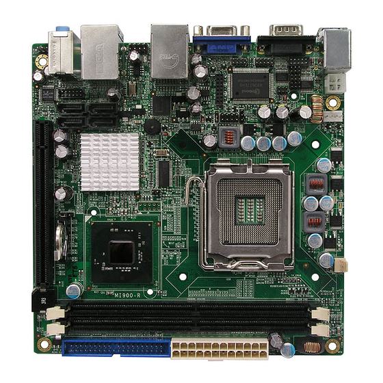
Page 6: Product Description
DVI display interface. LAN functionality is supported with a 10/100 Ethernet controller or with two Gigabit Ethernet controllers. MI900 is expandable for 8x2 pins pin header for adaptor card ID394 that support 2 or 4 serial ports, or ID395 that support TPM 1.2 for security function. -
Page 7: Specifications
Digital IO 4 in and 4 Out LAN Wakeup Other 24 pins ATX main power + 4 pins 12V Power Connector CPU Power: 95W max. System +5V, +3.3V, +12V, -12V & 5VSB Voltage Board Size 170 x 170mm MI900 User’s Manual... -
Page 8: Board Dimensions
INSTALLATIONS Board Dimensions MI900 User’s Manual... -
Page 9: Installations
INSTALLATIONS Installations This section provides information on how to use the jumpers and connectors on the MI900 in order to set up a workable system. The topics covered are: Installing the CPU ................ 6 ATX Power Installation ............... 6 Installing the Memory ..............7 Setting the Jumpers .............. -
Page 10: Installing The Cpu
INSTALLATIONS Installing the CPU The MI900 motherboard supports an LGA 775 processor socket for Intel® Core 2 Duo processors. The LGA 775 processor socket comes with a lever to secure the processor. Refer to the pictures below, from left to right, on how to place the processor into the CPU socket. -
Page 11: Installing The Memory
INSTALLATIONS Installing the Memory The MI900 motherboard supports four DDR2 memory sockets for a maximum total memory of 4GB in DDR memory type. It supports DDR2 533/667/800. Basically, the system memory interface has the following features: Supports two 64-bit wide DDR data channels Available bandwidth up to 6.4GB/s (DDR2 800) for single-channel... -
Page 12: Setting The Jumpers
The following lists the connectors and their respective functions. Jumper Locations on MI900/MI900F ..........9 JBAT1: Clear CMOS Contents ............. 10 JP1, JP2, JP3: RS232/422/485 (COM2) Selection ....... 10 JP6: Processor Setting.............. - Page 13 INSTALLATIONS Jumper Locations on MI900/MI900F Jumper Locations on MI900/MI900F ..........9 JBAT1: Clear CMOS Contents ............ 10 JP1, JP2, JP3: RS232/422/485 (COM2) Selection ....... 10 JP6: Processor Setting ..............10 J6: Power ON Setting ..............11 MI900 User’s Manual...
- Page 14 1-3 & 2-4 JP2: JP2: JP2: 3-5 & 4-6 1-3 & 2-4 1-3 & 2-4 JP6: Processor Setting Setting Processor Used Pin 1-2 Celeron D Short/Closed Core 2 Duo, Pin 1-2 Pentium D, Open Pentium 4 HT MI900 User’s Manual...
- Page 15 INSTALLATIONS J6: Power ON Setting Setting Function Pin 1-2 Power on by system Short/Closed button Pin 2-3 Power on by power Short/Closed supply AC on MI900 User’s Manual...
-
Page 16: Connectors On Mi900
INSTALLATIONS Connectors on MI900 The connectors on MI900 allows you to connect external devices such as keyboard, floppy disk drives, hard disk drives, printers, etc. The following table lists the connectors on MI900 and their respective functions. ATX1: 24-pin ATX Power Connector .............. 14 ATX2: ATX 12V Power Connector .............. - Page 17 INSTALLATIONS Connector Locations on MI900/MI900F ATX1: 24-pin ATX Power Connector ....................14 ATX2: ATX 12V Power Connector ...................... 14 CPU_FAN1: CPU Fan Power Connector ..................... 14 PWR_FAN1: SYSTEM Fan Power Connectors ................... 14 CN2: PS/2 Keyboard and PS/2 Mouse Connectors ................15 CN1 J3: COM1/2 Serial Ports ........................
-
Page 18: Atx1: 24-Pin Atx Power Connector
This connector supplies the CPU operation voltage Pin # Signal Name Ground Ground +12V +12V CPU_FAN1: CPU Fan Power Connector Pin # Signal Name Control Sense +12V Ground PWR_FAN1: SYSTEM Fan Power Connectors Pin # Signal Name Sense +12V Rotation detection MI900 User’s Manual... -
Page 19: Cn2: Ps/2 Keyboard And Ps/2 Mouse Connectors
DTR, Data terminal ready RI, Ring indicator GND, ground Not Used J3: COM2 is jumper selectable for RS-232, RS-422 and RS-485. Pin # Signal Name RS-232 R2-422 RS-485 DATA- DATA+ Ground Ground Ground RTS- RTS+ CTS+ CTS- MI900 User’s Manual... -
Page 20: Vga1: Vga Crt Connector
CN3: Marvell 88E8053 PCI-express Gigabit LAN and USB6/7 Connector CN6: Intel 82562V 10/100 or Intel 82566DC GbE RJ-45 and USB4/5 Connector Note: 10/100 LAN for MI900; DUAL Gigabit LAN for MI900F CN4: Audio Connector CN4 is a 3-jack audio connector MI900 User’s Manual... -
Page 21: F_Usb1: Usb0/Usb1 Connector
Host data 15 Ground Protect pin DRQ0 Ground Host IOW Ground Host IOR Ground IOCHRDY Host ALE DACK0 Ground IRQ14 No connect Address 1 No connect IDE1 Address 0 Address 2 Chip select 0 Chip select 1 Activity Ground MI900 User’s Manual... -
Page 22: J2: Digital I/O Connector (4 In, 4 Out)
ID394 with Fintek F81216, 2 or 4 Serial Ports ID395 Winbond WPCT200 x1 for TPM1.2 J5: Power LED The power LED indicates the status of the main power switch. Pin # Signal Name Power LED No connect Ground MI900 User’s Manual... -
Page 23: J7: System Function Connector
Orientation is not required when making a connection to this header. +5V and 5VSB Signals: Pins 7 and 8 Pin # Signal Name +5VSB PCIE_1: x16 PCI Express Slot MI900 User’s Manual... -
Page 24: Id394 Lpc Serial Ports Adaptor Card
TXD, Transmit data CTS, Clear to send DTR, Data terminal ready RI, Ring indicator GND, ground Not Used CN1: LPC I/F connectors Package list: COM port cable (PK1-20B) x 2 Nylon Nut x 1 Screw x 2 Washer x2 MI900 User’s Manual... -
Page 25: Id395 Winbond Wpct200 For Tpm1.2
INSTALLATIONS ID395 WINBOND WPCT200 for TPM1.2 CN1: LPC I/F connectors Package list Nylon Nut x 1 Screw x 2 Washer x2 MI900 User’s Manual... - Page 26 INSTALLATIONS This page is intentionally left blank. MI900 User’s Manual...
-
Page 27: Bios Setup
Frequency/Voltage Control ............40 Load Fail-Safe Defaults ..............41 Load Optimized Defaults ............. 41 Set Supervisor/User Password ............41 Save & Exit Setup ................ 41 Exit Without Saving ..............41 2nd SuperIO Device ..............42 Security Chip Configuration............43 MI900 User’s Manual... -
Page 28: Bios Introduction
<PgUp> and <PgDn> keys to change entries, <F1> for help and <Esc> to quit. When you enter the Setup utility, the Main Menu screen will appear on the screen. The Main Menu allows you to select from various setup functions and exit choices. MI900 User’s Manual... - Page 29 These defaults have been carefully chosen by both Award and your system manufacturer to provide the absolute maximum performance and reliability. Changing the defaults could cause the system to become unstable and crash in some cases. MI900 User’s Manual...
-
Page 30: Standard Cmos Setup
The following describes each item of this menu. Date The date format is: Day : Sun to Sat Month : 1 to 12 Date : 1 to 31 Year : 1999 to 2099 MI900 User’s Manual... - Page 31 Precomp : Write precompensation Landing Zone : Landing zone Sector : Number of sectors The Access Mode selections are as follows: (HD < 528MB) (HD > 528MB and supports Logical Block Addressing) Large (for MS-DOS only) Auto MI900 User’s Manual...
- Page 32 The system boot will not be halted for a disk error; it will stop for all other errors. All, But Disk/Key The system boot will not be halted for a key- board or disk error; it will stop for all others. MI900 User’s Manual...
-
Page 33: Advanced Bios Features
When the CPU requests data, the system transfers the requested data from the main DRAM into cache memory, for even faster access by the CPU. These items allow you to enable (speed up memory access) or disable the cache function. By default, these items are Enabled. MI900 User’s Manual... - Page 34 Settings are from 6 to 30 characters per second. Typematic Delay (Msec) When the typematic rate is enabled, this item allows you to set the time interval for displaying the first and second characters. By default, this item is set to 250msec. MI900 User’s Manual...
- Page 35 OS/2 that depends on certain BIOS calls to access memory. The default setting is Non-OS/2. Small Logo (EPA) Show The EPA logo appears at the right side of the monitor screen when the system is boot up. The default setting is Disabled. MI900 User’s Manual...
-
Page 36: Advanced Chipset Features
16 MB. The choices are Enabled and Disabled. On-Chip VGA Setting The fields under the On-Chip VGA Setting and their default settings are: PEG/On Chip VGA Control: Auto On-Chip Frame Buffer Size: 8MB DVMT Mode: DVMT DVMT/Fixed Memory Size: 128MB MI900 User’s Manual... -
Page 37: Integrated Peripherals
Phoenix - AwardBIOS CMOS Setup Utility USB Device Setting Enabled ITEM HELP USB 1.0 Controller Enabled Menu Level > USB 2.0 Controller Enabled USB Keyboard Function Enabled USB Mouse Function USB Storage Function Enabled *** USB Mass Storage Device Boot Setting *** MI900 User’s Manual... - Page 38 Power ON Function This field is related to how the system is powered on – such as with the use of conventional power button, keyboard or hot keys. The default is BUTTON ONLY. MI900 User’s Manual...
- Page 39 Enabled. In order to use USB 2.0, necessary OS drivers must be installed first. Please update your system to Windows 2000 SP4 or Windows XP SP2. USB Keyboard/Mouse/Storage Function The options for this field are Enabled and Disabled. By default, this field is set to Disabled. MI900 User’s Manual...
-
Page 40: Power Management Setup
This field defines the Video Off features. There are three options. V/H SYNC + Blank Default setting, blank the screen and turn off vertical and horizontal scanning. DPMS Allows BIOS to control the video display. Blank Screen Writes blanks to the video buffer. MI900 User’s Manual... - Page 41 When an I/O device wants to gain the attention of the operating system, it signals this by causing an IRQ to occur. When the operating system is ready to respond to the request, it interrupts itself and performs the service. MI900 User’s Manual...
-
Page 42: Init Display First
MPEG ISA/VESA VGA card. When this field is disabled, a PCI/VGA cannot work with an MPEG ISA/VESA card. Maximum Payload Size The default setting of the PCI Express Maximum Payload Size is 128. MI900 User’s Manual... -
Page 43: Pc Health Status
This function can help prevent damage to the system that is caused by overheating. Temperatures/Fan Speeds/Voltages These fields are the parameters of the hardware monitoring function feature of the board. The values are read-only values as monitored by the system and show the PC health status. MI900 User’s Manual... -
Page 44: Auto Detect Pci Clk
Auto Detect PCI Clk This field enables or disables the auto detection of the PCI clock. Spread Spectrum This field sets the value of the spread spectrum. The default setting is Disabled. This field is for CE testing use only MI900 User’s Manual... -
Page 45: Load Fail-Safe Defaults
Select this option to exit the Setup utility without saving the changes you have made in this session. Typing “Y” will quit the Setup utility without saving the modifications. Typing “N” will return you to Setup utility. MI900 User’s Manual... -
Page 46: Onboard Serial Port
These fields allow you to select the onboard serial and parallel ports and their addresses. The default values for these ports are: Serial Port 3 230/IRQ5 Serial Port 4 238/IRQ7 Serial Port 5 Disabled/IRQ10 Serial Port 6 Disabled/IRQ11 MI900 User’s Manual... -
Page 47: Security Chip Configuration
Menu Level > X TPM Status No Change Enable/Disable Trusted Platform Module TPM Support The default setting is Disabled. TPM Current Status The default setting is Disabled & Deactivated. TPM Status The default setting is No change. MI900 User’s Manual... - Page 48 BIOS SETUP This page is intentionally left blank. MI900 User’s Manual...
-
Page 49: Drivers Installation
Realtek Codec Audio Driver Installation ......50 Intel LAN Drivers Installation .......... 51 IMPORTANT NOTE: After installing your Windows operating system (Windows 2000/XP), you must install first the Intel Chipset Software Installation Utility before proceeding with the drivers installation. MI900 User’s Manual... -
Page 50: Intel Q965 Chipset Software Installation Utility
Installation Utility,Please update your system to Windows 2000 SP4 or Windows XP SP1A) 1. Insert the CD that comes with the board and the screen below would appear. Click Intel (R) Q965 Chipset Drivers, then Intel(R) Chipset Software Installation Utility. MI900 User’s Manual... - Page 51 3. Click Yes to accept the software license agreement and proceed with the installation process. 4. On the Readme Information screen, click Next to continue the installation. 5. The Setup process is now complete. Click Finish to restart the computer and for changes to take effect. MI900 User’s Manual...
-
Page 52: Intel Q965 Chipset Graphics Driver
1. Insert the CD that comes with the board and the screen below would appear. Click Intel (R) Q965 Chipset Drivers, then Intel (R) Q965 Chipset Family Graphics Driver. 2. When the Welcome screen appears, click Next to continue. MI900 User’s Manual... - Page 53 4. On Readme File Information screen, click Next to continue. 5. On Setup Progress screen, click Next to continue the installation. 6. The Setup process is now complete. Click Finish to restart the computer and for changes to take effect. MI900 User’s Manual...
-
Page 54: Realtek Codec Audio Driver Installation
Click Intel (R) Q965 Chipset Drivers, then Realtek High Definition Codec Audio Driver. 2. When the Welcome screen appears, click Next to continue. 3. The Setup process is now complete. Restart the computer when prompted for changes to take effect. MI900 User’s Manual... -
Page 55: Intel Lan Drivers Installation
1. Insert the CD that comes with the board. On the initial screen, Click Intel (R) Q965 Chipset Drivers, then Intel(R) PRO LAN Network Drivers. 2. On the next screen, click Install Drivers to start the drivers installation. MI900 User’s Manual... - Page 56 5. When the Setup Type appears, click Complete and Next to continue. 6. When the Ready to Install the Program screen appears, click Install to continue. 7. The Setup process is now complete (InstallShield Wizard Completed). Click Finish to restart the computer and for changes to take effect. MI900 User’s Manual...
- Page 57 3. Click Next to agree with the license agreement. 4. Click Next when the Readme Information screen appears to proceed with the drives installation process. 5. When the Installation is complete, click Finish for the changes to take effect. MI900 User’s Manual...
-
Page 58: Appendix
Parallel Port #1(LPT1) 360h - 36Fh Network Ports 3B0h - 3BFh Monochrome & Printer adapter 3C0h - 3CFh EGA adapter 3D0h - 3DFh CGA adapter 3F0h - 3F7h Floppy Disk Controller 3F8h - 3FFh Serial Port #1(COM1) MI900 User’s Manual... -
Page 59: Interrupt Request Lines (Irq)
Serial Port #2 IRQ4 Serial Port #1 IRQ5 Reserved IRQ6 Floppy Disk Controller IRQ7 Parallel Port #1 IRQ8 Real Time Clock IRQ9 Reserved IRQ10 Reserved IRQ11 Reserved IRQ12 PS/2 Mouse IRQ13 80287 IRQ14 Primary IDE IRQ15 Secondary IDE MI900 User’s Manual... -
Page 60: Watchdog Timer Configuration
**endptr; copyright(); if (argc != 2) printf(" Parameter incorrect!!\n"); return 1; if (Init_W627EHF() == 0) printf(" Winbond 83627HF is not detected, program abort.\n"); return 1; bTime = strtol (argv[1], endptr, 10); MI900 User’s Manual... - Page 61 = Get_W627EHF_Reg( 0xF5); bBuf &= (!0x08); Set_W627EHF_Reg( 0xF5, bBuf); //count mode is second Set_W627EHF_Reg( 0xF6, interval); //set timer //======================================================================= void DisableWDT(void) Set_W627EHF_LD(0x08); //switch to logic device 8 Set_W627EHF_Reg(0xF6, 0x00); //clear watchdog timer Set_W627EHF_Reg(0x30, 0x00); //watchdog disabled //======================================================================= MI900 User’s Manual...
- Page 62 Init_Finish; } W627EHF_BASE = 0x00; result = W627EHF_BASE; Init_Finish: return (result); //======================================================================= void Unlock_W627EHF (void) outportb(W627EHF_INDEX_PORT, W627EHF_UNLOCK); outportb(W627EHF_INDEX_PORT, W627EHF_UNLOCK); //======================================================================= ==== void Lock_W627EHF (void) outportb(W627EHF_INDEX_PORT, W627EHF_LOCK); //======================================================================= void Set_W627EHF_LD( unsigned char LD) Unlock_W627EHF(); outportb(W627EHF_INDEX_PORT, W627EHF_REG_LD); outportb(W627EHF_DATA_PORT, LD); MI900 User’s Manual...
- Page 63 (W627EHF_BASE) #define W627EHF_DATA_PORT (W627EHF_BASE+1) //======================================================================= #define W627EHF_REG_LD 0x07 //======================================================================= #define W627EHF_UNLOCK 0x87 #define W627EHF_LOCK 0xAA //======================================================================= unsigned int Init_W627EHF(void); void Set_W627EHF_LD( unsigned char); void Set_W627EHF_Reg( unsigned char, unsigned char); unsigned char Get_W627EHF_Reg( unsigned char); //======================================================================= #endif //__W627EHF_H MI900 User’s Manual...
- Page 64 Set_W627HF_Reg(0xF1, ((ucDO & 0x0F) << 4)); ucBuf = Get_W627HF_Reg(0xF1) & 0x0F; if (ucBuf != ucDI) ucDI = ucBuf; printf("Digital I/O Input Changed. Current Data is 0x%X\n",ucDI); if (kbhit()) getch(); break; delay(500); return 0; //===================================================================== void ClrKbBuf(void) while(kbhit()) getch(); //--------------------------------------------------------------------------- MI900 User’s Manual...
Need help?
Do you have a question about the MI900 and is the answer not in the manual?
Questions and answers