
Related Manuals for IBASE Technology MI989 Series


Summary of Contents for IBASE Technology MI989 Series
- Page 1 MI989 Series AMD V2000™ Mini-ITX Motherboard User’s Manual Version 1.0 (June 2021)
- Page 2 No part of this publication may be reproduced, copied, stored in a retrieval system, translated into any language or transmitted in any form or by any means, electronic, mechanical, photocopying, or otherwise, without the prior written consent of IBASE Technology, Inc. (hereinafter referred to as “IBASE”). Disclaimer IBASE reserves the right to make changes and improvements to the products described in this document without prior notice.
- Page 3 Compliance This is a class B product. In a domestic environment, this product may cause radio interference in which case users may be required to take adequate measures. This product has been tested and found to comply with the limits for a Class B device, pursuant to Part 15 of the FCC Rules.
- Page 4 Important Safety Information Carefully read the precautions before using the board. Environmental conditions: Use this product in environments with ambient temperatures between 0˚C and 60˚C. Do not leave this product in an environment where the storage temperature may be below -20° C or above 70° C. To prevent from damages, the product must be used in a controlled environment.
- Page 5 Warranty Policy IBASE standard products: 24-month (2-year) warranty from the date of shipment. If the date of shipment cannot be ascertained, the product serial numbers can be used to determine the approximate shipping date. -party parts: 12-month (1-year) warranty from delivery for the 3 -party parts that are not manufactured by IBASE, such as CPU, CPU cooler, memory, storage devices, power adapter, panel and touchscreen.
-
Page 6: Table Of Contents
Table of Contents Chapter 1 General Information ..........1 Introduction ..................2 Features ....................2 Packing List ..................3 Optional Accessories ................3 Specifications ..................4 Block Diagram ..................6 Overview ..................... 7 Dimensions ..................9 Chapter 2 Hardware Configuration ......... 11 Installations .................. -
Page 7: Chapter 1 General Information
Chapter 1 General Information The information provided in this chapter includes: Features Packing List Specifications Block Diagram Board Overview Board Dimensions... -
Page 8: Introduction
Introduction AMD Ryzen™ V2000-series MI989F is a mini-ITX motherboard based on processor. The integrated graphics device on the AMD Ryzen V2000-series processor integrated graphics drives four DisplayPort interfaces. Flexible I/O connections are provided by two GbE, four USB 3.1, two USB 2.0, four COM, and two SATA III, as well as three M.2 sockets (M2280, E2230 &... -
Page 9: Packing List
General Information Packing List Your MI989F package should include the items listed below. If any of the items below is missing, contact the distributor or dealer from whom you purchased the product. MI989F Motherboard I/O Shield SATA Cable (SATA-3F) ... -
Page 10: Specifications
Specifications Model Name MI989F-2748 MI989F-2718 Form Factor Mini-ITX System Windows 10 Operating System Linux Ubuntu CPU Type AMD Ryzen™ V2748 AMD Ryzen™ V2718 CPU Speed 2.9 GHz / 4.15 GHz 1.7 GHz / 4.15 GHz Cache 8MB / L3; 4MB / L2 8MB / L3;... - Page 11 General Information 4 x DisplayPort (1.4) 3840 x 2160 at 60 Hz Display (depend by AMD support) 2 x RJ45 GbE 2 x USB 3.1: I/O coastline connectors 2 x USB 2.0: I/O coastline connectors 2 x USB 2.0: via an on-board pin headers 4 x COM ports: ...
-
Page 12: Block Diagram
Block Diagram MI989 User’s Manual... -
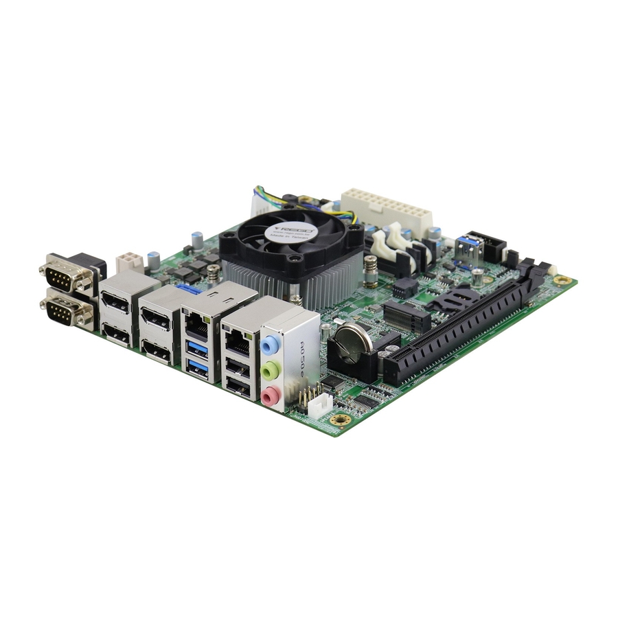
Page 13: Overview
General Information Overview Top View *The photos above are for reference only. Some minor components may differ. MI989 User’s Manual... - Page 14 I/O View Name Name COM1 Port 2 USB 3.1 Ports COM2 Port 2 USB 2.0 Ports DisplayPort 0/1 Audio Line-In DisplayPort 2/3 Audio Line-Out LAN Ports Microphone-In MI989 User’s Manual...
-
Page 15: Dimensions
General Information Dimensions MI989 User’s Manual... - Page 16 This page is intentionally left blank. MI989 User’s Manual...
-
Page 17: Chapter 2 Hardware Configuration
Chapter 2 Hardware Configuration This section provides information on jumper settings and connectors on the MI989F in order to set up a workable system. On top of that, you will also need to install crucial pieces such as the CPU and the memory before using the product. -
Page 18: Installations
Installations 2.1.1 Installing the Memory To install the modules, locate the memory slot on the board and perform the following steps: Press the ejector tabs of the memory slot down and outwards with your fingertips. Hold the meomry module and align the key of the module with that on the memory slot. -
Page 19: Setting The Jumpers
Hardware Configuration Setting the Jumpers Set up and configure your MI989F by using jumpers for various settings and features according to your needs and applications. Contact your supplier if you have doubts about the best configuration for your use. 2.2.1 How to Set Jumpers Jumpers are short-length conductors consisting of several metal pins with a non-conductive base mounted on the circuit board. -
Page 20: Jumper & Connector Locations On Mi989
Jumper & Connector Locations on MI989 MI989 User’s Manual... -
Page 21: Jumpers Quick Reference
Hardware Configuration Jumpers Quick Reference Function Jumper Name Page CCTALK Power Selection Clearing CMOS Data JBAT1 2.4.1 CCTALK Power Selection (JP1) Function Pin closed Illustration (default) MI989 User’s Manual... - Page 22 2.4.2 Clear CMOS Data (JBAT1) Function Pin closed Illustration Normal (default) Clear CMOS MI989 User’s Manual...
-
Page 23: Connectors Quick Reference
Hardware Configuration Connectors Quick Reference Function Connector Name Page COM1 & COM2 Ports COM3 & COM4 RS-232 Ports J7 (COM3), J9 (COM4) COM6 (CCTALK) Ports COM5 (TTL) Ports Digital I/O Connector ATX Power Connector ATX1 ATX 12V Power Connector ATX2 Dual USB 2.0 Connector Front Panel Audio Connector Audio Amplifier Connector... - Page 24 2.5.1 COM1 & COM2 RS-232/422/485 Ports (CN8) COM1: COM2: Signal Name Signal Name DCD, Data carrier detect DSR, Data set ready RXD, Receive data RTS, Request to send TXD, Transmit data CTS, Clear to send DTR, Data terminal RI, Ring indicator ready Ground Signal Name...
- Page 25 Hardware Configuration 2.5.2 COM3 & COM4 RS-232 Ports (J7, J9) Signal Name Signal Name DCD, Data carrier detect RXD, Receive data DTR, Data terminal TXD, Transmit data ready Ground DSR, Data set ready RTS, Request to send CTS, Clear to send RI, Ring indicator MI989 User’s Manual...
- Page 26 2.5.3 COM6 (CCTALK) Ports (J3) Assignment Assignment Ground CCTALK DATA 2.5.4 COM5 (TTL Level) Ports (J4) Signal Name Signal Name DCD (TTL) RXD (TTL) TXD (TTL) DTR (TTL) Ground DSR (TTL) RTS (TTL) CTS (TTL) RI (TTL) MI989 User’s Manual...
- Page 27 Hardware Configuration 2.5.5 Digital I/O Connector (J5) Signal Name Signal Name Ground OUT3 OUT1 OUT2 OUT0 MI989 User’s Manual...
- Page 28 2.5.6 ATX Power Connector (ATX1) Signal Name Signal Name 3.3V 3.3V 3.3V -12V Ground Ground PS-ON Ground Ground Ground Ground Ground Power good 5VSB +12V +12V 3.3V Ground MI989 User’s Manual...
- Page 29 Hardware Configuration 2.5.7 ATX 12V Power Connector (ATX2) Signal Name Signal Name Ground +12V Ground +12V 2.5.8 Dual USB 2.0 Connector (J12) Signal Name Signal Name Ground Ground MI989 User’s Manual...
- Page 30 2.5.9 Front Panel Audio Connector (J13) Signal Name Signal Name MIC IN_L Ground MIC IN_R LINE_R Ground Sense LINE_L Ground 2.5.10 Amplifier Connector (J14) Assignment Assignment SPK_L+ SPK_R- SPK_L- SPK_R+ MI989 User’s Manual...
- Page 31 Hardware Configuration 2.5.11 Front Panel Settings Connector (J2) Signal Name Signal Name Power BTN Power BTN HDD LED+ HDD LED- Reset BTN Reset BTN Power LED+ Power LED- J18 is utilized for system indicators to provide light indication of the computer activities and switches to change the computer status.
- Page 32 2.5.13 CPU Fan Power Connector (CPU_FAN1) Signal Name Signal Name Ground Rotation detection +12V Control MI989 User’s Manual...
- Page 33 Hardware Configuration 2.5.14 System Fan Power Connector (SYS_FAN1, SYS_FAN2) Signal Name Signal Name Ground Rotation detection +12V Control MI989 User’s Manual...
- Page 34 This page is intentionally left blank. MI989 User’s Manual...
-
Page 35: Chapter 3 Drivers Installation
Chapter 3 Drivers Installation This chapter introduces installation of the following drivers: - AMD Ryzen V2000 Chipset Drivers - AMD Ryzen V2000 Graphics Drivers - Realtek High Definition Audio Driver - LAN Driver Installation... -
Page 36: Introduction
Introduction This section describes the installation procedures for software and drivers. The software and drivers are included with the motherboard. AMD Ryzen V2000 Chipset Drivers Installation Insert the disk enclosed in the package with the board. Click AMD on the left pane and then AMD Ryzen V2000 Drivers on the right pane. Click AMD Ryzen V2000 Graphics Drivers. - Page 37 Driver Installation Click Install to install the software. When the AMD Chipset Software has bee installed successfully, click Close. MI989 User’s Manual...
-
Page 38: Amd Ryzen V2000 Graphics Drivers Installation
AMD Ryzen V2000 Graphics Drivers Installation Click AMD on the left pane and then AMD Ryzen V2000 Graphics Drivers on the right pane. Click Install to agree to all the terms and conditions stated in the Radeon Software End User License Agreement, and install the software. - Page 39 Driver Installation Installing AMD Display Drivers. Click Restart as recommended in order to complete installation. MI989 User’s Manual...
-
Page 40: Realtek High Definition Audio Driver Installation
Realtek High Definition Audio Driver Installation Click AMD on the left pane and then Realtek High Definition Audio Driver on the right pane. On the Welcome screen of the InstallShield Wizard, click Next. When the driver has been successfully installed, restart the computer. MI989 User’s Manual... -
Page 41: Lan Driver Installation
Driver Installation LAN Driver Installation Click LAN Card on the left pane and then Intel LAN Controller Drivers on the right pane. Click Intel(R) I21x Gigabit Networks Drivers. When the Welcome screen appears, click Next. MI989 User’s Manual... - Page 42 Accept the license agreement and click Next. On the Setup Options screen, tick the checkbox to select the desired driver(s) for installation. Then click Next to continue. The wizard is ready to begin installation. Click Install. When installation is complete, click Finish. MI989 User’s Manual...
-
Page 43: Chapter 4 Bios Setup
Chapter 4 BIOS Setup This chapter describes the different settings available in the AMI BIOS that comes with the board. The topics covered in this chapter are as follows: Main Settings Advanced Settings Chipset Settings Boot Settings ... -
Page 44: Introduction
4.1 Introduction The BIOS (Basic Input/Output System) installed in the ROM of your computer system supports AMD APU. The BIOS provides critical low-level support for standard devices such as disk drives, serial ports and parallel ports. It also provides password protection as well as special support for detailed fine-tuning of the chipset controlling the entire system. -
Page 45: Main Settings
BIOS Setup 4.3 Main Settings BIOS Setting Description Sets the date. Use the <Tab> key to switch System Date between the data elements. Set the time. Use the <Tab> key to switch System Time between the data elements. 4.4 Advanced Settings This section allows you to configure, improve your system and allows you to set up some system features according to your preference. - Page 46 4.4.1 M.2 B-Key Control Setting BIOS Setting Description M.2 B-Key Control The options are: SATA, PCIE and AUTO 4.4.2 ACPI Settings BIOS Setting Description Enables / Disables BIOS support for security Security Device device. OS will not show security device. TCG Support EFI protocol and INTIA interface will not be available.
- Page 47 BIOS Setup BIOS Setting Description SHA256 PCR Bank Enables / Disables SHA256 PCR Bank. Schedule an operation for the security device. Pending operation Note: Your computer will reboot during restart in order to change state of security device. Platform Hierarchy Enables / Disables platform hierarchy.
- Page 48 4.4.3 ACPI Settings BIOS Setting Description Enable ACPI Auto Enables / Disables BIOS ACPI auto Configuration configuration. Enable Hibernation Enables / Disables the system ability to hibernate (OS/S4 Sleep State). This option may be not effective with some OS. ACPI Sleep State Selects an ACPI sleep state where the system will enter when the Suspend button is pressed.
- Page 49 BIOS Setup Serial Port 1 Configuration Serial Port 2 Configuration MI989 User’s Manual...
- Page 50 Serial Port 3 Configuration Serial Port 4 Configuration Serial Port 5 Configuration Serial Port 6 Configuration MI989 User’s Manual...
- Page 51 BIOS Setup 4.4.5 Hardware Monitor BIOS Setting Description Enables / Disables the CPU smart fan feature. CPU Fan Smart Fan Options: Disabled / 50 °C / 60 °C / 70 °C / 80 Control °C Enables / Disables the system smart fan feature.
- Page 52 4.4.6 CPU Configuration MI989 User’s Manual...
- Page 53 BIOS Setup 4.4.7 IDE Configuration MI989 User’s Manual...
- Page 54 4.4.8 AMI Graphic Output Protocol Policy BIOS Setting Description Output Select Allows you to select an output interface. MI989 User’s Manual...
- Page 55 BIOS Setup 4.4.9 USB Configuration BIOS Setting Description Enables Legacy USB support. Auto disables legacy support if there is no Legacy USB Support USB device connected. Disable keeps USB devices available only for EFI applications. This is a workaround for OSes without XHCI XHCI Hand-off hand-off support.
- Page 56 4.4.10 Network Stack Configuration BIOS Setting Description Network Stack Enable/Disable UEFI Network Stack Enable/Disable IPv4 PXE boot support. If IPv4 PXE Support disabled, IPv4 PXE boot support will not be available Enable/Disable IPv4 HTTP boot support. If IPv4 HTTP Support disabled, IPv4 HTTP boot support will not be available Enable/Disable IPv6 HTTP boot support.
- Page 57 BIOS Setup 4.4.12 NVMe Configuration MI989 User’s Manual...
- Page 58 4.4.13 AMD CBS MI989 User’s Manual...
-
Page 59: Chipset Settings
BIOS Setup 4.5 Chipset Settings 4.5.1 SB USB Configuration BIOS Setting Description Options for SB USB Configuration. SB USB Configuration 4.5.1.1. XHCI Ports BIOS Setting Description XHCI 0 & XHCI 1 Enables / Disables the XHCI0 & XHCI1 ports Ports (XHCI/EMCI). - Page 60 4.5.2 North Bridge Configuration MI989 User’s Manual...
-
Page 61: Security Settings
BIOS Setup 4.6 Security Settings BIOS Setting Description Administrator Sets an administrator password for the setup Password utility. User Password Sets a user password. HDD Security HDD Security Configuration for selected drive Configuration Secure Boot Secure Boot Configuration BIOS Setting Description Secure Boot feature is active if Secure Boot enabled. -
Page 62: Boot Settings
BIOS Setting Description Secure Boot mode options: Standard or Custom. Secure Boot Mode In Custom mode, Secure Boot Policy variables can be configured by a physically present user without full authentication. Force System to User Mode. Install factory Restore Factory Keys default Secure Boot key databases. -
Page 63: Save & Exit Settings
BIOS Setup 4.8 Save & Exit Settings BIOS Setting Description Save Changes and Exits system setup after saving the changes. Exit Discard Changes Exits system setup without saving any and Exit changes. Save Changes and Resets the system after saving the changes. Reset Discard Changes Resets system setup without saving any... - Page 64 This page is intentionally left blank. MI989 User’s Manual...
-
Page 65: Appendix
Appendix This section provides the mapping addresses of peripheral devices, the sample code of watchdog timer configuration, and types of on-board connectors. -
Page 66: I/O Port Address Map
I/O Port Address Map Each peripheral device in the system is assigned a set of I/O port addresses which also becomes the identity of the device. The following table lists the I/O port addresses used. Address Device Description 0x00000A00-0x00000A0F Motherboard resources 0x00000A10-0x00000A1F Motherboard resources 0x00000E80-0x00000E8F... - Page 67 Appendix Address Device Description 0x00000088-0x00000088 Motherboard resources 0x0000008C-0x0000008E Motherboard resources 0x00000090-0x0000009F Motherboard resources 0x000000A2-0x000000BF Motherboard resources 0x000000B1-0x000000B1 Motherboard resources 0x000000E0-0x000000EF Motherboard resources 0x000004D0-0x000004D1 Motherboard resources 0x0000040B-0x0000040B Motherboard resources 0x000004D6-0x000004D6 Motherboard resources 0x00000C00-0x00000C01 Motherboard resources 0x00000C14-0x00000C14 Motherboard resources 0x00000C50-0x00000C51 Motherboard resources 0x00000C52-0x00000C52 Motherboard resources 0x00000C6C-0x00000C6C...
-
Page 68: Interrupt Request Lines (Irq)
Interrupt Request Lines (IRQ) Peripheral devices use interrupt request lines to notify CPU for the service required. The following table shows the IRQ used by the devices on board. Level Function IRQ 0 High precision event timer IRQ 0 System timer IRQ 8 High precision event timer IRQ 7... - Page 69 Appendix Level Function IRQ 54~204 Microsoft ACPI-Compliant System IRQ 256~511 Microsoft ACPI-Compliant System IRQ 1024 Trusted Platform Module 2.0 IRQ 37 AMD Sensor Fusion Hub IRQ 36 High Definition Audio Controller IRQ 4294967291 PCI Express Root Port IRQ 4294967290 PCI Express Root Port IRQ 4294967294 PCI Express Root Port IRQ 4294967293...
-
Page 70: Onboard Connector Types
Onboard Connector Types Compatible Mating Function Connector Onboard Type Type for Reference COM3 & COM4 J7 (COM3), Hao Guo Xing Ye HRS DF11-10DS-2C RS-232 Ports J9 (COM4) DF11-10S-PA66H E-CALL BOX E-CALL COM5 (TTL) J4 (COM5) HEADER 2.5mm Ports 0109-042-XX0 0151-2011009 K10 E-CALL MINI BASE COM6...
Need help?
Do you have a question about the MI989 Series and is the answer not in the manual?
Questions and answers