Table of Contents
Advertisement
Quick Links
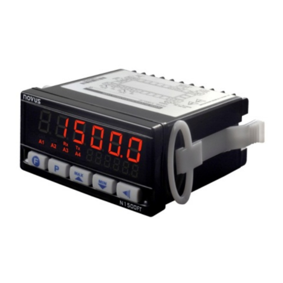
N1500FT Indicator
FLOW RATE INDICATOR – INSTRUCTIONS MANUAL – V1.0x A
SAFETY ALERTS
The symbols below are used on the equipment and throughout this
document to draw the user's attention to important operational and
CAUTION:
Read this manual carefully prior to
Installation and operation of the
unit.
All safety related instructions that appear in the manual must be
observed to ensure personal safety and to prevent damage to either
the instrument or the system. If the device is used in a manner not
specified in this manual, its safety features may be impaired.
INTRODUCTION
This
flow
rate
indicator
provides
retransmission, alarm and RS485 communication features (optional
RTU Modbus slave). It reads most flow signals available in the
market, such as pulse, magnetic pickup and 4-20 mA. The pulse
input allows connecting sensors with outputs such as reed-switch,
NPN, PNP and tension. Both for pulse input and 4-20 mA input, unit
is selectable and a scale factor is set to turn the input signal into the
unit of choice. It provides an isolated pulse output for totalized flow
retransmission and a 4-20 mA output for immediate flow
retransmission. Alarms are set off through 2 to 4 relays, depending
on the equipment model.
AC models provide a 24 Vdc / 50 mA output.
INPUTS
The flow rate indicator allows for two basic input types:
• Instantaneous flow input through a 4-20 mA signal. In this case,
flow totalization is obtained by integrating instantaneous flow rate.
• Totalized flow input through a pulse signal. In this case,
instantaneous flow rate is obtained by deriving totalized flow rate.
Pulse signals may come from sensors/transmitters with NPN, PNP, dry
contact (reed switch) and tension signal output, or even magnetic
pickup outputs.
When the input is set to 4-20 mA, you should establish on screens
InLL and InKL which flow values are equivalent to 4 and 20 mA.
When the 4-20 mA input is not used as flow input, it may be used
alternatively as auxiliary input. This way it is possible to measure the
pressure of a pipeline, for instance.
The pulse flow input may be scaled, both for instantaneous and
totalized flow rates (independently), through 'k' multiplication factors:
k.1nst and k.tot.
Both flow time base and unit must be defined on screen Un1t
To do so, there are six characters, the first five of which are used to
set the unit and the last one (to the right) is used to set the time base
on which the flow rate is measured. Available time bases are 's'
(seconds), 'm' (minutes), 'h' (hours) and 'd' (days).
NOVUS AUTOMATION
CAUTION OR DANGER:
Electric shock hazard
indication,
totalization,
1.
With pulse flow input, totalization will continue even if the input rate is
below the minimum rate required. Instantaneous flow rate indication
will be zero whenever there is a time lapse of 10 seconds without
input variation. In this case, whenever there is a totalization increase
(more input pulses), the instantaneous flow value will be shown for
the nest 10 seconds.
CUSTOMIZED LINEARIZATION
When the flow rate is read through a 4-20 mA input, it is possible to
apply a customized linearization composed of 30 input points and 30
output points. Whenever the reading falls between two input points, it
will be normalized to the range defined by the respective points in the
output range.
The search for framing the value read is done while the list of input
points is incrementally declared. The search is terminated if the next
point in the list is lower than the current one. If the input value is
lower than the first value in the list of input points, linearization will
return the first output value. Similarly, if the input value is greater
than the highest value in the list of input points, linearization will
return the highest value in the output list.
IMPORTANT: At least two pairs of input-output points are required
for adequate customized linearization.
RETRANSMISSION
Flow rate retransmission can be done via 4-20 mA output and pulse
output.
The 4-20 mA output may be used regardless of the type of flow input.
To use it, just set the retransmission range to RTLL and RTKL,
associating the flow rates to 4 and 20 mA.
In the case of retransmission via pulse output, one must choose
between volumetric pulse output and frequency pulse output. The
former may be used regardless of the type of input, while the latter is
available only for pulse inputs.
In the volumetric mode, a pulse of configurable length is generated
every time the totalizer accumulates a preset volume. For example,
for a period of 1 second and volume of 10 liters, a 1-second pulse will
be generated for every 10 liters totalized.
In the frequency mode, the pulse output will divide the input
frequency by a programmable constant whose value is equal to or
higher than 2.
IMPORTANT: Maximum output frequency has hardware limitation.
See Specifications.
ALARMS
The indicator's basic version has 2 alarm outputs, with the option of
up to 4 alarms. Whenever an alarm is on, a corresponding light
signal will be displayed on the front panel.
ALARM FUNCTIONS
The alarms can be programmed to operate with four different
functions, described below. They may also be turned off.
Alarms use only the instantaneous flow rate reading. Totalization
readings cannot be used as input for alarms. The auxiliary 4-20 mA
input (when it is not being used for flow rate measurement) may be
used only as input for the open sensor alarm.
1/8
Advertisement
Table of Contents

Related Manuals for Novus N1500FT


Summary of Contents for Novus N1500FT
- Page 1 N1500FT Indicator FLOW RATE INDICATOR – INSTRUCTIONS MANUAL – V1.0x A SAFETY ALERTS With pulse flow input, totalization will continue even if the input rate is below the minimum rate required. Instantaneous flow rate indication The symbols below are used on the equipment and throughout this will be zero whenever there is a time lapse of 10 seconds without document to draw the user’s attention to important operational and...
- Page 2 N1500FT Flow Indicator • Open Sensor – I. e rror FEEDER The open sensor alarm operates whenever the input sensor is badly The feeder function is used to control the volume of fluids based on connected or broken. Valid only for 4-20 mA inputs.
- Page 3 N1500FT Flow Indicator CONNECTIONS FOR INPUT AND OUTPUT SIGNALS A1, A2, A3 and A4 Indicators: They show the alarms that are on. Key: “Function” key, whose operation is user selectable. It is important that these connections are well made, with signal or sensor wires securely attached to rear panel terminals.
- Page 4 N1500FT Flow Indicator PROGRAMMING THE INDICATOR Selection of Function Alarm 4: off, 1.Error, Fva4 Lo, x1 and FEEDER. Function Alarm 4 MAIN CYCLE Visible only for the 4 relays model. xya4 The first screen of the main cycle can be 888888 programmed in the Main screen.
- Page 5 N1500FT Flow Indicator For screens that show totalizations, whether it is the total or the SELECTION OF FLOW INPUT TYPE non-resettable value, when the reading cannot be shown in six SENSOR DESCRIPTION digits it will be shown in two halves; that is, the lower six digits and the higher five digits (preceded by a k.
- Page 6 N1500FT Flow Indicator CUSTOMIZED LINEARIZATION CYCLE On this screen, whenever you press ovx( , a standard current close to 20 mA will Output High Lin.enbl Enables linearization. Applicable only when be applied. Measure current, in mA, and enter Calibration Linearization flow input is 4-20 mA.
- Page 7 N1500FT Flow Indicator • Maximum connection distance: 1000 meters. MESSAGE PROBLEM DESCRIPTION • Selectable speed; 8 bits of data; 1 stop bit; selectable parity (no Value reading is above limits allowed for this VVVVV parity, even or odd). sensor or signal.
-
Page 8: Specifications
............Accuracy: ± 30 ppm @ 25 °C Magnetic Pickup: ... Frequency: 0.1 to 8000 Hz @ 30 mVpp NOVUS warrants to the original purchaser that this product is free from ............0.1 to 50000 Hz @ 250 mVpp defects in material and workmanship under normal use and service ..........
Need help?
Do you have a question about the N1500FT and is the answer not in the manual?
Questions and answers