Table of Contents
Advertisement
Quick Links
Advertisement
Table of Contents

Related Manuals for Novus N1540


Summary of Contents for Novus N1540
- Page 1 N1540 DIGITAL PANEL METER USER GUIDE V2.1x G...
-
Page 2: Table Of Contents
COMMUNICATION INTERFACE ..............................18 12.1.1 RS485 INTERFACE ..............................18 12.1.2 GENERAL FEATURES ...............................18 12.1.3 COMMUNICATION PROTOCOL ..........................18 12.1.4 SERIAL COMMUNICATION CONFIGURATION ......................18 12.1.5 CONNECTIONS ................................18 12.2 REGISTER'S TABLE ...................................19 12.3 STATUS WORDS ..................................22 12.4 EXCEPTION RESPONSES — ERROR CONDITIONS ......................22 NOVUS AUTOMATION 2/22... -
Page 3: Safety Alerts
All safety recommendations appearing in this manual must be followed to ensure personal safety and prevent damage to the instrument or system. If the instrument is used in a manner other than that specified in this manual, the device’s safety protections may not be effective. NOVUS AUTOMATION 3/22... -
Page 4: Presentation
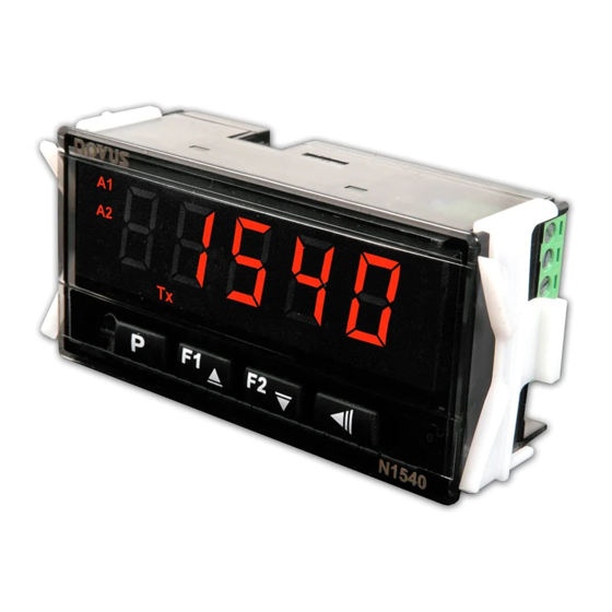
PRESENTATION N1540 is an extremely versatile process controller. It has several types of input, with thermocouples, resistance thermometers and linear voltage and current signals that allow the equipment to indicate the most diverse variables. In addition, it has different alarm functions, display Offset, configuration password protection, serial communication, display in Celsius (°C) or Farenheit (°F) degrees, among other features. -
Page 5: Features
SPA1 Absolute minimum value alarm. Triggers when the PV value is below the point set by ALr-SPA1 (using alarm 1 as an example): difl ALrF – SPA1 ALrF ALrF ALrF – SPA1 positive SPA1 negative SPA1 NOVUS AUTOMATION 5/22... -
Page 6: Alarm Initial Block
The auxiliary supply is another feature available. It is suitable for feeding the process transmitters that generate the input signal for the digital panel meter. Available on terminals 11 and 13 of the rear connector. SERIAL COMMUNICATION For complete information, see APPENDIX 1 – COMUNICATION PROTOCOL. Figure 1 Serial communication NOVUS AUTOMATION 6/22... -
Page 7: Electrical Connections: Rs485 Interface
The digital panel meter allows you to create a connection between display range and output current with inversely proportional behavior (rtll > rtKL). Available on terminals 18 (+) and 19 (-) of the rear connector of the N1540-RT and N1540-RT-24V models. The user can set the retransmission signal between the options 0 to 20 mA and 4 to 20 mA. -
Page 8: Installation / Connections
It is recommended to use RC FILTERS (noise suppressors) in contactor coils, solenoids, etc. • In control applications, it is essential to consider what can happen when any part of the system fails. The internal devices of the equipment do • not guarantee full protection. NOVUS AUTOMATION 8/22... -
Page 9: Operation
Each parameter is shown on the display alternately with its value or condition. According to the protection configuration adopted, the PASS parameter is displayed as the first parameter of the cycle where protection starts. See CONFIGURATION PROTECTION chapter. NOVUS AUTOMATION 9/22... -
Page 10: Parameter Descriptions
Allows you to set the PV retransmission mode: Retr It determines the retransmission in 0-20 mA. Retransmission 0-20 It determines the retransmission in 4-20 mA. 4-20 This parameter will be displayed when PV retransmission is available on the digital panel meter. NOVUS AUTOMATION 10/22... -
Page 11: Custom Linearization Cycle
Allows you to set the frequency of the local power grid. Frequency Sn k Displays the first 4 digits of the serial number. Serial Number High Sn l Displays the last 4 digits of the serial number. Serial Number Low NOVUS AUTOMATION 11/22... -
Page 12: Configuration Protection
6. Read the current value indicated on the milliammeter. Use the keys to adjust the value shown on the digital panel meter. It must match the value shown on the milliammeter. 7. Press the P key to save and access the ovK( parameter. 8. Press NOVUS AUTOMATION 12/22... - Page 13 It must match the value shown on the milliammeter. 10. Read the current indicated on the milliammeter and, using the keys, indicate it in the ovkC parameter. 11. Exit the Calibration Cycle. 12. Validate the calibration performed. NOVUS AUTOMATION 13/22...
-
Page 14: Specifications
AUXILIARY SUPPLY: ................................. 24 Vdc (± 10 %) 20 mA max. HOUSING: ................................IP65, Polycarbonate (PC) UL94 V-2 CONNECTORS: ....................................ABS+PC UL94 V-0 USB INTERFACE: 2.0, CDC class (Virtual serial port), Modbus RTU protocol. STARTUP: 3 seconds after power up. CERTIFICATIONS: 1 F.S.: Full Scale. NOVUS AUTOMATION 14/22... -
Page 15: Identification
IDENTIFICATION MODEL DESCRIPTION N1540 Basic version. N1540-24 Basic version with 24 V power supply. N1540-485 RS485 version. N1540-485-24V RS485 version and 24 power supply. N1540-RT Version with PV Retransmission. N1540-RT-24V Version with PV retransmission and 24 V power supply. Notes: 1. -
Page 16: Maintenance
Open input. No sensor or signal. ---- Connection and/or configuration problems. Err1 Check the connections and configuration. Table 5 Error messages Other error messages displayed by the equipment represent internal damage that necessarily means the device must be sent for maintenance. NOVUS AUTOMATION 16/22... -
Page 17: Warranty
WARRANTY Warranty conditions are available on our website www.novusautomation.com/warranty. NOVUS AUTOMATION 17/22... -
Page 18: Appendix 1 - Comunication Protocol
To use the serial, three parameters must be configured: bavd: Communication speed. All equipment has the same speed. addr: Communication address of the digital panel meter. Each equipment must have a unique address. Prty: Parity. 12.1.5 CONNECTIONS Figure 8 Serial communication NOVUS AUTOMATION 18/22... -
Page 19: Register's Table
Serial Number L Range: 0 to 9999. Read-only. 0014~0016 Reserved. Allows you to set a reference value for the differential alarm. 0017 ALrf Maximum range: From SPLL to the value set in SPkL or the interval of the sensor. NOVUS AUTOMATION 19/22... - Page 20 1 → XX.XX. DP. P O 2 → XXX.X. 3 → XXXX. Reading/Writing: Filter intensity on PV reading. 0053 FLtr Range: 0~20. Reading/Writing: Mains frequency. Range: 0054 Freq 0 → 60 Hz. 1 → 50Hz. 0055 Reserved. NOVUS AUTOMATION 20/22...
- Page 21 0082 0 → Does not restore calibration. Rstr 1 → Restores the calibration. 0083 Reserved. Allows you to set the level of password protection to be used. 0084 Prot Range: 1 to 3. Table 7 Register's table NOVUS AUTOMATION 21/22...
-
Page 22: Status Words
The equipment ignores read commands in Broadcast. Thus, there will be no response. You can only write in Broadcast mode. ERROR CODE ERROR DESCRIPTION Invalid or non-existent command. Invalid or out-of-range register number. Invalid or out-of-range register quantity. Table 10 Error codes in exception response NOVUS AUTOMATION 22/22...
Need help?
Do you have a question about the N1540 and is the answer not in the manual?
Questions and answers