Table of Contents
Advertisement
Quick Links
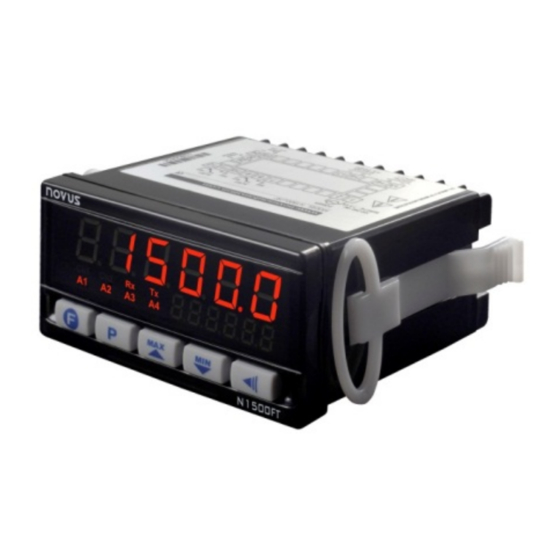
N1500FT Indicator
FLOW RATE INDICATOR – INSTRUCTIONS MANUAL – V1.2x E
SAFETY ALERTS
The symbols below are used on the equipment and throughout this
document to draw the user's attention to important operational and
safety information.
CAUTION:
Read this manual carefully prior to
installation and operation of the
unit.
All safety related instructions that appear in the manual must be
observed to ensure personal safety and to prevent damage to either
the instrument or the system. If the device is used in a manner not
specified in this manual, its safety features may be impaired.
INTRODUCTION
This
flow
rate
indicator
retransmission, alarm and RS485 communication features (optional
RTU Modbus slave). It reads most flow signals available in the
market, such as pulse, magnetic pickup and 4-20 mA. The pulse
input allows connecting sensors with outputs such as reed-switch,
NPN, PNP and tension. Both for pulse input and 4-20 mA input, unit
is selectable and a scale factor is set to turn the input signal into the
unit of choice. It provides an isolated pulse output for totalized flow
retransmission and a 4-20 mA output for immediate flow
retransmission. Alarms are set off through 2 to 4 relays, depending
on the equipment model.
AC models provide a 24 Vdc / 50 mA output.
INPUTS
The flow rate indicator allows for two basic input types:
• Instantaneous flow input through a 4-20 mA signal. In this case,
flow totalization is obtained by integrating instantaneous flow rate.
• Totalized flow input through a pulse signal. In this case,
instantaneous flow rate is obtained by deriving totalized flow rate.
Pulse signals may come from sensors/transmitters with NPN, PNP, dry
contact (reed switch) and tension signal output, or even magnetic
pickup outputs.
When the input is set to 4-20 mA, you should establish on screens
InLL and InKL which flow values are equivalent to 4-20 mA.
When the 4-20 mA input is not used as flow input, it may be used
alternatively as auxiliary input. This way it is possible to measure the
pressure of a pipeline, for instance.
The pulse flow input may be scaled, both for instantaneous and
totalized flow rates (independently), through 'K' multiplication factors:
k.1nst and k.tot.
Both flow time base and unit must be defined on screen Un1t
To do so, there are six characters, the first five of which are used to
set the unit and the last one (to the right) is used to set the time base
on which the flow rate is measured. Available time bases are 's'
(seconds), 'm' (minutes), 'h' (hours) and 'd' (days).
NOVUS AUTOMATION
CAUTION OR DANGER:
Electric shock hazard
provides
indication,
totalization,
With pulse flow input, totalization will continue even if the input rate is
below the minimum rate required. Instantaneous flow rate indication
will be zero whenever there is a time lapse of 10 seconds without
input variation. In this case, whenever there is a totalization increase
(more input pulses), the instantaneous flow value will be shown for
the nest 10 seconds.
"K" FACTORS
The instantaneous K factor (k.1nst) and the total K factor (k.tot)
allow the user to view the instantaneous and totalized flow in different
units.
The instantaneous K factor will be available only in case the selected
flow input type is different from 4-20 mA. When the input type is 4-20
mA, the configured range limits already provide the parameters for
the indication.
Instantaneous flow is directly related to the time base set in
parameter Un1t1.
In case user erroneously configures parameters k.1nSt and k.tot
with value "0" (zero), this will be assigned value "0.00001".
Example 1:
Chosen meter gives us an information of (pulses per volume) 50
pulses per liter. User wants to view the instantaneous flow in liters (l)
and the totalized flow in cubic meters (m³).
In order to do that, parameter k.1nst should be set a value of "50",
so indicating the instantaneous flow in liters. Parameter k.tot should
be set a value of "50000", so indicating the totalized flow in m³.
Instantaneous flow will be viewed based on the selected time base in
Un1t1. In case the example meter output is 50 pulses per second,
which means 1 liter/second, and the selected time base is m
(minute), the instantaneous flow indication will be 60 (liters/minute).
Example 2:
Chosen sensor gives us an information in 4-20 mA that corresponds
to a flow between 0 and 100 liters per minute. User wants to view the
totalized flow in cubic meters (m³).
On this case, parameter 1N.TYPE sholud be selected as 4-20 mA
and parameters InLL and InKL should be configured as "0" and
"100". This way, we pass to the equipment the information that 4 mA
relates to 0 liters per minute and 20 mA relates to 100 liters per
minute. In case sensor output is 12 mA, flow will be displayed as 50
liters/minute.
Parameter k.tot should have a value of 0.001 (1 liter = 0.001 m³).
This way, the totalized flow will be converted and displayed in m³
(cubic meters).
When the instantaneous flow type is selected as 4-20 mA, the time
base selected in Un1t1 have no influence over the indicated values,
having just unit display purposes. The indication conversion from
"liters per minute" to "liters per hour" should be adjusted directly on
input limits InLL and InKL.
In case user wanted instantaneous flow indicated in cubic meters per
hour (m³/h) with the same meter, the values "0" and "6" should have
1.
been selected in input limits InLL and InKL, where the second
value means 100 l/min converted to m³/h. k.tot parameter should
be changed to "1" because input is already in m³.
1/9
Advertisement
Table of Contents

Subscribe to Our Youtube Channel
Related Manuals for Novus N1500FT


Summary of Contents for Novus N1500FT
- Page 1 N1500FT Indicator FLOW RATE INDICATOR – INSTRUCTIONS MANUAL – V1.2x E SAFETY ALERTS With pulse flow input, totalization will continue even if the input rate is below the minimum rate required. Instantaneous flow rate indication The symbols below are used on the equipment and throughout this will be zero whenever there is a time lapse of 10 seconds without document to draw the user’s attention to important operational and...
-
Page 2: Special Functions
N1500FT Flow Indicator CUSTOMIZED LINEARIZATION • Minimum Value – Lo It sets off when the reading is below the value determined by the When the flow rate is read through a 4-20 mA input, it is possible to alarm Setpoint. -
Page 3: Electrical Connections
N1500FT Flow Indicator ELECTRICAL CONNECTIONS AUXILIARY DIGITAL INPUT AND All the inside can be removed without the need to undo the electrical Similarly to a digital input, the key can be set to zero the connections. Disposition of signals in the rear panel of the indicator is totalizer, freeze the main screen, zero minimum and maximum shown in Fig. -
Page 4: Operation
N1500FT Flow Indicator The images below show connections for different output types: Change a digit in the Press while holding value being modified. Available only for some parameters! Press to select the next option or, in the case of a Change a parameter. - Page 5 N1500FT Flow Indicator ALARM CYCLE FUNCTION CYCLE Setup of first screen of the main cycle. See Selection of Alarm 1 function: off, 1.Error, Ma1n Fva1 Table 5. Main screen Prog Lo, x1 and FEEDER. Function Alarm 1 Selection of key function.
- Page 6 N1500FT Flow Indicator For screens that show totalizations, whether it is the total or the SELECTION OF FLOW INPUT TYPE non-resettable value, when the reading cannot be shown in six SENSOR DESCRIPTION digits it will be shown in two halves; that is, the lower six digits and the higher five digits (preceded by a k.
-
Page 7: Configuration Protection
N1500FT Flow Indicator CUSTOMIZED LINEARIZATION CYCLE On this screen, whenever you press ovx( , a standard current close to 20 mA will Output High Lin.enbl Enables linearization. Applicable only when be applied. Measure current, in mA, and enter Calibration Linearization flow input is 4-20 mA. -
Page 8: Serial Communication
N1500FT Flow Indicator Communication signals are electrically isolated from the rest of the MESSAGE PROBLEM DESCRIPTION indicator. Value reading is above limits allowed for this VVVVV • Maximum connection distance: 1000 meters. sensor or signal. • Selectable speed; 8 bits of data; 1 stop bit; selectable parity (no Value reading is below limits allowed for this parity, even or odd). -
Page 9: Specifications
N1500FT Flow Indicator SPECIFICATIONS WARRANTY DIMENSIONS: ..........48 x 96 x 92 mm (1/8 DIN) Warranty conditions available website ............Approximate Weight: 242 g www.novusautomation.com/warranty. PANEL CUTOUT: ........45.5 x 93 mm (+0.5 -0.0 mm) POWER SUPPLY: ..... 100 to 240 Vac/dc (±10 %), 50/60 Hz Optional 24 V: ....
Need help?
Do you have a question about the N1500FT and is the answer not in the manual?
Questions and answers