Table of Contents
Advertisement
Quick Links
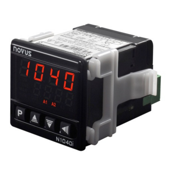
N1040i Digital Panel Meter
UNIVERSAL DIGITAL PANEL METER – USER MANUAL – V2.0x J
SAFETY ALERTS
The symbols below are used on the equipment and throughout this
manual to draw the user´s attention to valuable information related to
the equipment safety and operation.
CAUTION:
Read the manual thoroughly
before installing and operating
the equipment
All safety related instructions that appear in the manual must be
observed to ensure personal safety and to prevent damage to either
the instrument or the system. If the instrument is used in a manner not
specified by the manufacturer, the protection provided by the
equipment may be impaired.
PRESENTATION
N1040i is a versatile digital panel meter. With a wide list of input types
(thermocouples, thermo-resistance, voltage and current), N1040i can
measure most of the variables and sensors encountered in industrial
processes.
Configuration can be performed either directly on the controller or via
the USB interface once QuickTune software has been installed on
the computer to be used. Once connected to USB, the device will be
recognized as a serial communication (COM) port operating with
Modbus RTU protocol.
Through the USB interface, even if disconnected from the power
supply, the configuration performed in a device can be saved in a file
and repeated in other devices that require the same configuration.
It also features various alarm functions, display offset, configuration
with password protection, serial communication, indication in degrees
Celsius (°C) or Fahrenheit (°F), among others.
FEATURES
SIGNAL INPUT (INPUT)
The input type is defined in the device configuration. Table 1
presents the options available:
TYPE
CODE
J
Range: -110 to 950 °C (-166 to 1742 °F)
Tc j
K
Range: -150 to 1370 °C (-238 to 2498 °F)
Tc k
T
Range: -160 to 400 °C (-256 to 752 °F)
Tc t
N
Range: -270 to 1300 °C (-454 to 2372 °F)
Tc n
R
Range: -50 to 1760 °C (-58 to 3200 °F)
Tc r
S
Range: -50 to 1760 °C (-58 to 3200 °F)
Tc s
B
Range: 400 to 1800 °C (752 to 3272 °F)
Tc b
E
Range: -90 to 730 °C (-130 to 1346 °F)
Tc e
Pt100
Range: -200 to 850 °C (-328 to 1562 °F)
Pt
NOVUS AUTOMATION
CAUTION OR DANGER:
Electrical shock hazard
MEASUREMENT RANGE
TYPE
CODE
0-20 mA
L0.20
4-20 mA
L4.20
0–50 mV
Indication programmable from -1999 to
L0.50
0-5 Vdc
L0.5
0-10 Vdc
L0.10
Lnj
Ln k
ln t
4-20 mA
ln n
NON-
ln r
Indication range according to the sensor.
LINEAR
ln s
ln b
ln E
Ln.Pt
Table 1 – Input types
ALARMS
N1040i can have none, one or two alarms. Each alarm present is
associated to one output with the same name (ALARM1 and ALARM2).
OUTPUT ALARM1: Relay SPDT. Available in the following
terminals: 10, 11 and 12.
OUTPUT ALARM2: Relay SPST-NO. Available in the following
terminals: 13 and 14.
These alarms can be configured for the functions described in Table 2:
Alarm off.
off
Alarm of the absolute minimum
value. It triggers when the PV
value is below the value
lo
defined by the alarm Setpoint
(SPA1 or SPA2).
Alarm
of
the
maximum value. It triggers
when the PV value is above
ki
the value defined by the alarm
Setpoint.
Alarm of the differential value. In this function, "SPA1"
and "SPA2" represent errors (difference) between the PV
and the reference value of ALrF.
dif
PV
ALrF–SPA1
ALrF
ALrF+SPA1
SPA1 positive
Alarm of the minimum differential value. It triggers when
the PV value is below the point defined by:
ALrF - SPA1 (using alarm 1 as an example).
difl
PV
ALrF – SPA1
ALrF
SPA1 positive
MEASUREMENT RANGE
Analog Linear Signal
9999.
Non-Linear Analog Signal
SPA1
absolute
PV
SPA1
PV
ALrF + SPA1
ALrF
ALrF – SPA1
SPA1 negative
PV
ALrF
ALrF – SPA1
SPA1 negative
PV
1/7
Advertisement
Table of Contents

Subscribe to Our Youtube Channel
Related Manuals for Novus N1040i


Summary of Contents for Novus N1040i
- Page 1 PRESENTATION N1040i can have none, one or two alarms. Each alarm present is N1040i is a versatile digital panel meter. With a wide list of input types associated to one output with the same name (ALARM1 and ALARM2). (thermocouples, thermo-resistance, voltage and current), N1040i can measure most of the variables and sensors encountered in industrial OUTPUT ALARM1: Relay SPDT.
-
Page 2: Electrical Connections
Allows to correct measurement errors that appear, for example, when replacing the temperature sensor. The 24 Vdc output is on terminals 13 and 14 for models N1040i-RE and N1040i-RE-485. USB INTERFACE The 24 V auxiliary power supply is not electrically isolated from the RS485 serial communication. -
Page 3: Operation
N1040i Digital Panel Meter OPERATION In models with two alarms and serial communication, the connections are: The front panel can be seen in Figure 6: Figure 2 – Alarms and serial communication connections Figure 6 – Identification of the front panel parts... -
Page 4: Calibration Cycle
N1040i Digital Panel Meter PARAMETERS DESCRIPTION Parameter that allows you to make corrections in the 0ffs PV value indicated. Offset OPERATION CYCLE It defines the lower value of the indication range when inll PV display indication. The value of the measured... -
Page 5: Maintenance
N1040i Digital Panel Meter CONFIGURATION PROTECTION INPUT CALIBRATION All input types leave the factory already calibrated. Recalibration is The digital panel meter allows protecting the configuration made by not recommended for inexperienced operators. If it is necessary to the user, preventing undue changes. -
Page 6: Specifications
N1040i Digital Panel Meter SPECIFICATIONS WARRANTY DIMENSIONS: ............48 x 48 x 80 mm Warranty conditions available website www.novusautomation.com/warranty. Approximate weight: ............... 75 g POWER SUPPLY: ..... 100 to 240 Vac/dc (±10 %), 50/60 Hz Optional 24 V ...... 12 a 24 Vdc / 24 Vac (-10 % / +20 %) Maximum consumption: ............ -
Page 7: Appendix 1 − Serial Communication
N1040i Digital Panel Meter APPENDIX 1 − SERIAL COMMUNICATION The digital panel meter may be supplied with an asynchronous serial communication RS-485 interface, with a master-slave connection for communication with a host computer (master). The digital panel meter is always the slave. The communication is always initiated by the master, which sends a command to the slave address with which to communicate.
Need help?
Do you have a question about the N1040i and is the answer not in the manual?
Questions and answers