Table of Contents
Advertisement
Quick Links
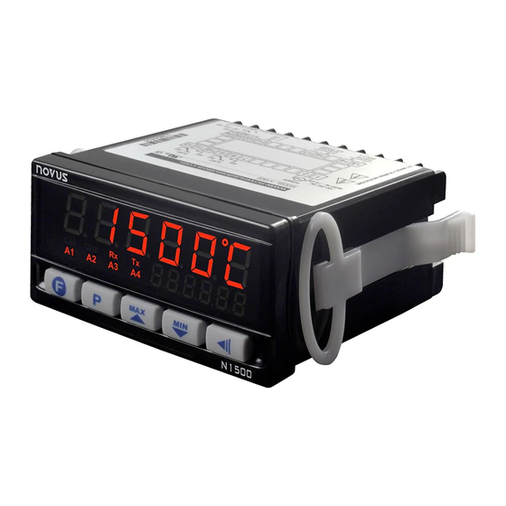
Digital Panel Meter N1500
DIGITAL PANEL METER – USER MANUAL – V2.3x P
SAFETY SUMMARY
The symbols below are used on the equipment and throughout this
document to draw the user's attention to important operational and
safety information.
CAUTION:
Read complete instructions prior
to installation and operation of the
unit.
All safety related instructions that appear in the manual must be
observed to ensure personal safety and to prevent damage to either
the instrument or the system. If the instrument is used in a manner
not specified by the manufacturer, the protection provided by the
equipment may be impaired.
PRESENTATION
N1500 is a digital panel meter which accepts a large variety of input
signals and sensors. A six-digit LED display shows measured value
and all programming parameters.
Instrument configuration is achieved from the keypad, without any
hardware change. Thus, the selection of input type and alarms
modes, besides other special functions, are accessed and defined
from the frontal keypad.
The user should read this manual thoroughly before using the
instrument. It must be handled with care and should be used
accordingly for best results.
Some of the features are:
• Universal input: Pt100, thermocouples, 0-50 mV, 0-5 V, 0-10 V, 0-
20 mA and 4-20 mA.
• Customized indications.
• 24 Vdc power supply for remote transmitter excitation.
• Memory for maximum and minimum values.
• Hold and Peak Hold functions.
• Digital input.
• Increasing or decreasing display.
• Process Variable (PV) retransmission in 0-20 mA or 4-20 mA
(optional).
• RS485 MODBUS RTU serial communication (optional).
• 3rd and 4th alarm relays (optional).
NOVUS AUTOMATION
CAUTION OR WARNING:
Electrical shock hazard.
PROCESS VARIABLE INPUT (PV)
The process variable (PV) input type is configured through the frontal
keypad according to the codes shown in Table 1 (refer to INPUT
TYPE parameter (in. t yp) in
CONFIGURATION
All input types are factory calibrated and no additional calibration is
required. The user does not need to make any adjustments.
TYPE
CODE
Tc j
J
Range: -130 to 940 °C (-202 to 1724 °F)
Tc h
Range: -200 to 1370 °C (-328 to 2498 °F)
K
Tc t
T
Range: -200 to 400 °C (-328 to 752 °F)
Tc e
E
Range: -100 to 720 °C (-148 to 1328 °F)
Tc m
N
Range: -200 to 1300 °C (-328 to 2372 °F)
Tc r
R
Range: 0 to 1760 °C (32 to 3200 °F)
Tc s
S
Range: 0 to 1760 °C (32 to 3200 °F)
Tc b
B
Range: 500 to 1800 °C (932 to 3272 °F)
Pt100
Pt100
Range: -200.0 to 850.0 °C (-328.0 to 1562.0 °F)
0 – 50 mV
0-50
Linear. Programmable indication.
Linear
0 – 5 V
0-5
Linear. Programmable indication.
Linear
0-10 V
0-10
Linear. Programmable indication.
Linear
0 – 50 mV
c. 0 -50
Custom linearization, user configurable.
No Linear
0 – 5 V
c. 0 -5
Custom linearization, user configurable.
No Linear
0-10 V
c. 0 -10
Custom linearization, user configurable.
No Linear
Lin J
T/C type J linearization. Range: -130 to 940 °C
Lin h
T/C type K linearization. Range: -200 to 1370 °C
Lin t
T/C type T linearization. Range: -200 to 400 °C
Lin e
T/C type E linearization. Range: -100 to 720 °C
4-20 mA
Lin m
T/C type N linearization. Range: -200 to 1300 °C
NO
LINEAR
Lin r
T/C type R linearization. Range: 0 to 1760 °C
Lin s
T/C type S linearization. Range: 0 to 1760 °C
Lin b
T/C type B linearization. Range: 500 to 1800 °C
Linpt
Pt100 linearization. Range:-200.0 to 850.0 °C
0-20 mA
0-20A
Linear. Programmable indication.
Linear
4-20 mA
4-20A
Linear. Programmable indication.
Linear
0-20 mA
c. 0 -20
Custom Linearization, user configurable.
No Linear
4-20 mA
c. 4 -20
Custom Linearization, user configurable.
No Linear
Table 1 – Input types
LEVEL).
MEASURING RANGE
1/8
Advertisement
Table of Contents

Subscribe to Our Youtube Channel
Related Manuals for Novus N1500


Summary of Contents for Novus N1500
- Page 1 0 – 50 mV 0-50 Linear. Programmable indication. Linear N1500 is a digital panel meter which accepts a large variety of input signals and sensors. A six-digit LED display shows measured value 0 – 5 V Linear. Programmable indication. and all programming parameters.
- Page 2 N1500 Digital Panel Meter ALARMS TYPE PROMPT ACTION Differential out of The digital panel meter has 2 alarm outputs in the basic version and Dif. o v Positive Deviation range up to 4 alarms outputs optionally. AL SP - Deviation...
-
Page 3: Special Functions
N1500 Digital Panel Meter SPECIAL FUNCTIONS INSTALLATION The digital panel meter is designed to be panel mounted. Remove the MAXIMUM AND MINIMUM two plastic fixing clamps from the instrument, insert the unit into the panel cut-out and slide firmly the fixing clamps from the rear against the The digital panel meter memorizes the measured maximum and panel. -
Page 4: Operation
At the end of each level the display will go back to the work level. The N1500 can deliver either 0-20 mA or 4-20 mA analog output, Note: To access the calibration level, however, it is required to press depending on how the instrument is configured. - Page 5 N1500 Digital Panel Meter CONFIGURATION PROTECTION DiF. H i Differential high As safety measure, parameter changes can be prevented by a DiF. o v Differential outside the range combination of keys, valid for each level. The protected parameters DiF. i n Differential within range.
-
Page 6: Configuration Level
N1500 Digital Panel Meter CONFIGURATION LEVEL Input high limit. Sets the high limit for input type 0- In. k il In. t yp Input type. Selects the input signal or sensor type to 50 mV, 0-5 V, 0-10 V, 0-20 mA or 4-20 mA. -
Page 7: Configurator Software
CONFIGURATOR SOFTWARE SERIAL COMMUNICATION Available for free download from the NOVUS website, QuickTune software is the ideal tool to configure the N1500. It also has The digital panel meter can be supplied with an asynchronous diagnostic tools. RS485 digital communication interface for master-slave connection To configure the device, simply follow the procedure below: to a host computer (master). -
Page 8: Specifications
..... ALM3, ALM4: SPST-NO: 1.5 A / 250 Vac (3 A / 30 Vdc Res.) For full documentation, download the Registers Table for Serial AUXILIARY POWER SUPPLY: ....... 24 Vdc, ±10 %; 25 mA Communication in the N1500 section of our web site: www.novusautomation.com. EMC: ....... EN 61326-1:1997 and EN 61326-1/A1:1998 All registers are 16-bit signed integers.
Need help?
Do you have a question about the N1500 and is the answer not in the manual?
Questions and answers