Sign In
Upload
Download
Table of Contents
Contents
Add to my manuals
Delete from my manuals
Share
URL of this page:
HTML Link:
Bookmark this page
Add
Manual will be automatically added to "My Manuals"
Print this page
×
Bookmark added
×
Added to my manuals
Manuals
Brands
Gree Manuals
Air Conditioner
GWHD(48S)NM3CO
Service manual
Gree GWHD(48S)NM3CO Service Manual
Super free match series
Hide thumbs
Also See for GWHD(48S)NM3CO
:
Service manual
(217 pages)
1
Table Of Contents
2
3
4
5
6
7
8
9
10
11
12
13
14
15
16
17
18
19
20
21
22
23
24
25
26
27
28
29
30
31
32
33
34
35
36
37
38
39
40
41
42
43
44
45
46
47
48
49
50
51
52
53
54
55
56
57
58
59
60
61
62
63
64
65
66
67
68
69
70
71
72
73
74
75
76
77
78
79
80
81
82
83
84
85
86
87
88
89
90
91
92
93
94
95
96
97
98
99
100
101
102
103
104
105
106
107
108
109
110
111
112
113
114
115
116
117
118
119
120
121
122
123
124
125
126
127
128
129
130
131
132
133
134
135
136
137
138
139
140
141
142
143
144
145
146
147
148
149
150
151
152
153
154
155
156
157
158
159
160
161
162
163
164
165
166
167
168
169
170
171
172
173
174
175
176
177
178
179
180
181
182
183
184
185
186
187
188
189
190
191
192
193
194
195
196
197
198
199
200
201
202
203
204
205
206
207
page
of
207
Go
/
207
Contents
Table of Contents
Troubleshooting
Bookmarks
Table of Contents
Table of Contents
Product
Models List
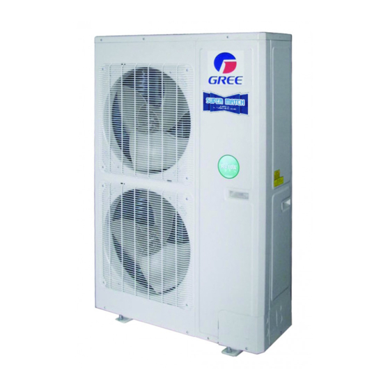
Outdoor Unit
BU Module
Indoor Unit
Nomenclature
Nomenclature of Outdoor Unit
Nomenclature of BU Module
Nomenclature of Indoor Unit
Function
Product Data
Product Data of Outdoor Unit
Product Data of Indoor Unit
Product Data of BU Module
Working Temperature Range
Piping Diagram
Control
Operation Flowchart
Cooling/Dry Operation
Heating Operation
Main Logic
Control Function of Outdoor Unit
Protection Function
Other Function
Control Function of Indoor Unit
Remote Controller
Wired Remote Controller
Wireless Remote Controller YT1F (MOTO)
Function of Press Buttons
Wireless Remote Controller YAA1FB1
Wireless Remote Controller YAG1FB
Wireless Remote Controller YB1F2 (XFAN)
Smart Zone Controller (CE50-24/E)
General Introduction
Communication Network
Lcd
Buttons
Installation
Precautions for Installation
Key Points of Installation
Super Free Match Service Manual
Flow Chart of Installation
Outdoor Unit Installation
Precautions for R410A
Precaution for Installation
Precaution for Operation Test
Names of Main Parts
Parts and Components of Unit
Selection of Installation Location
Outline Dimension of the Outdoor Unit
Installation and Servicing Space
Installation of the Outdoor Unit
Indoor Unit Installation
Installation of Wall Mounted Type
Installation of Duct Type
Installation of Cassette Type
Installation of Floor Ceiling Type
Installation of Console Type
Bu Module Installation
Precaution for Installation
Names of Main Parts
Selection of Installation Location
Outline Dimension and Servicing Space of FXB3A-K
Outline Dimension and Servicing Space of FXB5A-K
Installation Instruction
Refrigeration Piping Work
Allowable Length and Drop Height of Connecting Pipe
Dimension of Connecting Pipe
Connection of Branch Pipe
Design Requirements for Oil Trap
Connection of Outdoor Unit Refrigerant Pipe
Installation of Piping Adapter
Precaution for Connection
Leak Test
Vacuum Operation
Refrigerant Charging
Electrical Wiring Work
Wiring Connection
Requirements of Power Circuit and Cable
Ground Requirements
Precautions of Electrical Wiring Work
Precaution of Laying Wires
Electrical Wiring Work for Outdoor Unit
Electrical Wiring Work for BU Module
Instructions for DIP Switch
Electrical Wiring Work for Indoor Unit
Installation of Drainage Pipeline
Material Quality Requirements for Condensate Pipe
Key Points for Condensate Pipe Installation
Installation of Protective Layer on Connection Pipe
Maintenance
Testing Board Introduction
Compose of Testing Board
Instruction of Function and Data Section
Process Control Setting
Troubleshooting
Check before Contacting Maintenance Serviceman
Problem Handling
Error Description
Flow Chart of Troubleshooting
Malfunction Display: High Pressure Protection
Malfunction Display: Low Pressure Protection
Malfunction Display: Discharge Temperature Protection
Malfunction Display: Current Protection
Malfunction Display: Communication Error
Malfunction Display: Indoor Unit Water Full Protection
Malfunction Display: Temperature Sensor Error
Malfunction Display: High/Low Pressure Sensor Error
Power Distribution
Diagram of Power Distribution
Wiring Diagram
The Resistances of Common Temperature Sensors
15 Kω
20 Kω
50 Kω
Disassembly and Assembly Procedure of Main Parts
Outdoor Unit
Indoor Unit
Removal and Assembly of Fan Motor
Separate the Motor
Remove the
Remove the Fan
Unscrew the Fixed Screws of the Water Tray
Remove the Water Tray
Operation Instructions
Exploded Views and Part List
Outdoor Unit
Indoor Unit
BU Module
Advertisement
Quick Links
1
Models List
2
Indoor Unit
3
Outdoor Unit
Download this manual
CENTRAL AIR CONDITIONERS
SUPER FREE MATCH SERIES
SERVICE MANUAL
T1/R410A/50Hz
( GC201405 - )
Table of
Contents
Previous
Page
Next
Page
1
2
3
4
5
Advertisement
Table of Contents
Troubleshooting
Troubleshooting
127
FLOW CHART OF TROUBLESHOOTING
131
Need help?
Do you have a question about the GWHD(48S)NM3CO and is the answer not in the manual?
Ask a question
Questions and answers
Related Manuals for Gree GWHD(48S)NM3CO
Air Conditioner Gree R410A Service Manual
Super free match series t1/r410a/50hz (217 pages)
Air Conditioner Gree GC201306 -1 Service Manual
Super free match series, t1/r410a/50hz (216 pages)
Air Conditioner Gree GFH(09)EA-K3DNA1A/I Service Manual
(86 pages)
Air Conditioner Gree GWH(09)KF-K3DNA6E/I Service Manual
(60 pages)
Air Conditioner Gree GWH(09)RA-K3DNA1E/I Service Manual
(58 pages)
Air Conditioner Gree R410A Service Manual
Free match ii multi vrf (42 pages)
Air Conditioner Gree GWH09MA-K3DNA2B Service Manual
(38 pages)
Air Conditioner Gree gwhd(18)nk3fo Service Manual
Refrigerant: r410a (112 pages)
Air Conditioner Gree GWHD(18)NK3FO Service Manual
Gree gwhd(18)nk3fo; gwhd(24)nk3fo; gwhd(24)nk3go; gwhd(28)nk3fo; gwhd(36)nk3bo; gwhd(42)nk3ao air conditioners (112 pages)
Air Conditioner Gree GWHD14NK3BO Service Manual
(108 pages)
Air Conditioner Gree GWHD24NK3FO Service Manual
(114 pages)
Air Conditioner Gree GWHD(14)NK6LO Owner's Manual
Split air conditioner (66 pages)
Air Conditioner Gree SUPER+MULTI ULTRA Series Installation & Owner's Manual
R410a systems-outdoor unit (36 pages)
Air Conditioner Gree GWHD(14)NK6OO(LC)(LH) Service Manual
(111 pages)
Air Conditioner Gree GWHD(48S)NM3DO Owner's Manual
(98 pages)
Air Conditioner Gree SUPER+ MULTI ULTRA Series Service Manual
(196 pages)
This manual is also suitable for:
Gwh(09)ta-k3dna1e/i
Gwhd(56s)nm3co
Gwh(12)tb-k3dna1e/i
Fxb5a-k
Gwh(18)tc-k3dna1e/i
Gwh(28)td-k3dna1c/i
...
Show all
Gwh(07)ua-k3dna1b/i
Gwh(09)ua-k3dna1b/i
Gwh(12)ub-k3dna1b/i
Gwh(18)uc-k3dna1b/i
Gwh(07)ta-k3dna1e/i
Gwh(07)ma-k3dna3e/i
Gwh(09)ma-k3dna3e/i
Gwh(12)mb-k3dna3e/i
Gwh(18)mc-k3dna3e/i
Gwh(07)kf-k3dna6e/i
Gwh(09)kf-k3dna6e/i
Fxb3a-k
Gwh(12)kf-k3dna6e/i
Gwh(18)kg-k3dna6e/i
Gwh(07)ra-k3dna3e/i
Gwh(09)ra-k3dna3e/i
Gwh(12)rb-k3dna3e/i
Gwh(18)rc-k3dna3e/i
Gwh(24)rc-k3dna1a/i
Gfh(09)ea-k3dna1a/i
Gfh(12)ea-k3dna1a/i
Gfh(18)ea-k3dna1a/i
Gfh(21)ea-k3dna1a/i
Gfh(24)ea-k3dna1a/i
Gkh(12)ba-k3dna2a/i
Gkh(18)ba-k3dna2a/i
Gkh(12)ba-k3dna1a/i
Gkh(18)ba-k3dna1a/i
Gkh(24)ba-k3dna1a/i
Gth(09)ba-k3dna1a/i
Gth(12)ba-k3dna1a/i
Gth(18)ba-k3dna1a/i
Gth(24)ba-k3dna1a/i
Geh(09)aa-k3dna1c/i
Geh(12)aa-k3dna1c/i
Geh(18)aa-k3dna1c/i
Table of Contents
Print
Rename the bookmark
Delete bookmark?
Delete from my manuals?
Login
Sign In
OR
Sign in with Facebook
Sign in with Google
Upload manual
Upload from disk
Upload from URL


Need help?
Do you have a question about the GWHD(48S)NM3CO and is the answer not in the manual?
Questions and answers